I've been off-and-on working on a C3M-300B two-chassis amplifier for a while. Everything is completed except some of the final grounding in the signal chassis. I wanted to ask the forum for advice on these last few ground connections before drilling any new holes in an otherwise finished chassis. Here's the info:
The two chassis are connected by a 10-conductor umbilical. I have 2 free signal grounds and one dedicated chassis ground running through the umbilical. The chassis ground wire also connects the umbilical copper shield at the PSU end. The L+R channels are outlined in the schematic diagram below. How would you best connect the left and right ground busses as well as speaker grounds with the available connections?
Thanks for your input. Picture are below.
Hello,
nice work, i would make a starpoint inside the amp and use 2 wires in parallel to have a strong connection to the power supply. this is a vital question when splitting power and amp in two housings. i did this design principle several times but hat the last smooting cap in the amp, you could do the same and think of the long wire as a small resistor, your way of stargrounding is best done with powersupply or atleast hte regulator inside the same chassis
greetings
klaus
If I understand your suggestion correctly VTR, in the signal chassis you would star ground all of the ground busses, speaker grounds, and last smoothing caps (80uF) to one point, then use the two available grounds in the umbilical in parallel to carry this common star ground back to the PSU star ground?
My original thought (and please correct me if this sounds like a bad idea) was this:
jumper the ground busses from each channel together (e.g., ground bus L2 to ground bus L1 connected at the bottom of the 22uF bypass caps), then star ground the now common LEFT and RIGHT busses together from their input sides WITH the 80uF smoothing caps, and connect to one available ground in the umbilical. The speaker grounds would then be star grounded together and carried via the second available ground in the umbilical back to the PSU star ground.
OR what if I star grounded the 80uF smoothing caps together with the speaker grounds and brought that back on one ground conductor. The other conductor would carry the star grounded LEFT and RIGHT ground busses.
Last edited:
I used some beefy 19 pin Amphenol connectors for a 2a3 PP build last year. With 10 pins it might be tight but it looks like you can make it work.
When I did this last, I used a separate B+ for each channel, and a separate ground as well. Chassis was grounded through the shield. I used good quality Amphenol connectors with really solid shield. No extra ground for the chassis - no ground loops, no hum...
Be careful as to never have live pins exposed. Nice work!")
Ian
When I did this last, I used a separate B+ for each channel, and a separate ground as well. Chassis was grounded through the shield. I used good quality Amphenol connectors with really solid shield. No extra ground for the chassis - no ground loops, no hum...
Be careful as to never have live pins exposed. Nice work!
Ian
Last edited:
Soulmerchant: All heaters are DC using Peter Millet's filament circuit. My Amphenol connector is 10 pin and all pins are currently occupied. The three grounds I have available are the two for circuit and one for chassis ground.
My main concern is bringing the final smoothing cap (80uF) and speaker ground together with the low-signal input side before sending it through the umbilical. I think I'll test it out with jumpers and see what works best. I was just hoping someone had a solid recommendation before I committed.
My main concern is bringing the final smoothing cap (80uF) and speaker ground together with the low-signal input side before sending it through the umbilical. I think I'll test it out with jumpers and see what works best. I was just hoping someone had a solid recommendation before I committed.
By all means try it in the PS chassis if you already have the hole drilled.
If you get hum, try it in the amplification chassis instead - just strap it under the chassis, etc. If you are stressed for space in the amplification chassis try a DC Link cap instead...
If you get hum, try it in the amplification chassis instead - just strap it under the chassis, etc. If you are stressed for space in the amplification chassis try a DC Link cap instead...
Last edited:

grounding
hi,
your last idea seems fine to me, i would
not ground the output transformer (i know a safety issue) but it sounds better in my systems
add a additional 50uf smooting cap in the amp or move the last cap from the ps to the amp
keep the stargrounding in the amp (so extra greund return for the c3m stage)
and then test
and can you tell me about the driver stage, did you test it or its recommended from someone else
greetings
klaus
Soulmerchant: The 80uF smoothing caps are already in the amplifier chassis. How about the following arrangement:
IMHO this is the most worse case.
80uF is part of the first stage, so I already grounding it to the stage's virtual grounding point (cathode resistor ground leg).
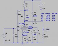
Your C3M operating point is a bit "hot", near to the 4W limit, thus distortion at high levels is over 4-5%!
My op. point is enough safe (3.5W), and THD is acceptable.
BTW I hate tetrode operation of high Gm tubes (D3a, C3g, C3m etc. -I prefer trioded tubes-). Even at moderated output level the 3th /odd/ harmonics is equal, or greater than 2nd, therefore the sound is "sonorous".
Attachments
can you tell me about the driver stage, did you test it or its recommended from someone else
VTR: No testing—operating points were based on comments and other schematics where they were putting around 225V on the C3M plates (example 1, example 2). Also, in Thorsten Loesch's Legacy Amplifier, he commented that when changing to the C3M "the anode Voltage is nominally 225V."
Could you explain the principle behind this idea? Is it for the sake of grounding, ripple reduction, or something inherent to using the umbilical?add a additional 50uf smooting cap in the amp or move the last cap from the ps to the amp
Euro21: Thanks for the schematic and virtual testing. Along with VTR's concern, now I'm not so sure about the operating point. Otherwise, you would recommend grounding the 80uF smoothing caps to their respective C3M cathode, then making a star ground for the driver stages and take that to the umbilical?
Only considering the grounding pattern, is this roughly what you're talking about euro21:

This is my creed:
- Use local start ground for EACH stage;
- Connect this stage all part's ground leg to this local star ground;
- Use insulated input connector, connect "cold" wire to the first stage local star ground;
- Each channel is independent! Don't share ground wire!
- Connect local start grounds of channel to channel's star ground;
- Connect EACH channel ground and B+ wire -screwed up- independently to the PSU (direct, or via umbilical); Don't share power wires between channels!
- The PSU's most noisy point is the first capacitor -after the rectifier-. Don't use this for ground point!
- The channels common ground point is the PSU's last capacitor "ground" leg;
- Be careful when connecting -via umbilical- PSU's metal case and amplifier box case. Sometimes this is the source of hum. Try to use switch within the amplifier box. Sometimes the better solution is connecting one channel's star ground to metal chassis.
I've temporarily hooked up all the grounds and begun testing voltages. Thankfully no explosions on the inaugural power up. With only the rectifiers plugged in I'm getting 420VDC as my main B+ (target 430 but I'll take it). Oddly, however, I'm getting almost the same on the C3M anode. Resistance between the main B+ and C3M anode is a little under 13K, as it should be. Thinking this was a loading vs. unloading issue I tried plugging in the C3M but quickly pulled the plug when the anode peaked over 360VDC (didn't wait to see how high it would go). Same thing happened regardless if the input was shorted to ground or not.
Admittedly, I don't have as much experience under my belt as some of the other diyAudio members, but anyone have any thoughts?
Only other voltages I tested were the C3M screen grid (155VDC) and 300B anode (unloaded, 414VDC). All the filament voltages are exactly where they should be.
Admittedly, I don't have as much experience under my belt as some of the other diyAudio members, but anyone have any thoughts?
Only other voltages I tested were the C3M screen grid (155VDC) and 300B anode (unloaded, 414VDC). All the filament voltages are exactly where they should be.
IMHO this is the most worse case.
Kind of opinion, but ok. My builds don't hum and I assume yours don't either.
This whole talk of different star ground points in general disagrees with me to be honest and the whole talk about where the "star ground point" should be sounds a bit ridiculous.
I would just use a single ground bus in the power supply and be done with it. I really doubt it matters in which chassis the 80uF cap goes, but he already drilled holes for it in the "amplification" chassis. In this case he can simply try it out and see if it is OK or not.
I would not advise him to re-drill his chassis without simply trying it out first.
BTW I hate tetrode operation of high Gm tubes (D3a, C3g, C3m etc. -I prefer trioded tubes-). Even at moderated output level the 3th /odd/ harmonics is equal, or greater than 2nd, therefore the sound is "sonorous".
From my experience, C3M is a stellar performer in pentode, but triode strapped with cascoded CCS has at best an amplification factor of only 18. So is your advise to use triode strapped D3a instead? I have used both and see no problem in using C3M in pentode - many others have used it in the past this way too.
If we start the distortion argument, we will have to scrap single-ended topology for PP, and bring in some judiciously applied global feedback. Please don't push the thread down that route!
Your point about the hot operating point is quite valid - I missed that. Thanks!
Last edited:
I've temporarily hooked up all the grounds and begun testing voltages. Thankfully no explosions on the inaugural power up. With only the rectifiers plugged in I'm getting 420VDC as my main B+ (target 430 but I'll take it). Oddly, however, I'm getting almost the same on the C3M anode. Resistance between the main B+ and C3M anode is a little under 13K, as it should be. Thinking this was a loading vs. unloading issue I tried plugging in the C3M but quickly pulled the plug when the anode peaked over 360VDC (didn't wait to see how high it would go). Same thing happened regardless if the input was shorted to ground or not.
Admittedly, I don't have as much experience under my belt as some of the other diyAudio members, but anyone have any thoughts?
Only other voltages I tested were the C3M screen grid (155VDC) and 300B anode (unloaded, 414VDC). All the filament voltages are exactly where they should be.
Re-check your circuit. Do you have a variac? I find this piece of equipment extremely useful for bringing up a new build nice and slow while measuring different points.
Its quite simple measure the cathode voltage and calculate the current. If you are running 16mA then you should measure 4 volts on the C3M cathode. If you are getting 430 volts on the anode, then you're not passing any current... for example, the cathode resistor might not be connected to ,earth..... so check all your grounds thoroughly.
Ian
Last edited:
Ian (soulmerchant), and anyone else watching:
Back into testing today, trying to figure out what's happening with my voltages. Here are some measurements I've taken at various points under different conditions:

Not sure why the B+ is dipping by ~36% under load. I've checked and rechecked my wiring and I can't find any errors. Plugged into a speaker the amp is dead quiet, and hums as expected when shorting the input with my finger. My PT is stepped and currently wired for 575 output; I can go up to 625 if need be.
Thoughts?
Back into testing today, trying to figure out what's happening with my voltages. Here are some measurements I've taken at various points under different conditions:
Not sure why the B+ is dipping by ~36% under load. I've checked and rechecked my wiring and I can't find any errors. Plugged into a speaker the amp is dead quiet, and hums as expected when shorting the input with my finger. My PT is stepped and currently wired for 575 output; I can go up to 625 if need be.
Thoughts?
Hi
When I use Duncan Amps PSU Designer II to quickly simulate your power supply with no load (= no tubes), The B+ at C2 should be around 500V.
I made a fairly rough assumption that the Power transformer secondary resistance was around 180 ohms and choke DCR of around 100 ohms each. More detail would help. It pays to simulate your PSU before building it. Duncan Amps PSU II is free and not terribly difficult to use. Also, it pays to breadboard your build first... but you probably realized this now.
Your unloaded B+ should be higher. I accounted for your screen divider, which adds up to only 32k ohms (20k + 12k). I hope these resistors are rated high enough. I would bias differently, but that is another story perhaps.
In any case, you have a screen divider on each channel, so they are in parallel - with two 91k Oh bleeders in the PSU. These restive loads in parallel create something like 10k resistive load in total.. When I simulate this, I get an unloaded B+ of ~500V, and if I insert a 150mA current tap, the B+ drops to around 415V.
Hmmmmmm...... I see on your sheet that you reference the 6ax4 heaters to ground. I would definitely not do that - I would float them. You do need to reference the heaters of the C3G to ground - for example, using a 2 watt 100 Ohm wire wound resistor on each secondary to ground.
Otherwise, it seems clear to me that the problem (leak) is in the power supply.
Ian
Last edited:
- Home
- Amplifiers
- Tubes / Valves
- Finishing a C3M-300B