btw - I think you will find that driving 300b as in your schematic will not be that easy... The 300b needs really low impedance source.
You could try a MOSFET source follower - once you get the PSU sorted. 😉
Ian
PS- I hope the 250 Ohm cathode resistor on the C3M is somehow non-inductive. If its a standard 2 watt wire-wound (inductive) resistor then the sound is usually meh...
You could try a MOSFET source follower - once you get the PSU sorted. 😉
Ian
PS- I hope the 250 Ohm cathode resistor on the C3M is somehow non-inductive. If its a standard 2 watt wire-wound (inductive) resistor then the sound is usually meh...
Last edited:
Not sure why the B+ is dipping by ~36% under load.
IMHO your HT transformer is undersized.
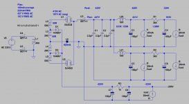
Some years ago I build (actually rebuild, only chassis and 300B tubes remained) trioded C3g -gyrator loaded-, source follower, 300B SE amp to my friend.
This is the PSU.
The static power requirement is about 128VA, so the custom wound power transformer must capable about 250VA.
Attachments
Hi Euro21
His B+ Dips far too much already, without valves inserted. It would really have to be phenominally underrated to deliver such results....
I think he needs to float the damper diode heaters.
Also, for full wave damper diode rectification, if I had two heater windings available, I would put the upper dampers on one winding, and the lower dampers on the other winding. Float each winding.
Not sure if this will make a difference though...
Did he mention detailed specs on his components already?
Ian
Last edited:
Figured out the problem: on one of the 6AX4s I had accidentally soldered to pin 2 (internal connection) instead of pin 3 (cathode). Now my voltages are in the range of expected but need some tweaking.
300B Plate: 447 VDC
300B Cathode: 72.1 VDC
C3M Plate: 255 VDC
C3M Screen: 151 VDC
C3M Cathode: 4.6 VDC
You actually helped me with some of that when I was first planning this build in early 2016. Here is some info on my PT: Thomas Mayer custom, stepped primary (115, 120, 125V), 400mA stepped secondary (100V to 625V in 25V increments); primary DCR 32.7R (on 125V primary), secondary DCR 12.3 (on 575V secondary).
All my resistors are non-inductive. The 1K resistors leading to each channel are Vishay 25W. The 12Ks and 20Ks are 12W Mills.
How do you feel about the 300B plate? 447V is definitely close to the 450V limit. With 72V on the cathode this puts me around 83mA. I definitely need to drop the C3M plate. If I keep the high voltage on the 300B I could increase the C3M plate resistor to 22k, which should put me around 220V.
300B Plate: 447 VDC
300B Cathode: 72.1 VDC
C3M Plate: 255 VDC
C3M Screen: 151 VDC
C3M Cathode: 4.6 VDC
Soulmerchant: It pays to simulate your PSU before building it. Duncan Amps PSU II is free and not terribly difficult to use.
You actually helped me with some of that when I was first planning this build in early 2016. Here is some info on my PT: Thomas Mayer custom, stepped primary (115, 120, 125V), 400mA stepped secondary (100V to 625V in 25V increments); primary DCR 32.7R (on 125V primary), secondary DCR 12.3 (on 575V secondary).
All my resistors are non-inductive. The 1K resistors leading to each channel are Vishay 25W. The 12Ks and 20Ks are 12W Mills.
How do you feel about the 300B plate? 447V is definitely close to the 450V limit. With 72V on the cathode this puts me around 83mA. I definitely need to drop the C3M plate. If I keep the high voltage on the 300B I could increase the C3M plate resistor to 22k, which should put me around 220V.
Another option would be to step the secondary tap down from 575 to 550. On my original PSUII simulation with all the transformer info plugged in (578V, 12.3R) I got 439V for the B+ at C2. This is approximately 1% lower from my measured value of 447V. Dropping the secondary to 553V (578-25=553) in PSUII with 12.3R source resistance, I get 416V at C2. Factoring the 1% increase, that brings me almost exactly to 420V at C2. Furthermore, if I'm doing my math right, with the existing 13K total resistance between C2 and the C3M plate (assuming 16mA current draw for the C3M), I should get about 211V on the C3M plate.
How about that?
How about that?
Last edited:
OK. SCRATCH MOST OF WHAT I SAID ABOVE.
I posted prematurely. In my excitement of fixing the rectifier problem I didn't realize I was still testing under half load: only one channel had tubes installed. Now, with tubes in BOTH channels, I get the following measurements:
300B plates: 419V
300B cathodes: 67V
300B current draw (calculated): 77mA
C3M plates: 249V
C3M screens:141V
C3M cathodes: 4.2V
C3M current draw (calculated): 16mA
Obviously I need to bring C3M plate voltage down and screen voltage up. I'm OK with the 300B where it is.
I could bring the C3M plate to 225 by increasing the plate resistor to 13.8K (calculated).
Not sure why my screen voltage is low—doing the math I should be getting 157V with 419V input, R1 at 20K and R2 at 12k. Should I incrementally increase R2 until I get a satisfactory value?
Thomas Mayer's power transformers are exceptionally good quality (shameless plug, but its true). I use them myself. 🙂
Glad you figured out the source of the drop. I would definitely try the 550V secondaries if needed. Please comment on the sound too 😀
Ian
Glad you figured out the source of the drop. I would definitely try the 550V secondaries if needed. Please comment on the sound too 😀
Ian
Ok, here's an suggestion: I like to use a zener on the screen.
Otherwise I might try a voltage divider of 270k over 150k.
420V *(150k/(270k+150k)= 150V
Bypassed by a suitable cap of course. Then I would use 220V on the plate running 17mA like in the Telefunken specs sheet.
Ian
Otherwise I might try a voltage divider of 270k over 150k.
420V *(150k/(270k+150k)= 150V
Bypassed by a suitable cap of course. Then I would use 220V on the plate running 17mA like in the Telefunken specs sheet.
Ian
Last edited:
Congrats for finding the culprit....I had 300B mono amps for several years and experimented quite a bit with them. Tried driver tubes from 6SL7 SRPP/Mu/parallel/CCS; also pentodes like E180f, E810f, D3a in Triode and pentode, E81L in both modes, and finally C3g and then at last C3o, which was by far the best for my taste. Similar OP than yours, except running the 300B at a little lower current of around 60mA and fixing the screen with a Zener to the cathode to nail the voltage at 150V stable.
I added a small preamp choke and a 10µF film cap from B+ to the driver HV to decrease voltage a little and decouple and further smoothing.
I recently built a small EL84 SEP amp and used these VB408 replacement PCBs for the screen with very good results:hochvolt Labornetzgerät regelbar Platine VB408 Class A verstärker Röhrenradio | eBay Rock stable and sounded significantly better than simple resistor/cap decoupling.
Sound was really good with this C3o, effortless and smoother than all others. Probably the K3/5/7 from both driver and powertube were cancelling out, so that mainly even order harmonics remained. But thats just a theory, not measured as I cannot do that.
Do you have some pics from the inside?😛
Edit:added a amateurish schematic of my former driver satge
Attachments
Last edited:
Don't remember the screen current (4-5mA).
Of course - that must be it. 😉
As I have mentioned, zeners are a good option at setting screen volts. For 150V, the BZW03C150 might be a nice part to consider.
Ian
Of course - that must be it. 😉
As I have mentioned, zeners are a good option at setting screen volts. For 150V, the BZW03C150 might be a nice part to consider.
Ian
All my usual part suppliers (Digikey, Mouser, etc.) don't have the BZW03C150 in stock. I might eventually move to the Zener, but in the meantime I'll probably stick with a simple voltage divider until I get everything hammered down.
I hooked a few high-wattage pots up in series with the 1K channel dividing resistor and the 12K on the bottom leg of the screen voltage divider. I found that keeping the channel divider at 1K and increasing the bottom leg of the screen divider to 13.8K puts me at exactly 151V on the screen and 220V on the C3M plate. Unless anyone sees anything catastrophically wrong with that I'll replace the 12K resistor with two 27K resistors in parallel (13.5K).
Here are a couple internal pics:
PSU

Amplifier:

Don't mind the jumpers off the 40uF caps in parallel—they're there until I decide exactly where I want to ground them. Right now only the right channel (screen left) is hooked up to a speaker; the left (screen right) is hooked up to a dummy load.
Last edited by a moderator:
Very tidy build! I see that there are also 5W zeners at mouser and digitec that would be ok too. But for now, adjusting the divider to get the correct screen voltage will be fine too.
Did you do any listening? I really think using a source follower will make a big difference - the output impedance of the c3m in your circuit is much too high for 300b.
R = ra || Rp
R = 250k || 12k
R = 11.45k
You really want to get output impedance well below 1k for 300b. IRFBC20 running as a source follower with at least 10mA is what I would do. This will of course drop your B+ some.
Ian
Do you have only one heater for all (four) rectifiers?
I was thinking the same thing earlier. According to the RCA 6ax4 specs sheet, peak heater-cathode voltage is 300V for Heater positive wrt cathode, with the DC component not exceeding 100V.
If you look at some of Thomas Mayer's schematics, he uses a separate heater winding for the 'upper' dampers and 'lower' dampers. The 6.3V secondaries on his transformers (at least the ones I use) are rated for 5A.
In my builds, I do full wave with damper diodes and a graetz bridge using two 1n4007's and let the 'upper' damper heaters float.
Ian
Do you have only one heater for all (four) rectifiers?
Currently I do. The transformer comes with two 6.3V, 7.5A taps (only using one for all four 6AX4 right now). I see what you're saying about peak heater-cathode voltage. I'll change the upper and lower dampers to be on their own taps.
As for the zener, how about this ON Semiconductor 150V 5W? I would rather use a Vishay for brand familiarity, but none of their items at a sufficient wattage are actively available that I can find.
The only "listening" I've done is through one speaker hooked up during testing to make sure nothing was oscillating out of control. If I were to go with a MOSFET source-follower such as the IRFBC20, do you have any example schematics I could use as reference? I'm currently at work and can't do too much perusing. I'm a little trepidatious about putting semiconductors in my amp, but I understand what you're saying about the source impedance. Could you describe in words any sonic difference, if any, one can expect by better matching the impedance?
Hi!
No, I don't.
In power supplies with DC output voltages up to about 600V all heaters can share the same winding which should be referenced to ground. TV dampers typically have a 900V DC rating for the cathode positive to the heater. They have a much lower rating for the cathode negative to the heater. But if connected as described the limits are maintained.
For higher voltages it won't help to separate the heaters of upper and lower diodes only. The diodes with their cathodes at AC will have AC voltage of opposite phase. In this case 3 separate heater windings are needed. A common one for the two upper diodes and two separate windings for the lower diodes. I do that in supplies for 211 amps.
Both heater windings can be used however to supply two pairs of diodes separately to reduce the current in the wiring. In the case of voltages we are talking about here both can be referenced to ground
Best regards
Thomas
If you look at some of Thomas Mayer's schematics, he uses a separate heater winding for the 'upper' dampers and 'lower' dampers. The 6.3V secondaries on his transformers (at least the ones I use) are rated for 5A.
No, I don't.
In power supplies with DC output voltages up to about 600V all heaters can share the same winding which should be referenced to ground. TV dampers typically have a 900V DC rating for the cathode positive to the heater. They have a much lower rating for the cathode negative to the heater. But if connected as described the limits are maintained.
For higher voltages it won't help to separate the heaters of upper and lower diodes only. The diodes with their cathodes at AC will have AC voltage of opposite phase. In this case 3 separate heater windings are needed. A common one for the two upper diodes and two separate windings for the lower diodes. I do that in supplies for 211 amps.
Both heater windings can be used however to supply two pairs of diodes separately to reduce the current in the wiring. In the case of voltages we are talking about here both can be referenced to ground
Best regards
Thomas
Many thanks for clarification Thomas!
I think your blog entry is here for this:
http://vinylsavor.blogspot.ch/2011/03/tube-of-month-6ax4.html
Best regards
Ian
I think your blog entry is here for this:
http://vinylsavor.blogspot.ch/2011/03/tube-of-month-6ax4.html
Best regards
Ian
Last edited:
- Home
- Amplifiers
- Tubes / Valves
- Finishing a C3M-300B