Hi Ian,
yes and that post states exactly what I wrote above. The schematic shows three separate heater windings.
Thomas
yes and that post states exactly what I wrote above. The schematic shows three separate heater windings.
Thomas
Currently I do. The transformer comes with two 6.3V, 7.5A taps (only using one for all four 6AX4 right now). I see what you're saying about peak heater-cathode voltage. I'll change the upper and lower dampers to be on their own taps
Ok so this is clearly not necessary after Thomas' very sound advice. 🙂
As for the zener, how about this ON Semiconductor 150V 5W? I would rather use a Vishay for brand familiarity, but none of their items at a sufficient wattage are actively available that I can find.
I'd have no problem using that part.
The only "listening" I've done is through one speaker hooked up during testing to make sure nothing was oscillating out of control. If I were to go with a MOSFET source-follower such as the IRFBC20, do you have any example schematics I could use as reference?
Ok, so first of all I hope the other channel is also connected to a speaker. I personally don't like to run tube/valve amps without a load on the OPT secondary. Its just one of those things... 🙂
Check out R.G. Keen's Mosfet follies here:
http://www.geofex.com/Article_Folders/mosfet_folly/mosfetfolly.htm
Your C3M plate is at around 220V, so if you direct couple it to the gate of the IRFBC20 you could use something around 18-20k resistor drain to ground to get 11-12mA. This resistor will need to dissipate a few watts, and from my experience, it also helps if this resistor is not inductive...
Then you simply Cap couple the drain to the grid of the 300b just like in your schematic. A heatsink on the MOSFET is a good idea since it will need to dissipate a couple of Watts.
The MOSFET will obviously will drop your B+ some more, but I think it will be quite alright for testing purposes.
I'm currently at work and can't do too much perusing. I'm a little trepidatious about putting semiconductors in my amp, but I understand what you're saying about the source impedance. Could you describe in words any sonic difference, if any, one can expect by better matching the impedance?
I would suggest this: Build your 300b like in your schematic, then build a small test board with the heatsinked MOSFET on it for 'testing' purposes. I would be surprised if you did not hear a significant improvement in fidelity.
Ian
Last edited:
If I were to go with a MOSFET source-follower such as the IRFBC20, do you have any example schematics I could use as reference?
As I wrote in the #22 post:
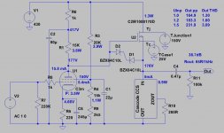
"Some years ago I build (actually rebuild, only chassis and 300B tubes remained) trioded C3g -gyrator loaded-, source follower, 300B SE amp to my friend."
I actually used 2SK2700 as source follower. Other high voltage FETs (with low Crss) -for example 2SK3564..66, AOT1N60, C2..C3 type SiC MOSFETs- also usable.
Attachments
Hi ddroukas
In my post #42 above I see a mistake that is quite obvious - you should of course cap couple the MOSFET source to the grid of the 300b...It's morning here and I still needed coffee. 😉
euro21's schematic looks interesting!
In my post #42 above I see a mistake that is quite obvious - you should of course cap couple the MOSFET source to the grid of the 300b...It's morning here and I still needed coffee. 😉
euro21's schematic looks interesting!
Also, from your earlier posts, I get the impression that your c3m comes up rather slowly. If this is the case, then you might need to use something to protect the MOSFET gate.
Euro21's solution is to cap couple the anode of the input/driver tube to the MOSFET and use a separate bias circuit. This allows to gate to be isolated and should protect it.
Ian
Euro21's solution is to cap couple the anode of the input/driver tube to the MOSFET and use a separate bias circuit. This allows to gate to be isolated and should protect it.
Ian
then you might need to use something to protect the MOSFET gate.
In this case (VAS direct coupled to CF) opposite protecting zeners are always required. I also use CCS as CF load to limiting FET current.
Attachments
This last post is very similar to something I have done before. I was too nervous to use 250mW zeners though, and had some bigger ones on hand anyway.
Ian
Ian
Hey folks,
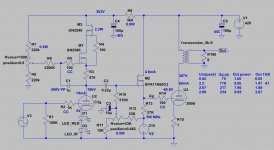
I am bulding the Thorsten Loesch amp and I have a few questions:
- wrt the c3m g2 voltage divider what is the proper voltage I should end up with? I am looking at the original TL schematic that uses 20k and 12k and set g2 at 160v but then looking at the glass audio circuit (F Cappelleti)I find 47k and 68k that would put the g2 voltage at a higher value and flow a lot less current. What's the logic here? Also, how much current should flow in the divider?
-AC or DC for the c3m filament? I have seen both.
-I noticed a couple of small differences around the positioning of the caps around the 300b filament the caps on f+ instead of in parallel to the bias resistor AND a new 15uF cap in the circuit of the first post in this thread. What is the idea for these changes?
- what is the optimal and safe bias current for a 300B. I see people tweak the bias from 890 down to 824 ohms. I have 3.5K primary OPTs.
-finally: the ground break circuit what are the components used there?
Thanks!
@grataku To get C3M sounds good with 300b try to get oper. points as close to the data sheet as you could : uA 220-225v, uG2 150-155v , Ia 15-16ma. Otherwise C3m sounds compressed and unnatural or kind-of digital-like on the top.
For the G2 voltage divider: G2 current is about 3ma, it is desirable to bleed about x3 (9-10ma), so your top resistor need about 12ma current and drop Ups - 150v (lets say PS voltage is 430v, so you need to drop 280v) . R = 280/12= 22-24k. Bottom resistor should drop 150v with current 9 ma (total current -3 ma Ig2). So R =150/9=16-17k. You may need to adjust this value to fine-tune G2 voltage for you case to get 150-155v on the G2. C3M tubes could have G2 current in a range of 2.5-4ma, so calculations are not exact.
You can use a bit less current for the divider, if current is an issue, but not much, otherwise driver wont sounds right. Of corse, if you want to bleed more current, you can use resistor with less R.
Personally, I tried all kind different solutions for G2: zoners, 0A2, even hybrid shunt regulator and ended with RC as above.
300B cathode capacitors in "ultra-path" config.: I do not use it, put you should try. Just remember, to get hum cancellation C to ground should be x3-3.5 times bigger than C to the HT. There were a lot of discussions about "ultra-path" in the past. Google it.
If you want (or need) to have a ground brake, just use a parallel RC. 100-150R with 0.1-1uF . Use high voltage cap or, better X1/X2/Y1/Y2 cap.
Thank you very much Alex!👍
I have built the stage but not powered it, I am building an alternative first stage with a high gain pentode (triode-connected) and a 10M45 CCS that was suggested to me by a hifi haven member. It should have an order of magnitude lower distortion (0.1 vs 1%). I need to get some of the mechanical right so I can swap them relatively quickly and is taking me forever being my first tube build. This will only use 13mA of current.
I have built the stage but not powered it, I am building an alternative first stage with a high gain pentode (triode-connected) and a 10M45 CCS that was suggested to me by a hifi haven member. It should have an order of magnitude lower distortion (0.1 vs 1%). I need to get some of the mechanical right so I can swap them relatively quickly and is taking me forever being my first tube build. This will only use 13mA of current.
You are welcome.
" It should have an order of magnitude lower distortion (0.1 vs 1%)." I wish it were that easy... unfortunately sound of the amplifier has very little correlation with the driver distortions by itself. Otherwise nobody would build "crappy" SET amplifiers and listen to solid state amplifiers from 1970s or 1980s with 0.00000000001% THD.
" It should have an order of magnitude lower distortion (0.1 vs 1%)." I wish it were that easy... unfortunately sound of the amplifier has very little correlation with the driver distortions by itself. Otherwise nobody would build "crappy" SET amplifiers and listen to solid state amplifiers from 1970s or 1980s with 0.00000000001% THD.

Aleks, exactly. we are not talking 1974 Japanese integrated amp with 100dB gain, and 70dB neg feedback.
This is still an open loop design with 2 gain stages. I am all on board with lowering distortion by improving individual gain stages!
Anyways, I don't want to get into a diatribe about sound of resistors vs CCS. I will be able to pick and choose which one I like best. Keep in mind that so far the best system I have heard is from 1926 but still, I think Rod Coleman heater is a MUCH better solution than AC hater and a pot.
Last edited:
- Home
- Amplifiers
- Tubes / Valves
- Finishing a C3M-300B