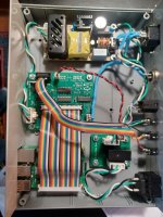
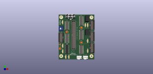
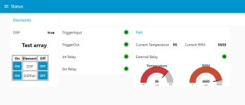
I'm posting this on the multiway forum because I designed this for a 3 way stand mount I made and converted to an active setup. I hope it can stay here because I think there might be some interest to others in this forum. Based on some advice I received on this forum I picked up a QSC Basis DSP on eBay and a multichannel power amp on Craigslist. The problem I needed to solve was powering on the the DSP because it has no 12V trigger input. Initially I put together a simple relay with a delay board I found on Amazon. It worked, but the delay board was a pain to program. So, since I started my career as an electronics technician I figured I can do better. At this time the Raspberry Pi 3B+ was cheap and readily available so I wire wrapped up a board to connect some relays to the GPIO bus. Little did I know at the time what was going to happen to electronic component availability and especially what happened with the Raspberry Pi. Once I had the prototype I solved the second problem I had, the micro fan in the DSP was very loud. To solve this I added an A2D chip to read the internal temperature of the DSP and replaced the fan with a 4 wire Noctua fan. Now since the fan has a tach output I added a frequency to voltage converter to read the fan speed. Finally I added more connectors to use all the unused I/O ports. All this is the usual project creep we all experience. At the same time I was learning Python to make this thing work, my programming experience had all been with assembler, C and C++ so my Python code might not look right to a Python programmer. I designed the code to be configured by editing json files or using a networked programming interface. Lastly I used NodeRed to build a web front end.
First off, I am not selling it, it is completely free to any body and I have documented it the best I can on my website. Now that Raspberry Pi are obtainable again I am releasing it to the community. I had 5 printed circuit boards made for each component, an I/O board, 5 amp relay board and 15 amp relay board. I have a few left and I will give them away. If you want a board stuffed with the electronic parts I am willing, but you would have to pay my cost for the parts. Here is a link to everything, BoMs, Gerber files, code and documentation. If you find any typos (well not if, when) let me know. If you you have any questions ask her, Pm or use the contact me on the website.
https://www.bellarossafabrica.net/av-power-manager
Attachments
Hello,
Very nice website. Inspired me to continue working on some projects I have going
Thanks
Jcris
Very nice website. Inspired me to continue working on some projects I have going
Thanks
Jcris
So did you introduce the Raspberry Pi only to provide a turn-on delay for the DSP ? No offence, but there are simple components like the following that are meant to provide a proper start-up for processors like these. Hope that helps.
https://www.analog.com/media/en/technical-documentation/data-sheets/MAX803-MAX810Z.pdf
https://www.analog.com/media/en/technical-documentation/data-sheets/MAX803-MAX810Z.pdf
I don't see how the Max803 will allow for multiple programable power on and power off delays. Am I missing something? I used the Pi because I had one and it was cheap at $30.00 at the time. I know it was a problem to get them for a while but I just bought a Pi4 with 2G ram for $45.00.
You could combine multiple MAX803s or use other very similar devices as in Figure 3 at the llink below:I don't see how the Max803 will allow for multiple programable power on and power off delays.
https://www.all-electronics.de/wp-c.../article-pdf/90063/433ag1211-maxim-an5040.pdf
No problem, I was just curious, that's all.I used the Pi because I had one and it was cheap at $30.00 at the time. I know it was a problem to get them for a while but I just bought a Pi4 with 2G ram for $45.00.
I see, the delays are set by capacitors. My goal was to be able to adjust the delays. To change the delays on the MAX16029 would require swapping capacitors. With a brief a search I found some Digital Programmable Capacitors, but they all require a two wire serial interface to change the values. To use these would still require a source for the 2 wire interface and a way to control that source. So I would still need at a minimum a micro-controller and the Pi has all the added features of WiFi, ethernet and a large community of user to user support just seemed to be the logical direction to pursue.
Why not just use an lm339 with a potentiometer and capacitor on the input? Your looking at ~$2 in parts.
I have already stated the reasons I did not just use a simple delay circuit but instead went the way I did. I wanted flexibility and a software defined way of changing delays and features. I looked at commercial products such as the Furman M8-S https://www.furmanpower.com/product/15a-standard-power-conditioner-with-sequencer/ and thought I would put together something more suitable for my use case.
Yes, such features require a suitable platform besides which there was a fan whose speed you wanted to control.... the Pi has all the added features of WiFi, ethernet and a large community of user to user support just seemed to be the logical direction to pursue.
- Home
- Loudspeakers
- Multi-Way
- An electronic device that I developed to sequence power and control 4 wire fans


