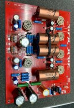
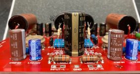
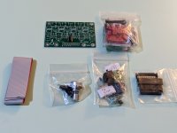
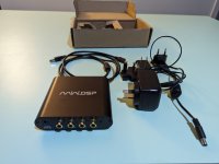
A Fun FAST project for Christmas break.

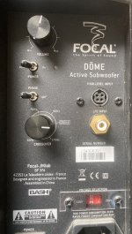
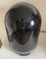
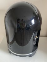
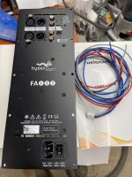
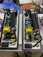
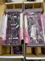
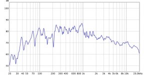
I'm planning a build over Christmas for a workshop Bluetooth speaker build around the Bru5 amplifier which has dsp. The brief is it's a fun project and not expecting hifi. It's gotta go load so can be heard over the machinery. The two channels I would like to run a FAST arrangement in mono if the software allows this. The full range will likely be the faital pro fe22 that often get mentioned but I'm not sure what subwoofer to go for. I would like it to be sealed due to saw dust. Something that doesn't mind being EQ'ed. Size of the cabinet and driver isn't a concern within reason but it's a budget fun project so not silly money. The fr driver is £20 the amp was £30 so if I could get a sub for £50ish so I've spent £100 that would be great. (Free wood for cabinet)

Campbell and Holtz Travelers plans

I am trying to find a speaker design to build, being capable with my paws but not being a speaker design Guru.

I hear good things and like the look of Curt and Jim's creations, but a number of the designs I like are either just too big for the room they are intended for (Statements / SII), or there are drivers in them that are no longer available.

I like the Finalists which are an older design, but I have recently discovered there is an update to them - the Travelers. From what little I can glean they would be near perfect for my needs. Trouble is the only place they and their plans seem to be available is Meniscus. Or rather was. I hope they enjoy retirement.

I can probably find the drivers and other hardware, even here in the UK / Europe, but without the plans for cabinetry, crossovers, a definitive list of drivers etc I am stopped before I even start.

So does anybody know where I could get the plans for the Travelers?

E8900

Can the 8900 be ordered preasembled without the Alps volume pot (plan to run it directly from IFI IDSD Pro)
If that’s possible, how much will it cost, shipped in the USA, as reviewed “Full Monty”by HA in the July issue of Stereophile (Lundhall+full AN upgrades+anything else that’s on VK mind for betterment of sound and life), with tubes other than GE?

Cheers

Linn Kremlin FM Stereo Tuner

On the desk I have the above mentioned FM tuner from Linn.
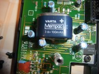
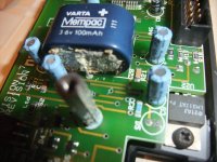
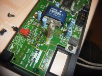
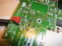
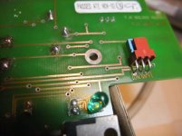
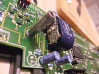
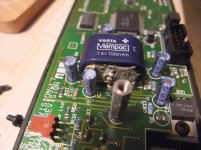
There is an oxidated area on the front PCB arround the 3V6 NiCd accu (memory cell) on the front PCB - go to the attachments so as to mpost #7 and #9 under
Linn Kairn repair
But the actually issue is the fact, this device has not been used for about 20-25 years. This means, that the electrolytic capacitors behind the rectifier must be soldered and reformed by a high-impedance resistor - go to
Reforming Electrolytic Capacitors
is there an other methody of this without the need to unsolder the big blue BHC caps ?
Thank you for advices.

Attachments

  • DSCF4371.jpg
    DSCF4371.jpg
    998.9 KB · Views: 541
  • DSCF4372.jpg
    DSCF4372.jpg
    1,004.4 KB · Views: 527
  • DSCF4374.jpg
    DSCF4374.jpg
    1,002.6 KB · Views: 498
  • DSCF4375.jpg
    DSCF4375.jpg
    992.4 KB · Views: 504
  • DSCF4377.jpg
    DSCF4377.jpg
    1,006.6 KB · Views: 517
  • DSCF4380.jpg
    DSCF4380.jpg
    995.5 KB · Views: 358
  • DSCF4385.jpg
    DSCF4385.jpg
    985.5 KB · Views: 349

Sundown SFB-8000D

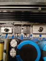
I had a Sundown SFB-8000D amp come into the shop yesterday that wasn't giving any output. The guy who brought it in said he bought it off some crack head on Facebook marketplace for a good price, but bought it knowing it was broken. Apparently the original owner was cutting out the transistors to the right of the ones pictured whenever one would blow and take the output out. Best I can figure he also cut the legs on the S5 and S6 ic's as well and soldered them back together.

My problem is Sundown decided in the factory to remove the original markings on the IC's and now I can't figure out what the transistor is supposed to be. Looking this forum I managed to find the missing transistors (which are labeled D1 instead of having part numbers) are IRFP90N20D and the driver IC's (which are also burnt up) are Irs20957s.

The transistors in the photo aren't testing faulty I just don't like the idea of taking all the time to source the missing and blown components and leaving these in in their current state.

I appreciate any and all help.

Attachments

  • IMG_20231112_162723700_HDR.jpg
    IMG_20231112_162723700_HDR.jpg
    409.9 KB · Views: 187

Yamaha A-1000 preamp sound quality

Hello 🙂 I am seeking advice with my yamaha a-1000. I am not sure if it is just my piece or it is standard behavior of this amp, but the sound from the stock preamp is really not nice. It has a really flat sound on mid/high frequencies. But the situation is completely different when I put the input signal directly to the main amp. It started to produce a really nice sound, not boring, not liveless, not flat. So I guess that is something not 100% allright with a preamp. I changed 4x caps (highlighted) on the preamp board. Also cleaned the DIRECT switch, MUTE switch and did measurement on other signal switches, all looks good. Both channels have the same ** sound, so I hoped that IC M5219L is not good, so I swapped it for another(from the main board) but unfortunately it didn't help. Voltages on IC are correct.

Input voltage to the preamp board is +21.5V and - 18.9V (should be +-22V). But I guess that this is not problematic because this is also voltage supply for the IC on the main board (main board sounds great, also on DBT when voltages are even lower).

What else should I try ? Change M5219L for something different (opa2604) and hope that will be better ? Throw a preamp (they call it flat amp, yes I agree 😀) in the trash and use just the main amp ? 🙂 Thank you for your ideas 🙂

Attachments

  • preamp.PNG
    preamp.PNG
    591.3 KB · Views: 236

Mu-follower vs two-triode stage in single ended amplifier with 12AX2-6N2P (PoC)

Hello I want to build a new amplifier using ECC83-12AX7-6n2Pev (all equivalent) and one 6L6GC in SE with GNF (no others please, because I have a lot of them).

I never played with mu-follower.

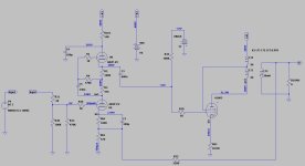
Can you please check if the mu-follower schematic is correct and which values you would suggest (using the above tubes)

Available AT is 320VAC so I think to get 400VCC.


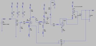
Second question: what about two ECC83 in series and a 6L6GC with GNF? It gives me a much lower THD% (second scheme) and a much bigger input sensitivity: should this sound better?


Thanks

Attachments

  • mufollower.jpg
    mufollower.jpg
    82.2 KB · Views: 173
  • two-serie-triode.jpg
    two-serie-triode.jpg
    88.3 KB · Views: 146

MJ Magazine (formerly Musen to Jikken) - Yearly Index from 1924 - 2009 wanted

This magazine, founded in 1924 by Mr. Mitsugu Tomabeji, is one of the earliest and most influential radio magazines that I know. In the early years it was Radio experimenter's magazine (Musen to Jikken = Radio and Experiments). The early publisher of this magazine was the currently brand ITO and the currently publisher now is Mr. Seibundo Shinkosha.
https://web.archive.org/web/2008101.../english/corporate-profile/history/index.html
In general this magazine is a DIYer magazine and is very technical but is full of great articles on electronics and speaker design, room acoustics, audio history, as well as reviews, news, show reports, etc.

Very great similarity I note to the french magazine 'l Audiophile from 1977 until 1989 - go for table of contents to
http://6bm8.lab.free.fr/Documentations/Revues/Audiophile/index-1977-1988.html
The table of contents (INDEX) I can get about compact disc's:
CD1: 43 editions from 1977 to 1988- Part I:
go to
https://web.archive.org/web/20100518094713/http://nicolas.davidenko.perso.sfr.fr/revue/revues2.htm
for information in detail. Please note, the kind of the magazine is changed from 1989 (now a normal testing magazine like "Stereophile"
CD2: 32 numbers from 1989 to 1995 - Part II

I want to have all articles about solid state pre-amplifier and power amplifier topologies published in this MJ magazine.
Where I can get table of contents about the MJ Magazine for download or as CD-ROM and what about translations in various other languages?

here various URLs:
http://www10.big.or.jp/~dh/sakuma/index.html
https://web.archive.org/web/2008120...ck/Texts/GeschlosseneGesellschaft/2-5-10.html
JSTOR: An Error Occurred Setting Your User Cookie
??¸ ?'75 Stereo Technic ???????? McIntosh/JBL/audio-technica/Jeff Rowland/Accuphase/?/?¾?????
??????/TOP???
Subscription information for "MJ"
http://www.fujisan.co.jp/Product/244
Patent US4079333
http://www.diyaudio.com/forums/swap-meet/129395-mj-audio-technology-magazine.html
http://www.diyaudio.com/forums/everything-else/136060-why-i-buy-mj.html

BTW - you will get very interesting cover images about google by follow japan keyword:
"無線と実験" (english: "Experiments with radio")

Various Siemens styroflex capacitors

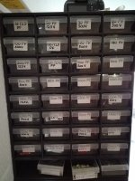
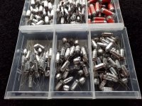
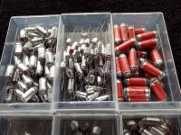
I'm offering theese capacitors, they are all NOS siemens, for sale, minus the cabinet, I'm unsure about quantity, but all drawers are like photos, can on request take more photos.
Asking price 150 euros, or trade with a lcr meter, DER.DE5000 or similar quality, fried my own by accident.
EU only.

Attachments

  • 20231007_085718.jpg
    20231007_085718.jpg
    363.6 KB · Views: 190
  • 20231007_085853.jpg
    20231007_085853.jpg
    476 KB · Views: 185
  • 20231007_085845.jpg
    20231007_085845.jpg
    493.4 KB · Views: 194

Small full range closed back vs open back without enclosure effect on audio

Hi,

My bookshelf tweeter was not working fine so i tried replacing it with same specs but instead of 2 inch I replaced it with 2.5 as my cabinet had more room also 2 inch was not available at that time.

What I noticed is my old tweeter had closed back means spider was not visible, were as this tweet has a open back i can see spider.

So will it make any issue like, moreover

woofer is in different compartment there will be not much air pressure only vibration is a issue they might interfere with my tweeter or not i don't know.

If it is bad so I can replace with closed back one or return this 2.5 inch tweeter and try finding closed back tweeter

Thanks in advance

Tannoy Chester T165 crossover

Hi,

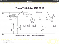
I’ve recently bought a pair of Tannoy Chester in really good shape, 2528 drivers in perfect condition. They sound great but there seems to be something wrong with the hi-end of the spectrum. Resonant/sibilant. After looking inside at the crossover and after some research about the n.1004 crossover I have found the attach schematic. Quite different from a lot of Tannoy crossovers.

The 2528 seem to have the same tweeter/diaphragm as the 2558 and a lot of other Tannoy drivers.

My plan is to build a entirely new crossover starting from the crossover of the srm12 that you can see on the second picture. The driver in the srm12 use the same tweeter diaphragm as the 2528. That’s the closest model that I have found the schematic online. The only modification to that schematic would be the use of a normal coil instead of the autoformer.

Anybody with some experience with this? Any recommandation/suggestion would be welcome!

Merci!

Hubert

Attachments

  • 5F5C4D7B-3998-4528-9E54-D5FC9D94BCD3.png
    5F5C4D7B-3998-4528-9E54-D5FC9D94BCD3.png
    559.7 KB · Views: 402
  • A5117ABB-75F7-4CC5-A269-F23215B4E413.gif
    A5117ABB-75F7-4CC5-A269-F23215B4E413.gif
    30.8 KB · Views: 410

Yuichi A-290 CAD files, modifications and BEM simulation results

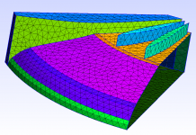
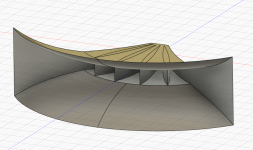
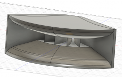
A few months ago, there were a few threads that rekindled my interest in radial horns and the Yuichi A-290 in particular. I wanted to make a BEM sim of the A-290 to see it’s directivity and if there were any simple modifications that might result in an improvement. I thought it would be a simple task of transferring the values from the document into a CAD drawing. This turned out not to be the case as the values from the drawings did not create a smooth curve for the horizontal sides. I chose to use a conic curve with a visual best fit between the points in Fusion. The radius dimensions to align the flat section with the fin ends and vertical expansion didn’t quite line up and I decided to fudge it to make it work. The dimensions for the fins produced reasonable curves without any intervention. The original file had the sides being quite flat before curving out as this seemed to match with images of completed horns, I had seen.

I was able to make a mesh and get a basic simulation going. There were a few problems with the model but overall, the directivity seemed to be reasonably constant in the horizontal as touted. The Radiation Impedance was very spiky and odd looking and looked to me like it could be from simulation errors. I knew @DonVK had simulated some similar horns with @docali so I got in touch with Don to have a look and see if he could offer some advice on what I was seeing. It turned out that there wasn’t too much wrong and that the Rad Imp was reasonably consistent with other horns of the same type.

This sparked off several different simulations to improve the model and look to improve the horn without making it into something completely different. Don made all the model iterations. Ideas on fin placement and number from Kolbrek and Dunker’s book were tried along with asymmetric, golden ratios and some other variations. The results iteratively got better and in tandem docali’s Radial Fin spreadsheets were reworked by him and simulated by Don looking for improvements. The horn’s resulting from docali’s spreadsheets surpassed the best attempts at improving the A-290. As a result of lessons learned there, I took another look at the A-290 documents and reworked the CAD from scratch. I drew three-point arcs based on defined coordinates from the drawings for the side profiles and used the data taken from the excel spreadsheet calculations (included in the A-290 doc) for the vertical curves. This time the fin ends lined up exactly at the end of the flat section and the overall result was much cleaner. The best result for a horn based off Yuichi’s plans used 6 fins with a spacing of 7.5,15,15,15,7.5 degrees. The outer two channels being half fins between the fin and wall.

It is still not clear to me if there is a definitive way to produce an exact A-290 as Yuichi intended. What you can find in the attached step and Fusion archives is the blueprint to build either of the versions I created with simulated performance of what to expect.

The V1 is a full 3D solid model, the V2 is a surface model that needs further work to turn it into a full 3D solid for production. Results of selected models to follow in further posts.

Greater simulated performance can be had from similar horns and the information may be released in another thread describing that process or via docali’s sphericalhorns.net website, currently those experiments are still ongoing.

Attachments

  • A-290 V1.zip
    A-290 V1.zip
    451.6 KB · Views: 527
  • A-290 V2.zip
    A-290 V2.zip
    553.2 KB · Views: 457
  • A-290 Qtr Mesh.png
    A-290 Qtr Mesh.png
    63.8 KB · Views: 724
  • A290V2 - Surface.png
    A290V2 - Surface.png
    140 KB · Views: 640
  • A290 V1 3D.png
    A290 V1 3D.png
    99.9 KB · Views: 786
  • A290-V2-3 H Polar Norm.jpg
    A290-V2-3 H Polar Norm.jpg
    30.8 KB · Views: 714

For Sale Bones13 Sell Off - 2

Bones13 Sell Off -> SOLD OUT

I have finished my last project - an n channel VFET amp, which shares duties with a SissySIT r3.

Eyes are going, fingers less nimble, and looking to move across country, and won’t have the space that I enjoy now. I am selling many of these for shipping costs (rounding up and down to $10) Charging half as much for the SITs and VFETs to benefit the community. I bought from proven vendors, but have not tested these.

Anyway, I am going to unload a bunch of boards, VFET/SITs, unstarted and a mostly finished kit. All Vets were purchased from Spencer at DIYCircuit. SITs were obtained from Tomoaki Watanabe.

I am aiming to help the DIYAudio community, but I will prioritize requests from the people who have helped me in the past. Not doing a lottery like the initial VFET sets, but if you don’t have many posts, you will go down the list below folks I know for here, or see that are active here.

Finished boards
1 pair F6 boards, with only the MOS chips unmounted. ($50+$10)

Kits - not started
2 x Reflector power supply boards, and parts ($15+$10 / each)

Boards
1 pair P VFET OS2 boards, with pair of 2SJ28 ($75+$10)
1 pair N VFET OS2 boards, with pair of 2SK82 ($75+$10)
1 3-board set of Pequot Daughter boards ($10)
1 3-board set of Bon Homme Richard boards ($10)
3 single TUBA Boards ($10 / each)
5 single H9KPXG-C push button, slow start switch boards ($10 / each)

(3 will have the SMPS and SL22 parts)

Transistors
1 pair 2SK182E SIT ($50+$10)
1 pair THF-51S ($50+$10)
4 2SK180 (looks to have been recovered, sold as set for shipping $10)
1 pair Sony 2SJ28 ($50+$10)
3 pairs Sony 2SK82 ($50+$10 / pair)

VFET + Boards.jpg
  • Like
Reactions: Cindra and dBel84

For Sale Hypex FA122 Plate Amplifiers - $700 for the pair

For sale is a pair of Hypex FA122 plate amplifiers. These have been lightly used and are in excellent condition. I bought these for a powered monitor project but decided to go in a different direction.

These are 2 x 125 watts with digital and analog inputs. Easy to use and program with the Hypex software.

Original packaging, speaker cable, and instruction manual included.

Asking $700 for the pair. I will cover shipping and PayPal fees at my asking price.

Thanks for looking and please let me know if there are any questions.

DaveJ

Attachments

  • FA122, 1.jpg
    FA122, 1.jpg
    936.2 KB · Views: 91
  • FA122, 2.jpg
    FA122, 2.jpg
    841.5 KB · Views: 86
  • Hypex, 3.jpg
    Hypex, 3.jpg
    841.8 KB · Views: 95
  • Hypex, 4.jpg
    Hypex, 4.jpg
    850.2 KB · Views: 94
  • Hypex, 5.jpg
    Hypex, 5.jpg
    788.8 KB · Views: 97

Merlin VSM issue: advice for a newbie

Hi,

I just bought a pair of the "mythic" Merlin VSM.
I'm a newbie and measurements and I would like some advice please.
A good friend and member of this parish gives me his thoughts, and I'm looking for other ones to confirm.

First of all, I'm not a pro in measurements, first time. Measurements have been done using REW+UMIK (calibrated then).
1 m, tweeter AXIS, mike between tweeter/woofer.
In room, no window.

Issue: when I came back home, plugged the speaker I directly felt something wrong in highs. Nice bass, nice medium, too much medium not enough highs.
They have the Esotar tweeter, supposed to be one of the best, so disappointing ;-)

OK enough blabla, find some graphs below, and please don't hesitate to ask me other or teach me how to make it right.
My goal is to understand what is wrong. Tweeter or crossover?
Thanks

So you have both of Merlin (2+3)
I sent a 5000Hz signal to tweeter to check SPL
I compared with my Sonus Faber Electa Amator II using the same boomer.

Attachments

  • Merlin 2.jpg
    Merlin 2.jpg
    68.6 KB · Views: 153
  • Merlin 3 .jpg
    Merlin 3 .jpg
    74 KB · Views: 148
  • 5000.jpg
    5000.jpg
    104.2 KB · Views: 155
  • Merlin vs Sonus.jpg
    Merlin vs Sonus.jpg
    83.8 KB · Views: 160

Pilot 610 project

I have this Pilot FM receiver that I obtained ... somewhere, mant years ago. I want to add music to my basement workout space, so I picked this off the shelf as a candidate.

Pilot610front.jpg


Pilot610back.jpg


Pilot610under.jpg


Surprise to me, it looks entirely virgin. Original cover, original screws, only dusty. Push-pull 6GW8s may have been replaced, but the rest of the tube complement is Tele and Mullard marked "Pilot."

I could go ahead and do the usual gentle ramp-up and testing, but I'd feel more comfortable with a schematic, or Sam's or something. Anybody have a source?

tia Tim

Two interesting documents. Current Drive Amplifiers and How Amplifiers Treat Big Signals

I came across these two papers from John Woodgate and surprisingly can not find any reference to them on the forum... so here they are. The current drive paper will be of interest to many I'm sure.

Attachments

Woofer suggestions needed for 6L PR enclosure

Hello all,

I'm in the process of designing/making some high end-ish speakers. The problem is that I'm kinda designing them backwards as in I have some cool looking vintage cabs that have 6 liter internal volume so I have to pick my drivers according to that. For tweets i have settled on some Morel CAT 408s and for woofers I was looking at Morel ECW 536 but was wondering If some of yall with more experience could perhaps suggest something better for my goal which is for the speakers to go as low as possible and sound good while doing it. Budget is flexible. Thanks.

vintage Nordmende output transformer

Good morning:
I have been going through my collection of salvaged output transformers trying to set up a new project. I came across a few of these transformers and am curious about them.
I did a turns ratio measurement and ended up at ~ 14k and 1.8k based on 8ohm speaker loads. These transformers came from a SE ell80 radio console.

My request is:
Can someone translate the wording on the attached diagram?

Can some help me determine what will be a reasonable tube to chose for these. The reflected load seems a bit high for most of the common tubes I am familiar with.

I suspect they are in the 2-3 watt range so Flea Power seems in order.


1671035604893.png


Thanks for the help

SB Acoustic TL-MTM build (cabinet advice)

Hi, my name is Frane, Croatia.
Im building TL- MTM:

Woofers: SB16pfcr25-8
Tweeter: SB26adc
(5" augerpro waveguide)

Initial idea was to make sealed tower enclosure based on Grundig Sl1000 MTM topology from 1978. To this date best sounding speaker I've listened to - only "flaw" are 4" woofers. It is suited only for smaller rooms. (And yes - I've heard likes of Magico, PMC Fenestria etc)

However I got interested in idea of transmission line because it offers best of ported and sealed enclosure. But I never heard one, nor built one - just know some basics.

I read lot of stuff few last days on MJK site, however his MathCad sheets are not available anymore. So I started playing with Hornresp, analysing available designs. For example example TrixTrix TL and Dappolito's Thor..

What I have found is - when modeled in Hornresp - those enclosures seem to be tuned 10-15hz lower than Fs of the driver.. and that is without the stuffing which brings the tuning even 5-10hz lower.

From available information for a lowish Qts (0.35-0.4) driver tuning should be slightly higher than Fs, yet every available design I try to model seems to be tuned waaay waay lower. Even when using TL calculator on Hornresp (MJK models) with SB16pfc parameters automated tuning is always much lower than fs.

I will most likely design something like trixtrix short folded tl enclosure because it behaves well in sim, unlike Thor with its 2m long line and small offset..

My question would be.
How low should you tune TL and not run into the problems?

Any ideas and suggestions for enclosure are welcome.

filaments: SNR values for AC/DC?

Hey folks, I know that versions of this question have been beat to death so pardon me. I am having trouble finding metric data and wondering if anyone could help me understand.

I have built amps with clean, tight AC heater wiring and not had too much of a problem. I also have some of the Pete Millett DC boards and I've done some basic DC regulators now.

My question is this: in terms of noise / db / however I should be looking at this, what is the actual noise difference between properly twisted AC and properly regulated DC on a tube filament?

Also: I am not concerned with filament life, electron migration, etc etc. I'm specifically looking for information about lowering my noise floor.

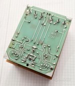
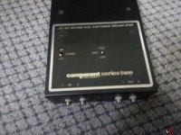
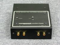
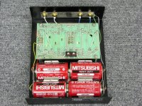
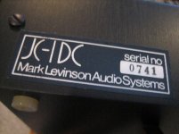
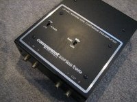
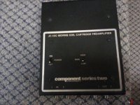
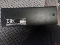
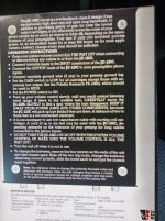
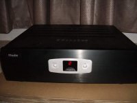
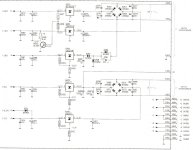
Mark Levinson MC Pre-Preamplifier JC-1 (JC1) - how many Versions at whole are there

Until now I know this Versions:
1) JC-1
2) JC-1DC
both made for battery only and for both the schematic I have - go to this threads:
https://www.diyaudio.com/community/...etween-mark-levinsons-jc-1-and-jc-1dc.243267/
www.diyaudio.com/community/threads/mark-levinson-jc-1dc.372134/
https://www.diyaudio.com/community/...rom-mark-levinson-for-jc1-resp-ro-iii.242541/

But in the meantime I have discover further for me unknown versions:
3) JC-1SM (JC1-SM)
4) JC-1DC series two
5) JC-1AC small power supply
6) JC-1AC high current power supply
7) JC-1 with integrated transformer (maybe a clone of one from previous mentioned)

Who have the associated schematics for this versions ?

Attachments

  • JC-1 SM-IV.jpg
    JC-1 SM-IV.jpg
    102.4 KB · Views: 163
  • JC-1 SM-VV.jpg
    JC-1 SM-VV.jpg
    155.5 KB · Views: 173
  • JC-1 SM-V.jpg
    JC-1 SM-V.jpg
    86.2 KB · Views: 170
  • JC-1 SM-III.jpg
    JC-1 SM-III.jpg
    235.4 KB · Views: 156
  • JC-1 SM-II.jpg
    JC-1 SM-II.jpg
    241.5 KB · Views: 174
  • mark-levinson-jc1-dc ser.-two-top-III.jpg
    mark-levinson-jc1-dc ser.-two-top-III.jpg
    116.9 KB · Views: 149
  • mark-levinson-jc1-dc ser.-two-top.jpg
    mark-levinson-jc1-dc ser.-two-top.jpg
    86.6 KB · Views: 158
  • mark-levinson-jc1-dc ser.-two-rear-III.jpg
    mark-levinson-jc1-dc ser.-two-rear-III.jpg
    61.8 KB · Views: 154
  • mark-levinson-jc1-dc ser.-two-open.jpg
    mark-levinson-jc1-dc ser.-two-open.jpg
    139.1 KB · Views: 165
  • mark-levinson-jc1-dc ser.-two-rear.jpeg
    mark-levinson-jc1-dc ser.-two-rear.jpeg
    22.3 KB · Views: 155
  • mark-levinson-jc1-dc ser.-two-top-II.jpeg
    mark-levinson-jc1-dc ser.-two-top-II.jpeg
    30.3 KB · Views: 133
  • mark-levinson-jc1-dc ser.-two top-IV.jpg
    mark-levinson-jc1-dc ser.-two top-IV.jpg
    120.1 KB · Views: 138
  • mark-levinson-jc1-dc ser.-two-rearII.jpg
    mark-levinson-jc1-dc ser.-two-rearII.jpg
    94.5 KB · Views: 175
  • mark-levinson-jc1-dc ser.-two-review.jpg
    mark-levinson-jc1-dc ser.-two-review.jpg
    67 KB · Views: 143
  • mark-levinson-jc1-dc ser.-two-botton.jpg
    mark-levinson-jc1-dc ser.-two-botton.jpg
    103.8 KB · Views: 144
  • JC-1SM top.jpg
    JC-1SM top.jpg
    40.2 KB · Views: 171

For Sale Duelund Interconnects/speaker cable

Needed a new project 😊 so I decided to re-cable my system so
1 pair 16' factory built Duelund interconnects with no plastic RCAs - $235 (less than price of RCAs
2 pair 6' factory built Duelund interconnects with no plastic RCAs $200/pair (less than price of RCAs
2 12' twisted pair speaker cables 12awg - no connectors $ 60
I will cover CONUS shipping

Streaming through Windows 10

I stream Spotify through a W10 computer to several DACs. one of these is an ifi Zen Dac V2 which is capable of handling DSD and I also have a Topping D30 which also takes DSD. I can go into the W10 sound settings and on Playback choose which rate I want to listen to e.g 24bit 192khz or lower or higher.

If I do this with the Zen the LED shows it is receiving a DSD signal due to the colour of the led. Am I being tricked or does W10 upsample the feed from Spotify and if not what is happening?

WAF Tales

My wife is very understanding of this and other hobbies. Periodically she asks "How many oscilloscopes do you have now?". The number always creeps up. She being a molecular biologist takes this in stride as the academy is filled with such nut-cases as myself.

But this story relates to #3 son who was moved from the West Coast to the North Coast (yes, the sun will come out in April). She is somewhat less accepting of our mutual devotion.

In their new house, he arranges the living room furniture (in contravention to the recommendation of the interior decorator) for an ideal listening position in their family room. (The prior design had two couches facing each other with no room for the JBL 300's.) Another silent wifely commandment is that "There shalt not have any false cables lying on the living room floor before me". He goes on a client visit to Canada for two days and finds that the decorator's instructions have been effected.

What is grandpa to do?

Strange dip in low-end response

So I got around to a project I have been wanting to do mainly for fun: build a larger floorstanding speaker.

But not just any floorstanding speaker - I wanted to try a ported design.

I had this so-so Focal woofer laying around from a component car audio set. Not the greatest thing in the world - but half-decent.

The bigger point of this project was: expiriment with WinISD. I have always built sealed enclosures - ALWAYS. I thought.. why not try a vented enclosure with this little driver just for the fun of it?

Basic Driver specs are:

6 inch woofer
4 ohm
FS = 58hz
(I can post all the TS params if needed)

I measured the TS parameters with Dayton DATS (v3). The specs were pretty close to the factory stated details. And YES, this woofer had a LOT of prior break-in.

So... I went through the tutorial for WinISD. Plugged in the TS params for the woofer. Started a new project: Vented. And off I was - playing around with the numbers.

I found that - according to WinISD - I could set the tuning frequency at 36hz and stay within (less than) 3db all the way. I choose a 2.2 sq ft enclosure and was told (by WinISD) that if using a 3 inch port, it would have to be 4.45 inches long. Done and done.

That was my assumption - and what WinISD showed me.

First - the good news: the bass is DEEP. Surprisingly deep. I actually would say it was a great success except for... I noticed certain songs with various bass notes just did not sound right. So I started to measure.... Somewhere between 52hz and 54hz I get a dip. And by dip, I mean - easily 12db (or more) down. Like... you can clearly see the cone is vibrating hard, but almost hear NO SOUND AT ALL. This only happens within this very narrow band. Below 52, it is solid down to 32hz (lower than the WinISD simulation!). And above 54hz, all is normal.

A tiny 2-4hz gap where sound literally goes mute.

My theory is: this has something to do with trying to push the driver too far below the FS? Perhaps I should have tuned this for something higher?

Perhaps some sort of box resonance?

If this IS likely what happened, could someone give me some pointers when tuning a vented enclosure in regards to the tuning freq and the driver FS?

This project was my first time playing around with vented enclosures like this - and was primarily to get my feet wet.

I am certainly impressed with the results for the most part. I just want to be sure I do not repeat the issue that turned up above.

My next project is moving my dual (sealed) Dayton 15 inchers into a proper dual vented setup. Their FS is something like 19 or 20hz. I have WinISD simulation showing that I can tune the enclosure for these at 14hz with a 14 cu ft box. But after the above, I am worried that this may be too low (??).

-Dean

Thule Audio Vintage Integrated Amplifier IA-120 (IA120) Schematic wanted

Today I get a very fine sounded vintage amplifier for service: the IA-120 (see jpg attachement)

It was sold at a time when the German distributor for Thule Audio was still the same company that at the same time sold the loudspeaker brand ETON (LPG, Neu-Ulm). Approximately between 1984 and 1990.

Perhaps one of the members can post a PDF schematic - Thank you very much

Attachments

  • Thule PA350B.jpg
    Thule PA350B.jpg
    29.5 KB · Views: 1,557

Why many amps use a buffer at input stage?

Many amps use a buffer so they can be used in balanced mode to unbalanced to the first stage
The input stage is often not so low impedance so most preamps could drive the amps without these buffers
Why many manufacturers still use buffers often made with cheap op amps to good circuits ?
Is it only a commercial fashion to use XLR inputs which in reality is not a totally balanced amp ?

Thanks

Do crossovers change ohms with multiple speakers wired in parallel?

I've search high and low for answers and mostly just got more confused. I finally decided to just make an account and ask it myself. So... Hello everyone!

Let's say I matched the number value for impedance all around with a 3 way crossover and 3 speakers. So, one 4 ohm woofer, one 4 ohm mid range, and one 4 ohm tweeter all wired to a 4 ohm 3 way crossover. Will that act as 3 speakers wired in parallel and produce a load of 2 ohms on the input for the crossover?

My actual intentions are to wire two 8 ohm woofers in parallel, two 8 ohm mids in parallel, and two 8 ohm tweeters in parallel to a single 3 way crossover. Will that result in a 4 ohm or 1.3 repeating ohm load on the input of the crossover?

I already have the six 8 ohm speakers, I need a crossover and my radio is 4 ohms.

I know I can use everything as is because ohm ratings are a minimum so the 8 ohm speakers won't damage my radio. But, I'm using a car stereo and a pc power supply as my radio so I only have 50 watts per channel that I want to make the best of. The 8 ohm speakers I have are low power/quality and this radio should be plenty for them even if they're all all wired up in parallel.

Any help will be very much appreciated!

Harbinger Class D Amp with Crossover - No Output

DIYaudio Members:

My friend asked me to look at his Harbinger Powered Speaker. It uses a mono Class D amp with the IRS2092S amp module. Currently, there is no output. I am hoping Harbinger will send me a schematic. The output seems to be going to a Second Order Crossover that is on the Power Amp / Power Supply Board. I am looking at generic schematics for the IRS2092S but there seem to be differences.

The Low Speaker output has 40 volts dc on it. So there is an issue. The two Mosfets tested good. The board also uses a TIP41C NPN transistor - also tested good.

The Power Supply is your traditional Transformer, Bridge Rectifier, two caps. The plus and minus 50 volts are working. I am not a Class D expert but it seems rare that this Class D amp is not using a SMPS.

Any ideas on troubleshooting or trying to find a schematic that might be close to this particular unit?

Thanks in advance, Tom

Philips CD100/101 , Marantz CD63 overheating problem

I had two of those players and they were working fine but this one keeps overheating after an hour or so and the laser power supply goes down. It works fine without bottom cover. Before I start changing Regs and PTC resistor maybe somebody had similar problem with this family of players ?

Attachments

  • CD63_power_supply 001.jpg
    CD63_power_supply 001.jpg
    58.2 KB · Views: 96

HK870, 50v DC on speaker terminals

Bought with blown right channel, all 4 outputs blown. Pulled blown outputs, bypassed with 1k resistors to track voltage. Wouldn't leave standby. Replaced some bad components, still standby. One transistor on the driver board and the two caps in the protection circuit, out of protection, 15mv offset on right. 50v on left. Shut it down immediately. Outputs still okay on diode check, I don't have another set, so being very careful.
Where do you start on something that far out of wack? Going to bypass the outputs and start checking the circuit again. Seeking a bit of advice.

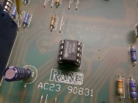
Restore and upgrade crossover Rane AC23

HI, I bought an analog electronic crossover, i.e. non-dsp, Rane Ac23.
It has a couple of power caps that are a little swollen, so I wanted to change the 6 power caps there.
The power supply has a voltage multiplier. 10.5+10.5vac enter the crossover (external transformer) which are multiplied by two and then pass through the 7815 and 7915 regulators. The crossover operates at dual voltage +-15vdc.

Do you think I can use Panasonic FC for all 6 capacitors even if in different positions?
I attach the diagram.

I ask because I seem to have read that low ESR capacitors, downstream of the regulators in question, can generate oscillations or, in any case, not be optimal.

Also I wanted to ask why the TL072s are on sockets and the other OPs are not.
I would also like to upgrade the OP, many years have passed since its production and perhaps there is something better.
Does it make sense to just change the TL072s on the sockets? Or would it be necessary to also put sockets on the other dip14s and mount other OPs?

I would also like to eliminate the subsonic and ultrasonic filter.
I attach the diagram.

Thanks for any help.

Attachments

  • ALIMENTAZIONE.jpg
    ALIMENTAZIONE.jpg
    92.4 KB · Views: 287
  • SCHEMATIC 01.pdf
    SCHEMATIC 01.pdf
    978.7 KB · Views: 169
  • SCHEMATIC 02.pdf
    SCHEMATIC 02.pdf
    884.1 KB · Views: 137
  • 20231108_153756.jpg
    20231108_153756.jpg
    535.9 KB · Views: 244
  • 20231108_153811.jpg
    20231108_153811.jpg
    347.1 KB · Views: 242
  • 20231108_153819.jpg
    20231108_153819.jpg
    342.6 KB · Views: 247
  • 20231108_153826.jpg
    20231108_153826.jpg
    374.4 KB · Views: 226
  • 20231108_153842.jpg
    20231108_153842.jpg
    344.5 KB · Views: 371
  • 20231108_153848.jpg
    20231108_153848.jpg
    312.5 KB · Views: 229
  • 20231108_153903.jpg
    20231108_153903.jpg
    335.2 KB · Views: 227

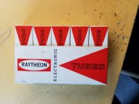
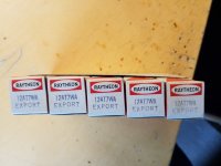
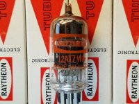
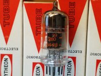
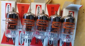
12AT7WA tubes

Hello..
Just stumbled over theese very nice and unused Raytheon tubes.
I have no real interest in tube audio and would like some offers.
Black plates and tripple mica.
Took all careful out to photograph, same batch all

Attachments

  • 20231112_124624.jpg
    20231112_124624.jpg
    290 KB · Views: 93
  • 20231112_124643.jpg
    20231112_124643.jpg
    241.4 KB · Views: 95
  • 20231112_124826.jpg
    20231112_124826.jpg
    385.3 KB · Views: 84
  • 20231112_124854.jpg
    20231112_124854.jpg
    389.6 KB · Views: 79
  • 20231112_131504.jpg
    20231112_131504.jpg
    368.7 KB · Views: 82
  • 20231112_131534.jpg
    20231112_131534.jpg
    366.3 KB · Views: 79

For Sale Electronic Instruments for sale - pickup only (Germany), sorry

A friend of me passed away some time ago and now I help his wife to dissolve his workshop.
She is not able to ship adequately, so pickup in Kerpen/Germany (near Cologne) is possible only.

As far as I know, these devices are all in fully operable condition

Rigol MSO2302A Oscilloscope 2Ch. 300MHz 2GS 350€
Panasonic VP-8193A AM/FM-Signal-Generator 350€
Two older PSUs 10€
Distortion-Meter 20€ reserved
Siemens D2002 Function Generator 20€ reserved
Hameg HM1005 Oscilloscope 2Ch. 100MHz analog 40€


Rigol.jpeg


Panasonic.jpeg


PSU.jpg


THD-Meter.jpg


FunctionGen.jpg


Hameg.jpg

DIY add on Input stage for Class D module

I recently built a class D dual mono amp from (2) Icepower 1200AS mono amps. It's my first experience with class D. I went from an Adcom 5802 to this. They couldn't be further from each other in sound. The Adcom 5802 was all weight and overly fleshed out and a little on the dark side with my 12" + 15" combo and the Icepower is big fast and light. Almost too thin and quick. I was watching Paul McGowan's, from PS audio, recent video on "Stereo vs Mono amps" and he was showing off their input stage (w/ tube) for the exact same module that I have. He said that it "was where the magic happens" with their amp. I want to bring back some of the weight and flesh out the bass a little more than what the 1200AS is doing. I don't want to copy/steal what PS Audio has but is there something along those lines out there? It doesn't really have to have a tube. I'm more interested in sound but a tube is fine too. Thanks

For Sale Audio Note L1 (Clone Board), Fully Constructed

To sell 1 fully constructed board for Audio Note L1 EL84 amplfier

Please have a look at the photos.

Amongst other very good components:
- Nichicon Audio Capacitors, B+ filter
- Elna Silmic II
- Black Gates on the EL84 Cathodes
- Audio Note Tantalum resistors in some specific places
- Audyn Copper Max Signal capacitors
- Mills resitors

Fully working, and tested.

If you want to build a full amplifier, look to my other threads for the power transformer, Lundahl output transformers, EL84 Tubes, ECF80 Tubes.

Price 350€ + Shipping (please consult).

I accept Paypal.

Attachments

  • AN L1 1.jpg
    AN L1 1.jpg
    127.4 KB · Views: 910
  • AN L1 2.jpg
    AN L1 2.jpg
    75.4 KB · Views: 857
  • AN L1 3.jpg
    AN L1 3.jpg
    74.6 KB · Views: 812
  • AN L1 4.jpg
    AN L1 4.jpg
    119.8 KB · Views: 873
  • Like
Reactions: pompiliu

A tweeter choice Yet, advices needed!

Hello,

Any idea guys for a silk tweeter 2000 hz XO ; > to 90dB/2.83V ; as detailled as the metal SB26CDC to challenge it, please ? Budget less than 250 euros/USD max the pair

MTM with 5" hard paper units (NE149W).

I thougth about to the Bliesma T25S or the wave guided Morel CAT378/TW30A11 ? SS 2604/83000 ? small Illuminator twweter cans ? SB26STAC ( a liitle hot maybe in the highs and not liking too much low cut off as many SBACOUSTIC SB26)
Can be horned too but not sure it is worthing with 5" woofers ?!

Coming from daily aluminium tweeter use I am looking for something detailled enough and blending fine with a detailled papaer cone at the level of a Satori paper driver.

I wanted initialy a compression driver for its dynamic behavior but gave up the project for a 3 ways with 2 5" MTM for the medium area.

Thanks for your thoughs.
  • Like
Reactions: motokok

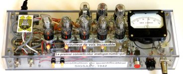
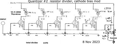
Recreation first analog to digital with 1942 Thyratron tubes

Bonjour, just got a new set of matched 1953 vintage RCA 2050 Thyratron Argon tetrode tubes.

Installed into the SIGSALY Quantizer ADC recreation, now calibrated perfect 6db/step CAL.

From my IEEE Spectrum Feb 2019 article.

Your thoughts appreciated.

Jon

Attachments

  • Quant2c.jpg
    Quant2c.jpg
    326.9 KB · Views: 167
  • Q2quantNOV23.jpg
    Q2quantNOV23.jpg
    173.7 KB · Views: 161

For Sale TAD TD4001 Pr, SEAS L26ROY Pr, Stax L300, Ortofon Cadenza Red, B&C DCM50, Markaudio MAOP 11

Selling the following audio equipment:

-Pair of TAD TD4001 Beryllium Diaphragm Compression Drivers -- Mint: https://www.ebay.com/itm/276137126769
-Stax L300 Earspeakers -- New: https://www.ebay.com/itm/276143706880
-B&C DCM50 -- New: https://www.ebay.com/itm/276130266031
-Pair of Mark Audio MAOP11 Drivers -- Sold
-Pair of Seas L26ROY 10" Subsoofers -- Sold
-Ortofon Cadenza Red -- Sold

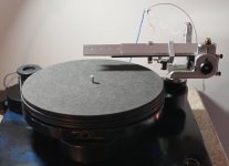
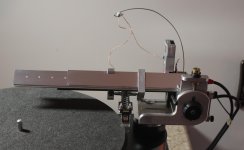
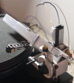
FS: Trans-Fi Terminator linear tracking air bearing tone arm

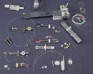
This is a complete package, which includes absolutely everything to operate the tonearm - the complete tonearm itself, the wands to hold cartridges, air pump, smoothing tank, extra tubing, extra wires. You will get 6 wands to mount six different cartridges. You will get extra wire to connect the cartridges to Molex connector. You will get the "VTA on the fly" gauge, if you are really picky about that parameter. You will be amazed how much better it tracks the grooves than most pivoted tonearms, no matter the cost. There will be no inner groove distortion, and no need to futz around with protractors.
The only thing that you will possibly require is the mounting column, depending on the thickness of the platter on your turntable. Any machine shop can make you one, if you need one that's longer that I'm including.
Cartridges and the turntable are not included, they are shown only for reference purposes.
The tonearm is ready to be assembled, provided you will have the proper height mounting column. Don't be freaked out by all the little weights, wires and screws: these are all just extras, that you'll probably never need.
Set-up instructions are very easy for those with modicum of mechanical sense, and are available on the TRANS-FI website.
Trans-Fi Audio - MANUAL

$XXX includes postage in the USA.

SOLD

Attachments

  • IMGG2824.jpg
    IMGG2824.jpg
    587.7 KB · Views: 366
  • IMGG2832.jpg
    IMGG2832.jpg
    551.1 KB · Views: 353
  • IMGG2852.jpg
    IMGG2852.jpg
    1,005.8 KB · Views: 408
  • IMGG2826.jpg
    IMGG2826.jpg
    405.4 KB · Views: 371

Output impedance measurement - without load?

Hey everyone,

I would like to measure Zout of my amp. This requires measuring voltage at the speaker output with and without a load.
Now I've always been told that a working tube amp always needs a load. See my problem (?) here?
Would it be okay to have a dummyload at the output, measure the voltage and then briefly disconnect that dummyload? One second should be enough.
I'm not sure...

DC-DC Converter (Switch or linear) Help (Lowest Noise Possible)

Hey there everyone!

New to electronics in general, but need help with an issue I'm facing for a personal project. Anything that could help would be much appreciated!

I'm trying to design a circuit that boosts DC to DC cleanly in the power section for an audio preamp I'm working on (500 series).

The preamp portion of the circuit is sort of plug and play as I've used it on other designs but the power section is what is hindering me from continuing on!

Now, I'm wanting to start with a +/-16vdc input in the actual real world application. (Variable input of something like 12-24v would be even better here!)

I need the output to be able to achieve a steady 400vdc or as steady as it can be. (Variable output up to 450v, 500v would be awesome too!) (CCM maybe?) (I don't know what I don't know)

The current doesn't matter much to me. Maybe like 5-20ma in the 400v range roughly.

Should I go with a boost converter? Flyback Converter? Do I use a high frequency transformer? Etc.

The only stipulations to my idea are:

not a ton of space to work with (500 series PCB for power and preamp circuits on final design).

I need it to be the cleanest output at 400v as I can get (minimize ripples).

Even if just providing schematics and parts that work on paper I can do all real world testing and man hours myself.

If you could work with me in anyway with a schematic and some parts that could be used for this, it would be so very much appreciated!

I've been all over asking for advice to no avail.

Thank you all, I hope we can all work on this 🙂

DIY Raspberry Pi KIT for Music Server / Streamer / Player / Digiamp (R23-MAX)

* SOLD *

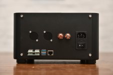
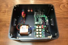
Hi, I'm selling another new Raspberry Pi DIY KIT. The KIT includes all of the necessary parts to build a Raspberry Pi Player / Streamer with built-in linear power supply. You will need some basic soldering skills and it takes at least 2 hours to assemble the parts. There will be an extra 7% for PayPal service charge. Shipping cost will be incurred depending on destinations. (I truly understand the shipping fee would be a bit high, but the case is made of 5mm thick aluminum, it weighs 4.6kg)

Usage of the KIT:
-Digital transport / streamer, supports Spotify, Tidal and Qobuz
-Media server with an internally mounted 2.5" SSD (not included)
-Digital to Analogue Converter with I2S DAC HAT
-CD player / ripper with an external USB CD drive (Volumio premium user only)
-An 25W/ch Class-D amplifier (Need to install an 80VA power transformer)
-Supports mainstream audiophile OS including Moode Audio, Volumio, piCorePlayer and DietPi
-Ropieee is NOT supported

Case:
-Aluminum alloy fabricated with mixed CNC and LASER cut
-All black anodized matte finishing
-7" HDMI QLED touch screen
-Can mount an 2.5" SSD internally
-Opening at the bottom, can change OS with ease
-Dimensions: 250(W) x 230(D) x 150(H)
-Support standard D-type sockets
-RCA jacks included
-Native support for Allo Boss 2 DAC HAT

Power:
-40VA audio grade R-type transformer, 5A output
-Built-in LPS, 1% load regulation, 80dB PSRR (120Hz)
-8x Nichicon FW Series capacitors
-Ultra low ESR, CLC filtering topology, WIMA MKP10 for final decoupling

Price:
HKD2300 (~USD293)

Shipping Cost (for reference only):
US: HKD780
UK: HKD471
Other countries: (Please PM me for more details)

********************************************
Note:
Supports Raspberry Pi 4B ONLY
Touch screen is included
No Raspberry Pi or DAC included
********************************************

YouTube demo:


Login to view embedded media

Work as a digiamp:


Login to view embedded media

BOM:


https://drive.google.com/file/d/1D8ZXTLZsc3j0oJM8sRBXY5xWawEYq5bD/view?usp=sharing

Attachments

  • DSC_5567.JPG
    DSC_5567.JPG
    265.1 KB · Views: 773
  • DSC_5568.JPG
    DSC_5568.JPG
    297.8 KB · Views: 651
  • DSC_5572.JPG
    DSC_5572.JPG
    275.9 KB · Views: 657
  • DSC_5575.JPG
    DSC_5575.JPG
    254.5 KB · Views: 690
  • DSC_5587.JPG
    DSC_5587.JPG
    247.9 KB · Views: 2,423
  • DSC_5588.JPG
    DSC_5588.JPG
    289.6 KB · Views: 927
  • DSC_5593.JPG
    DSC_5593.JPG
    336.6 KB · Views: 898
  • DSC_5594.JPG
    DSC_5594.JPG
    457.1 KB · Views: 862
  • DSC_5600.JPG
    DSC_5600.JPG
    364.1 KB · Views: 750
  • Like
Reactions: Haze Head

Tweaking parameters at driver's out-of-range

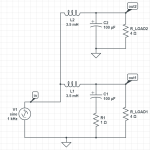
Assume we have two speaker series, Mk1 and Mk2. The woofer low-pass filters on these two speakers are identical; the only difference is the presence of a 1 Ohm resistor connected to the 100uF capacitor. The circuits are depicted below. Mk1 components are labeled "1" in their names, as are Mk2 components.

lowpasscircuits.png

Let us now simulate the results in frequency domain to see the frequency and phase response of these crossovers. The results are shown below.

Frequency plots:
freqplots.png

Phase plots:
phaseplots.png

As can be seen, the frequency curves are nearly synchronized, which is used for the woofers below 400Hz--the crossover point for these woofers assumes they are 3-way designs. So do the phase curves.

My question is, what is the point of installing the 1 Ohm resistor in the Mk1 speaker when the effect, phase adjustment, occurs outside of the woofer's operating range?

Help needed with Voigt speakers build with - Dayton Audio PS220-8 8" Point Source Full-Range Neo Driver

Hi All,

I am looking to build something like this but with a different driver altogether.

Dayton Audio PS220-8 8" Point Source Full-Range Neo Driver, recently sourced and waiting to get them this weekend. I am a newbie and need help in the dimensions and the build.
I could nto find any calculator for this kind of enclosure, any pointers will be helpful or even any dimensions for the build will be greatly appreciated.

Login to view embedded media
Thanks,
GYASK

GK 800RB Capacitor Values

Hello all,

Does anyone happen to know the factory value for the filter capacitors on the +-85v side of a GK 800RB (1992 vintage) power supply section? The ones installed are not original, and I'd like to get things back to their original state. I was given the amp non-functioning by a friend who was going to toss it, and I'm taking it on as a fun project. Thanks in advance for any assistance you can provide.

Chinese TPA3251 amp upgrade

So, I have bought a cheap chinese amp XY-S350H with TPA3251D2.

My question is which parts I should upgrade in this amp to make it sound better? (I can solder SMD parts too)
I'm pretty sure I should change this cheap capacitors, but can't decide which I should use and what else I can upgrade.

There is some detailed photos so you can check it:
Login to view embedded media
undefined - Imgur (9).jpg
undefined - Imgur (8).jpg
undefined - Imgur (1).jpg
undefined - Imgur (6).jpg

Fostex FF165WK Measurements

blogger-image--503034794_480x480.jpg


In this post I test the Fostex FF165WK 6.5" full range driver.

I purchased these drivers ten years ago for a project which was featured on my blog here.

2013 Blog Post 1

2013 Blog Post 2

2013 Blog Post 3

2013 Blog Post 4

2013 Blog Post 5

2013 Blog Post 6

2013 Blog Post 7

2013 Blog Post 8

2013 Blog Post 9

Testing again after ten years.

I was curious to see how these drivers would measure with my ARTA measurement software considering the vast database I've developed in the past five years. Being able to compare the FF165WK data against, for example, the Markaudio CHR120 was something I was personally interested in, considering how much time and effort I spent ten years ago on this driver. I must admit also that I have a bit of nostalgia for this particular driver, among man other single full range drivers.

Contour Network

Over the years I've improved in my ability to develop excellent passive circuits to help achieve the desired frequency response from various drivers. Examples of this is here and here. So I wanted to see if I could use my latest skill to further refine this driver for even more sound quality. Now, I must confess, that this driver is not necessarily anything stand out in terms of sound quality. It is pretty average if I am honest. But I feel like many enthusiasts have similar drivers where they've been tolerating the faults while enjoying what they get right, which is coherency and soundstage depth. In most cases, these faults can large be mitigated through careful contouring of the frequency response with a passive network. (see more later in this blog)

New Tapered Transmission Line Enclosure

In this blog post I also introduce a new tapered transmission line floorstanding enclosure for the FF165WK as a plan set that can be purchased downloaded on my site. This is also an area where I've improved in my ability over the past ten years. I believe the new TL enclosure maximizes the potential bass performance from this driver. Please contact me if you would like a custom enclosure designed for a specific driver.

Super Tweeter

Over the past six months I've been spending a lot time on super tweeters. The FF165WK lends itself to the addition of a super tweeter by virtue of it's natural roll-off above 10kHz. The driver can be used alone, or with a high frequency driver using a range of crossover points ranging from 2kHz - 10kHz. In the context of the DIY enthusiast, the FF165WK can serve has a good test box to evaluate various high frequency solutions. Considering that the overall cost of the FF165WK driver is relatively affordable, the enthusiast just may have money left over for a super tweeter as well.

Appearance

For me I really like the appearance of the FF165WK with it's various shades of grey. It has a vintage look to it as well which some people really like.

General Features of the FF165WK

The particular model stands out from the rest in that it uses a aluminum dust cap to extend the high frequencies as apposed to a whizzer cone. It's part of a family of FF series driver models which range in size from 3", 4", 6.50", and 8.00".

Features

  • Double layer cone
    • Pulp base layer with Kenaf top layer
      • Kenaf layer provides high speed sound propagation
  • Aluminum dust cap
    • Proprietary center dust cap ridge to distribute modal breakup
  • Low loss urethan foam surround
  • Relatively high sensitivity of 92dB/1w for a 6.50" woofer
Measurements

I measured the response at 1m mounted in a 20cm wide transmission line floorstanding speaker. I gated the measurement above 300Hz and then conducted a near field ungated measurement below 300Hz and spliced the two responses.

The on-axis frequency response can be summarized as follows.

  • Very high sensitivity through the midrange (95dB 1w)
  • +5dB rising response from 300Hz - 8kHz
  • -12dB/octave falling response above 8kHz
  • Surround resonance at 4.5kHz
  • Sharp +15dB resonance at 18.5kHz (outside audible band)
Fostex_FF165WK_1m_480x480.png


Comparison for Context

Below is the frequency response of the Markaudio CHR120 for comparison.

Markaudio_CHR120_480x480.png


If I overlay the Fostex FF165WK (Blue) for comparison we can see that the Fostex has significantly higher sensitivity. This is very important if using a low power amplifier since the amplifier is going to produce much less distortion at the lower output voltage. In this particular case the Markaudio will draw two times the power from the amplifier for the same output SPL. When looking at specific low power amps such as the Nelsen Pass Amp Camp Mini, this can be a distortion difference of 39dB in noise floor when comparing distortion between 1v output from the amplifier versus 4.00V (2w).

Markaudio_CHR120_Red_against_Fostex_FF165WK_480x480.png


Off-Axis


Below is the off-axis frequency response overlay for 0, 15, 30 and 45 degrees off-axis. The driver's directivity starts to narrow at around 5kHz. This can be observed by the blue line (30 degree off-axis) at the 5kHz region where things start to fall off as you move up in the frequency spectrum.

Fostex_FF165WK_0_15_30_45_Degrees_Off-Axis_480x480.png


Time Domain

Below is the burst decay out to 20kHz. The resonance at 4.5kHz is likely more audible due to the peak in the frequency response more than it's tail out to 12 periods. So if the peak is subjectively offensive then simply notching out this region is likely a good solution. The peak at 18.5kHz is entertaining to see.

Fostex_FF165WK_1m_20kHz_480x480.png


Extending the burst decay out to 50kHz highlights this resonance even further. We see full ring out to 24 periods. That's a big resonance! Luckily this is outside the audible band.

Fostex_FF165WK_1m_50kHz_BD_480x480.png


The CSD is surprisingly clean with the exception of the 4.5kHz surround resonance.

Fostex_FF165WK_1m_CSD_480x480.png


Correction Network

Based on the above test data it appears the driver performs well with the exception of the following...

  • Midrange peak at 1.5kHz
  • Resonant peak at 5kHz
The below schematic is what I came up with the correct for the above issues. It is comprised of two series LCR contour circuits.

2286-schematic_blanked_out_480x480.png


Below is an overlay between the raw response (red) and the affect of the filter (green).

Fostex_FF165WK_with_Correction_Network_No.2286_480x480.png


I then re-measured the off-axis at 0,15, and 30 degrees off-axis.

Fostex_FF165WK_with_Correction_Network_No.2286_Off_Axis_0_15_30_480x480.png


Below is the time domain performance with the correction network in place.

Fostex_FF165WK_with_Correction_Network_No.2286_BD_480x480.png
Fostex_FF165WK_with_Correction_Network_No.2286_CSD_480x480.png


Bass Cabinet No.2286 -- Tapered Quarter Wave Transmission Line (TQWL)


Untitled_Project_4_b3593228-9b8f-44a1-ab20-e9c365db3cba_480x480.jpg


Below is the half space in-room response without the correction network. The speaker was placed about 30cm from the rear wall. No internal damping material was used in the enclosure.
Fostex_FF165WK_Half_Space_Transmission_Line_480x480.png


Untitled_Project_3_3c4c7939-8f12-4fce-9bb2-fb3621ea7e1b_480x480.jpg


Screenshot2023-11-09115833_d419c455-c4c9-4b75-9d3d-36df6d487c05_480x480.png
Screenshot_2023-11-09_120906_480x480.png
Screenshot_2023-11-09_120941_480x480.png
Screenshot_2023-11-09_120133_480x480.png
Screenshot_2023-11-09_120111_480x480.png

Missing low bass with ported?

Hey everyone.. I'm working on my 1st set of speakers. They are a set of bookshelves using the RS180-8.

The enclosures are about 12.5L and I put a 5.1cm port that's 18cm long. This should give me a Fb of around 47Hz. Based on WinISD this should result in a F3 or around 47dB.

On the impedance chart, it looks like the box is tuned to around 47Hz (assuming I'm reading it right), so that seems right. But when I do a near field measurement of the woofer on axis, the F3 seems more like 76Hz.

When I listen to music, it sounds like it has lots of bass, so I'm trying to understand if this is a measurement issue, or a real issue. If it's a real issue, what causes the early rolloff like that? Should I try to adjust the port to compensate?

Thanks.

Attachments

  • Screenshot 2023-11-14 at 12.05.02 PM.png
    Screenshot 2023-11-14 at 12.05.02 PM.png
    96.6 KB · Views: 115
  • Screenshot 2023-11-14 at 12.08.33 PM.png
    Screenshot 2023-11-14 at 12.08.33 PM.png
    35.9 KB · Views: 114

Seeburg PA4-L6 Schematic Needed--Broke Tube Socket Had to Replace!

Was recapping a Seeburg PA4-L6 when a pin broke off the 12BH7 socket. I am in the process of replacing the socket, however, the photos I took of the assembly before I started don't show where a couple of the capacitors connected to the socket, so I need to refer to the schematic.

It's a narrow, deep chassis with a lot of components crammed in there, and the stuff I needed to replace was in the bottom layer. I was struggling to disconnect a component from the socket when the pin broke. &^%$&^%$!

Just need the details of what hooks to the 12BH7 socket so I can put this back together.

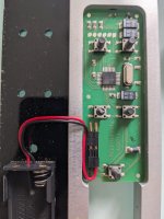
Need Help on Amplifier Remote Tactile Switch

Hello,

My amplifier remote has gone bad. The volume + and - buttons are no longer tactile and it does not come up once pushed. I am planning to replace them and found exact same size tactile switch on Mouser.

https://au.mouser.com/ProductDetail/710-430182095816

My questions are;

1) Is the switch pretty much universal so can use this 12vDC switch as long as it fits in size or I need to somehow find out exact spec to replace with?
The remote takes 2 x 1.5v AAA batteries.

2) Is there specific orientation of the tactile switch that needs to be mounted (such as pin 1 is top left etc) or can be mounted either side as long as two lefts are facing side ways?

Sorry for novice questions and first time replacing tactile switch on remote and any help would be hugely appreciated.

Thank you.

Attachments

  • Remote Tactile Switch.jpg
    Remote Tactile Switch.jpg
    446.5 KB · Views: 98

Orchard Audio Showroom Open House - Nov 19, 2023 - Rockaway, NJ

Join us at the Orchard Audio Open House and experience the future of audio, where every note and sound is brought to life with precision and passion!

📆
Date: November 19th
🕒
Time: Noon - 4pm
📍
Location: 176 Franklin Ave, Rockaway, NJ 07866

What to expect:
🎵
Live demonstrations of our state-of-the-art audio technology.
🔊
Expert insights and Q&A sessions with our team.
🎉
Refreshments and networking with fellow audio enthusiasts.
🎁
Special promotions

Come and celebrate the beauty of sound with us! This open house is the perfect opportunity to get up close and personal with the latest innovations in audio.
Please RSVP at this link to ensure we can accommodate all guests.

Current Setup:
Source: PecanPi+ Streamer – $800
Amplifier: Starkrimson Stereo Ultra – $2650
Speakers: Soundfield Audio M1V2 – $2300 / pair
Cables: Triode Wire Labs
Room Treatment: GIK Acoustics

For more information please contact me here:
orchardaudio.com/contact or 504-233-3444

20231001_164859.jpg

For Sale Europe : PSU PCB for Technics SL-1200 DC Power Supply

Hello everyone, from my Technics SL-1200 DC Power Supply project, I ordered the minimal quantity of 5 PCBs. One sold, I'm left with 3 pieces. Size 110x62mm, details and more pictures on my post in the original thread. Credits to 6L6 for the original design. I deliver the schematics with the PCB, no BOM, but it's easy, super-standard components and spacing, large space for soldering, wide tracks, room for 4 M3 screws at the edges.

Price delivered in continental Europe 13€.
PXL_20231112_132507839.jpg

For Sale Twisted pear Buffalo III multichannel set and miniDSP 2x4HD

Looking to sell the following items.

1) Twisted Pear Audio Buffalo III (ES9018) multichannel set.

Consisting of the following parts:


  • Buffalo III (ES9018) multichannel DAC board;
  • Trident Regulator set;
  • volume control;
  • IVY III linestage (assembled);
  • Placid HD-BP power supply;
  • LCDPS (assembled);
  • Toroidy 9V and 15V transformers;
  • 4 Channel S/PDIF 4 module;
  • Toslink optical input module;
Will also include Mercury IV stage which I got from another member here. It has flying leads attached, but those can be unsoldered.
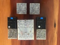
Looking for 500AUD 450AUD (~290USD/270EUR) SOLD.

PXL_20230822_090329754.jpg
PXL_20230822_090145468.jpg
PXL_20230822_090237611.jpg
PXL_20230822_090301762.jpg
PXL_20230822_090210836.jpg
PXL_20230822_090438832.jpg

2) miniDSP 2x4HD

Comes with the power adapter, USB cable and remote.
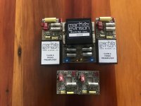
Looking for 275AUD 250AUD (~160USD/150EUR).
PXL_20230822_084431510.jpg
PXL_20230822_084720919.jpg

  • Locked
Gerber File Revisions Needed

In the Pass HPA-1 thread "What Do We Know", a rar file for a clone board was attached in post #508 by @mokaonli. I have been trying to reach him by pm with no success. Is there someone who would be willing to make some small revisions to the Gerber file and also create a drill file? It is Jeff Young’s board but without the logic control, relays, and 5V power supply. I would be most happy to compensate in some way and I would so appreciate it. I am an old retired guy and don’t have the comprehensive skills to learn KiCad or similar. JLCPCB can make the board but they don't seem to understand the simple revisions needed and producing a drill file. I contacted PCBWay, but they want $450 to do some simple changes! But I do not know how much work is involved in a drill file so I may just have Jeff's board made.

https://www.diyaudio.com/community/threads/pass-hpa-1-what-do-we-know.300060/page-26

Soekris R2R DAC Project

Greetings,

Just thought I'd post my DIY DAC based on the DAM 1021 board from Soekris. While I have built several kits before (amps, preamps, phono stages, etc), this was my first attempt at something where I had to source my own components.

For the power suppy, I used a kit from Sparkos labs and paired it with their discrete voltage regulators. While some folks might call "snakeoil" on the idea of using expensive voltage regulators, I have had the privillege of owning two identical DACs in which one was using the Sparkos regulars and one with the stock regulators and I can say with confidence that they do make a noticable difference. As this was going to be a DAC for my main system, I wanted to use the nicest power supply I could afford since the PS was probably going to be the most important component (save for the DAC itself) in this project. The chasis was just a generic DAC chasis from Aliexpress and the TOS board came from DIYTHINK.

At first, I tried using the raw outputs from the DAC because I wanted to avoid using op-amps for output. While the sound was nicely transparent, it was lacking in energy and dynamics. I then switched to the buffered outputs and was much happier with the sound. That being said, I was still not entirelly satisfied. I looked into any other kind of buffer I could use, but was limited by space and my own knowledge. Then I reached out to the folks at Sowter and asked about using a transformer on the raw DAC outputs to get the output I wanted (2v or better). They suggested their 1461 transformer which, according to their calculations, would give me about 2.14v coming from 1.4v/625 ohms into a 10k load (the volume pot on my amp). I wired them in a noticed an immediate difference in the transparency and overall realism of the sound over the buffered (op-amp driven) outputs. It did seem to have a bit less drive/energy over the buffered outputs, but I was still much happier with the sound.

I'm not sure using that transformers to drive the output of a DAC would work for everyone in every circumstance, but they proved to be perfect for me. Hope this helps someone else!


PXL_20231007_203831054.jpg
  • Like
Reactions: manniraj

Difference in ohms

Hi guys, hope all are doing well

Recently I visited a speaker repair site for replacing my woofer cone and spider he said coil was good so he kept the same one

The woofer was 6ohms
Now comming home if I measure it, the meter shows 5ohms
Is this ok or will cause some big issue this decrease ohms will effect only one channel of amplifier and other channel speaker was not repaired just one channel speaker

What do you guys suggest

Thanks
Projects by fanatics, for fanatics
Get answers and advice for everyone wanting to learn the art of audio.
Join the Community
508,468
Members
7,920,968
Messages

Filter

Forum Statistics

Threads
407,835
Messages
7,920,968
Members
508,468
Latest member
Wheelman