Small class A poweramp with current driven outputs

Hi everyone.

For a long time I've been looking for a small class A amplifier around 15 watts to be used as a good known reference when trying out new stuff.
I thought of the good old JLH1969 or a Hiraga. I know both quite well.

But I thought why not try to make my own, which is why I post this thread. I have'nt build it yet, as I have some questions that I hope some of you can help with.
So for now everything is only in LTSpice. I also have to mention that I am not an engineer. I am just curious about audio stuff, and I've learned a lot from this forum.
I have repaired countless amplifiers over time, but designing one is a totally different beast.

So here we go...
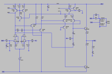
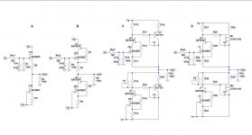
Most of this amplifier is quite basic, except for the output stage, which is inspired by JLH.
It is a quasicomplementary bjt design and the outputs are fed from the vas directly. There are no drivers, no emitter resistors, and no biasing circuitry.

The idea is to try feed the bases of the outputs with a constant current. In this case around 10mA. (Based on the KSC5200 spice model's Hfe).
This is done in the vas stage, which is a differential amplifier running at 20mA, sharing half of that to each output device.
I wanted to see what happens when we apply a signal, thereby changing the current balance, which results in a signal on the output.

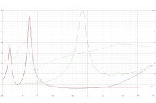
The amplifier has fairly good data, except for the output impedance, which is very high.
Square waves looks reasonable, distortion is low as long as we stay in class a.

Here are some data. I did these sims twice, once without load, and once with load. The test sims are done with the output coil in place between the amp and the load.
The output signal is taken directly on the amp before the coil/load.

NO Load:
OLG 1KHz ~ 80dB
OLG GAIN 20KHz ~ 69dB
UGLF ~ 2.285MHz
PHASE MARGIN ~ 68.3°
GAIN MARGIN ~ 14.7dB

8 Ohm Load:
OLG 1KHz ~ 67.6dB
OLG GAIN 20KHZ ~ 64dB
UGLF ~ 2.228MHz
PHASE MARGIN ~ 68.5°
GAIN MARGIN ~ 15dB

Slewrate is around 22 ~ 23 volt/uS with 8 ohms load and a 1n cap.

Output impedance is 24 ohms up to about 1KHz and starts to rise from there !

8W in 8R+100n @ 20KHz -> Total Harmonic Distortion: 0.001033%(0.001027%)
8W in 8R+100n @ 10KHz -> Total Harmonic Distortion: 0.000536%(0.000524%)
8W in 8R+100n @ 1KHz -> Total Harmonic Distortion: 0.000110%(0.000000%)

Idle current ~ 1.5 to 1.6 amps. Each output device will dissipate 36-40 watts at ±24V

I am trying to figure out if this will actually work with such high output impedance, since high output impedance usually means the damping factor is somewhere between very low to non existant. A speakers impedance isn't linear. It's a reactive load. So probably this amplifier can't sink current from the speaker. Anyway..

The amplifier OLG drops almost 14dB with a load connected. Probably because we have no drivers, and the vas sees the speaker impedance times output Hfe.

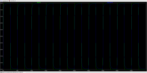
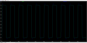
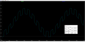
The square waves are all done without input filter at 2V out with 100nS rise/falltime . I think it does'nt look too bad.
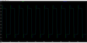
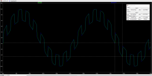
The step responses are at 2V and 8V 20Khz with a 200KHz square wave on top. Rise/falltime is again 100nS.

I am aware that Hfe of the outputs might rise with increased heat. I will test that in reality later on, and implement temperature control if needed.
I am also aware that the UGLF is quite high, but it doesnt seem to cause any problems. Please correct me if I am wrong.
The cascode on the input fets will probably get dropped. It does'nt seem to do much difference in this design.

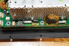
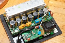
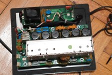
Here are some pictures, and offcause the .asc file for LTSpice.

Let me know what you think, if this is viable, or it should go directly into the trashbin.

I am also interested in other designs that work like this, if you know of any.

Merry Christmas

Attachments

  • Schematic.png
    Schematic.png
    8.7 KB · Views: 163
  • Square wave 2V 8R 0.1uF.png
    Square wave 2V 8R 0.1uF.png
    14.4 KB · Views: 152
  • Square wave 2V 8R 1.0uF.png
    Square wave 2V 8R 1.0uF.png
    14.5 KB · Views: 87
  • Square wave 2V 8R 2.0uF.png
    Square wave 2V 8R 2.0uF.png
    14 KB · Views: 84
  • CurrentAmp 03.asc
    CurrentAmp 03.asc
    30.6 KB · Views: 99
  • Step response 2V 20Khz + 200Khz.png
    Step response 2V 20Khz + 200Khz.png
    23.6 KB · Views: 88
  • Step response 8V 20Khz + 200Khz.png
    Step response 8V 20Khz + 200Khz.png
    24.3 KB · Views: 153

Preamp-Buffers - simple idea

Hi,

just some ideas about discrete Buffers for Line-Level.
I was a bit surprised that I couldn´t find some of these Buffers here at DIYaudio, so I thought I´d give it a try.

Starting with ´A´ the well known and very simple CCS-loaded Source-follower. This can give already good distortion figures and a Buffer can´t be much simpler than that. If J1a and J1b are matched -matched Duals here- one can omit with output coupling caps if the input signal is free of DC.
Beeing a singleended circuit the maximum current into the load could only be once the bias current. This means that it can only drive highimpedance/lowcurrent loads well and heat losses in the JFETs are high.
With smallsignal high-gm JFETs also the supply voltages are usually restricted to less than +-15V.
´B´ is a cascoded variant of ´A´. Here J2a and J2b run much cooler, since the cascode JFETs J3 and J4 provide for low and nearly constant Drain-Source voltages. J3 and J4 may be high Idss low-gm types, which take over most of the heat losses. While the load drive capability is nearly the same as with circuit ´A´, the distortion figures are considerably lower. If J2a and J2b are closely matched, the output offset will remain low enough that no output cap is required, even with unmatched cascode JFETs.

Circuits ´C´ and ´D´ are an idea -I haven´t seen it here before, but very probabely it´s nothing new at all- to increase load drive capability.
It resembles characteristics of a Sziklay- or Compound pair and cascodes.
Circuit ´C´ could probabely named HCC, Hybrid-Cascode-Compound, circuit ´D´ could be called FCC, FET-Cascode-Compound.
Both only differ structurally by the useage of PNP resp. PMOS as output devices.
The voltage drop over the cascodes drain resistors are used to bias and modulate the output transistors.
The two circuits allow to drive much lower impedance loads than ´A´ and ´B´, due to the much increased bias currents (10x and more).
The extreme short and direct feedback loop of the Sziklay pair preserves the good THD-values of the cascoded JFET stage. Since the JFETs may run on smaller bias currents (more degenerated with larger source resistor values) and drain voltages, they run alot cooler. Temperature and temperature drift issues are lower. The Potis in the CCS-JFETs drain allows to tune the output offset, so that no coupling cap should be required. Tolerances of the PMOS might be checked though.
Headroom is lower than with the simpler circuits ´A´ and ´B´, especially with the PMOS output devices of ´D´. With +-15V supplies ´D´ is capable of 4Vrms which is more than sufficient for typical high-level applications.
´D´ shows slightly better THD than ´C´ with highimpedance loads, while ´C´is slightly better with lowimpedance loads and can drive up to 6Vrms.
Using the simmed devices (all in SMD) one could use the same layout for ´C´ and ´D´ for easy evaluation and comparison.
Does anybody recognize some hidden drawbacks apart from possible need of matching the PMOS?

jauu
Calvin

Attachments

  • Preamp-Buffers.jpg
    Preamp-Buffers.jpg
    49.3 KB · Views: 8,959

Substitute for miniDSP Nanosharc

I have for some years been using the DIY edition of the Minidsp 2x4HD without DAC's, named Nanosharc. I have sent the I2S output to two Soekris 1021. Their solution has worked really well for me, the software is easy to work with, and it worked well with the two inputs.
After a firmware update, the unit sends no sound, neither from the Toslink or USB input. I am in contact with Minidsp, but they are slow, and although I still hope for a helpful feedback, I hate being dependent on them for my lovely sound system to work. What else can I do to keep the two Soekris DAC's? I am looking for a kind of DSP solution where I can send two I2S signals after crossover and other DSP processing.
Any advice will be helpful.

Advantages of DCR Dual chamber bass reflex

Looking at this 2 cabinets for Mark Audio CHN 110 I am in doubt:

They seem to have more or less the same volume, and what is the advantage over the DCR Dual chamber bass reflex cabinet over the normal bass reflex?


Updated: I found the Double Chamber Reflex (DCR) article on Electronics World by G.L. Augspurger / December 1961 and attach bellow too for who may be interested.

Attachments

Mini Amp (5 or 10 W) with balanced input for a speaker ?

Hello Guys,

I own an old Realistic SP-150 speaker (2W @ 8 Ohms). It's the same model that was used in the Nasa Control Room for Apollo mission communications.
What I would like is:
- transform this passive speaker to an active speaker with a small mono amplifier and WITH a balanced XLR Input.

I tried to find some electronics boards, but I can't find a small board (or drawing) with a small amp, ideally 12V input or less and this famous balanced XLR input. I don't want an over powerful amplifier like 60W or more. Just the right one for this speaker.
Do you have any idea where or how I can find it ?
I can do PCB and soldering or buy a fully finished product.

Best regards,
Marc

Unexpectedly good EL84 amp

I had been endlessly trying to get a scrapheap amp back working and sounding somewhat good, but just could not get her working. See the thread over here.


Anyway, in the end I just gave up and in an effort to salvage something, anything, I hit upon this schematic, courtesy of tubecad:

An externally hosted image should be here but it was not working when we last tested it.


The thing is, this one sounds absolutely fantastic. Nothing special on any of the parts, all are stuff I had lying around, although I think my transformers are sowters. Anyway, after sorting a few issues with hum etc (thanks again trobbins), this amp is sounding just great. Its easily on a par with the F5s that I've built, and having compared with other amps I've heard, it stands up very well. Soundstage is wide and deep, treble is sparkly and clear with no harshness, bass is tight - although I have heard it in bigger quantities. It really is well worth a mention here as a nice amp to build, lowish to medium gain, and about 8W so good enough for horns.

Its simple enough to build with a low enough parts count. From the tubecad site:

EL84/6BQ5 Push-Pull Power Amplifier
Few tube amplifiers sound as sweet as two triode-connected EL84s in push-pull. These amazing little power tubes are quite efficient, requiring only 15Vpp to bring them to full output. Thus, with just a single input/phase-splitter tube, such as a 6N1P or 12AT7, we build a fine push-pull amplifier.The 6N1P is a fine little tube and about 1Vpk of input signal will bring this amplifier to full output (about 8W) and no feedback loop is employed. The input stage and split-load phase splitter define a CCDA and present an equal amount of B+ noise to the output tubes' grids, which will help reduce the noise at the output. (By the way, the 0.47µF coupling capacitors could be replaced with something smaller, say 0.1µF.) I would use old Dynaco ST35 (also SCA-35) output transformers (about 8k P-to-P), which are stellar performers.


Fran

EMS LB8Mk2 box design

Hello,
I recently purchased new FR speakers from a small french manufacturer called E.M.S. .
They make multiple professional FR speakers that are supposed to be really really good...and as I heard the biggest one (lb12) playing the stars from the sky in a high end setup (https://www.closeracoustics.com/loudspeakers/vigo ) , I jumped in and ordered the same woofers.

Now i would like to test them in an existing diy design that comes close enough to suit their T/S parameters...
could anyone help me identifying what design could be best suited ? Joan, Victors, Vulcans, pencils???, preferably back loaded horn design but not mandatory...
Here are their T/S parameters, I have 2 sizes the lb8mk2 and LB12 mk2

http://www.emspeaker.com/fiche_LB12MKII.pdf

http://www.emspeaker.com/fiche_LB8MKII.pdf

Thank you for the help...
Yves
  • Like
Reactions: LeifB60

Hypnic Power Manager for Raspberry Pi (and other SBCs)

The Hypnic Power Manager
973VivV.jpg


Features
  • Switch power on/off to SBC
  • Provide power switch for SBC
  • Provide power status with LED
  • Remove battery maintenance (use supercapacitors)
  • Provide enough energy to allow the SBC to power down gracefully
  • Optionally, power on SBC when external power is turned on
  • Optionally, power on SBC only where there's enough charge

The Hypnic Power Manager does all of this in a tiny footprint. It's designed to be used with any 5V external power supply of your own choice - a simple wall wort or even an AliExpress special will do, it's not fussy - as long as it's 5V.

When the power button is pressed, or after the external power supply is removed, the board uses supercapacitors to power the SBC - this power supply will last approximately 30s depending on power draw from the SBC. However, the Hypnic sends a "shutdown" signal to the SBC by pulling a pin low on the SBC. A script on the SBC detects the pin state change and shuts down the SBC. Once the graceful power down is complete, a script to pull a pin on the SBC high pulls a pin high on the Hypnic and it removes the power supply to the SBC.

It's powered by an ATTiny24/44/84 and the code is written in Arduino (as that's easier for most DIYers) / Python for the SBC elements - all code is open source, so you can modify and reflash the controller, although you will need an ICSP programmer. The schematic, PCB layout and code are all completely open source.

Why isn't this a Pi HAT?
Screw terminals for all connections to the SBC - this is an intentional choice to make it work with all SBCs - not all SBCs have the same layout as the Raspberry Pi - if this was "Raspberry Pi shaped" (i.e., a HAT) it will only really work with the Pi. Sure, you'll need to hook it up with a few wires, but now it'll work with any SBC and you don't have to mount it on top.

Why did you make this?
While building a new digital audio player based on a Raspberry Pi (a story for another day) I wanted to turn the Raspberry Pi into an "appliance". Like most Single Board Computers (SBCs), the Raspberry Pi by itself doesn't (really) feature a power button without abusing the GPIO. On top of that, you can't simply remove power from it in since it's very possible that you'll either suffer data loss or, worse, corruption. I needed a way to gracefully power down when power is removed. I couldn't find a solution to this off the shelf that wasn't a battery-based UPS. This doesn't work for my application since I'm not trying to keep the Pi running, I want to power it off!

To be clear, yes, I know you can short GPIO pins to power on the Pi, and you can use scripts to with GPIO pins to power it off again. I also know there are UI options - but they're not always practical. And none of these protect against power loss and brownouts, which is something else I need to do.

There are many "UPS" solutions, but they're intended to keep the device on for as long as possible and most don't have a nice way of powering it back on again and virtually none support a power button. On top, they all require batteries and battery maintenance, which is a pain. The answer, of course, is to build it yourself. Enter the Hypnic Power Manager.

Hypnic?
In case you're wondering about the name, a Hypnic Jerk is that sudden movement you get just before you go to sleep... I thought that was apt for a device designed to provide enough power to let the SBC "sleep" and power it down!

PVryRP7.jpg

1GAmucO.jpg

4tknKki.jpg

RVWs2sj.jpg


More Information / Documentation
falk/hypnic at main * gilphilbert/falk * GitHub

Code for the ATTiny
GitHub - gilphilbert/hypnic
This is ready to be opened in VSCode

OK, OK, I want one!
The Hypnic Power Manager is $20 including P+P to mainland USA. Shipping to elsewhere will add some shipping cost. Just PM me with your order!

purpose of voltage divider resistors and caps on WM8805 TX0 output

I am looking for using the wm8805 for simple i2s to spdif converter board and have checked the wm8805 datasheet and some schematics from other implementations. In some diy implementations I found from the internet the TX0 is put directly to toslink output jack while in some other implementations there is a voltage divider implemented + 0.1uF cap before the spdif output. Is the voltage divider and cap really needed and what is the purpose of it?

For example this project uses 210 and 110 resistors and 0.1uF cap. https://www.dimdim.gr/diyaudio/spdif-receiver-with-the-wm8805

Mika

Soundstream TC305 / TC306 / TC308 request information

Dear all,
I write from Italy and I have a Soundstream TC306 and TC308.
TC308 is fully working but with Japan frequency. I would like to modify for europen radio frequency
TC306 is with european frequency but with problem on tape. mecanically is fully working, but when I paly the cassette I listen only radio audio.

I'm looking for service manual, but seems impossible to find it.
If anyone have service manual I appreciate a lot if can help me (I can pay it).
Best regards
Luca

Sinclair (Project 60) 1969 Z-30 amplifier and my DIY mods, schematics + Gerbers

Sinclair (Project 60) Z-30 amplifier and my DIY mods

It was in 1969 when Sinclair Project 60 kit appeared on the market in UK and it contained Z-30 amplifier modules, advertised as 25W and 50W peak. It also advertised to be “the world's lowest distortion high fidelity amplifier”

z30_advert.jpg

and the news and kit description had soon, only few months later, appeared in our local hi-fi magazine Hudba a Zvuk.

Sinclair60_HaZ.jpg

Those days I was building my first amplifiers (with Singleton input stage and awkward circuit topology) and I was excited by Sinclair topology! The differential input stage, CCS VAS load, it was something completely new in the DIY world. However, for us behind the iron curtain, an unobtainium. We had the only chance, to learn and to design and build the thing ourselves.
Several years passed and after I finished my university studies I was still an enthusiastic DIYer and I have returned to the idea to build Z-30. So I took an original schematics

Z-30_orig.png

made some small mods like modification to +/- DC power supply (to get rid off the output coupling capacitor) and also changed the transistors, as the originals were not available here. This was probably a good idea, as my power transistors were more robust. And this was the result, in 1980

1980_module.JPG

I have chosen a modular concept, with a motherboard and modules that could have been changed to make different amp configurations. There was an RIAA phono module, linear preamp module, bass/treble equalizer module, two modified Z-30 modules and a power supply. All except for Z-30 were my designs. It took years to realize the project and this was the result in 1987

ZP-1_Z30_open.jpg

The amplifier was working well and had served me till 2001, the year when I returned to DIY hi-fi and realized to build something more advanced. The amp shown suffered from 2 major issues
the heatsinks were too small and continuous available power was thus reduced (similarly as in nowadays miniature TPA3255 amplifiers)
due to absence of Re resistors and poor idle current stabilization the idle current had to be kept very low, in order to prevent thermal runaway and destruction of power transistors. As a result, there was the crossover distortion. The same issues applied to original Sinclair modules.


Sinclair Z-30 rev2014 – my 45th anniversary project

In 2014, I got an idea to wipe dust from the Z-30 project and to make some modifications and make it a reliable amplifier with continuous maximum power capability, thermal stability and optimal bias of the output stage, to get rid off the crossover distortion.

This was running pretty well, with power specified at 50W/4ohm, thermal stabilization of idle current and appropriate heatsink.


Z-30 2019, last mod 50 years after

And this is my last (as for now 🙂 modification from 2019, 50 years after the original Z-30 was issued.

Schematics and PCB - this is the valid project schematics!

Z-30_new_2019_sch.png Z-30_new_2019_brd.png

(Gerber files are attached at the bottom of this post in the z30_new.zip file, as well as the parts list in pdf)

IMG_2853.jpeg


Measurements

THD and THD+N vs. power at 1kHz/4ohm
Stepped THD level Z30-2019 .png
We can see that the amp gives 50W/4ohm

THD+N vs. frequency - pretty flat
Z-30_thdn_frequency_BW45kHz.png

Distortion spectrum
Z-30_new_SINAD.png

New: 20kHz square response
20kHz_square_4R7.JPG


So this is my story of the Sinclair Z-30 amplifier. Even after 55 years, its basic topology is able to give good results. We have not moved much, since 🙂. Have fun with DIY!

Literature

[1] Project 60 Sinclair, Manual
[2] Dale, R.: The Sinclair Story
[3] Self, D.: Audio Power Amplifier Design Handbook, 4th edition, Newnes 2008
[4] Project 60 firmy Sinclair, Hudba a Zvuk, 7/1971

Attachments

Picked up two TB W4 1320 Si cheap - don't want to make a bass reflex, but a TL (Baby Labs?)

Hello all!
My Fane-bass-reflex speakers are finished. Time for the next project 😵

As the title says, I managed to get 2 W4 2130 Si for a bargain and want to build some PC-speakers.
(https://www.tb-speaker.com/uploads/files/37a412234362bf9297d386299feba31a.pdf)

Currently I have 2 large 42L bass-reflex speakers with W8 1772s in them, but I want to sell them as they take up too much space on the desk.

Concerning desktop/bookshelf speakers, I checked out the "Baby Labs", and fell in love with a smaller, more compact transmission line. However the Baby Lab-models all feature different speakers than the ones I have.

Now I have 2 questions:

Should I just pick the Baby Lab-model that has the closest T/S-parameters and go with that?
(I already compared them and the closest matches I found were the Mark Audio Alpair 6.2 or CHN-70)
https://www.markaudio.com/online_shop/archive/alpair-6-2/#link_additional_information_tab https://www.markaudio.com/online_shop/ch/chn-70-paper-pair/#link_additional_information_tab

Or is there any way a newbie like my can model a MLTL for W4's? I have only worked with WinISD so far.
I have studied the Baby-Lab plans a little and I noticed: there are always three internal walls. And they are always spaced a half length from the previous one. So if the first length is 12cm, the other one is 6 and the last one is 3. Also the vent is always equal to the last walls length, so 3cm.
But that's only what

Ideally speaking maybe someone more knowledgeable than me has the time to do a quick calculation or so, but I hesitate to ask :-D

resistors power rating in a crossover - how do you determine the power rating?

as above.

I was looking at crossover and notice the wirewounds 15W that's being used.

I'm wondering if
  1. the current going through the resistor is constant (thus the resistor temp is constant)
  2. OR perhaps the resistor only warms up in certain situations (playing loud music or maybe the resistor only warms up if certain frequencies are played)
Thanks!

Using ALSA loopbacks and pipewire?

I'm very new to all this, but so far have successfully created an ALSA loopback to start at boot-up, and have directed CamillaDSP to capture from it. I get a few 'SetSpeed' debug messages, but otherwise cdsp seems to run happily.

However, I was expecting a loopback virtual device to appear in the desktop's sound settings, i.e. as another option to play to. But I still just see the hardware cards. I'm not sure if this is because my expectations are simply incorrect, or if it is because Debian now uses uses pipewire, or something else. So basically I don't even know how to direct audio into the loopback sink.

Before I spend yet more time trying to find my answers, could anyone possibly help to prod me in the right direction?
Thanks!
Kev

Symmetric regulated power supply LM317/337

Hello I'm trying to build regulated power supply using LM317 and 337.
I'm using pcb rework from komitart schematic and pcb provided below. Only the leds and their resistors, and fuses are not used in my pcb.

1000010336.jpg


Transformer output is 2x22 volts AC, the positive part of power supply with 317 works perfectly, but I can't figure out what's wrong with the negative part.
The output voltage cannot be regulated, stays 28.5 volts all the time and when I try to adjust the trim pot, 220 ohm resistor start smoking and then burns completely, while the LM377 stays cold all the time.

Another LM337 replaced with brand new purchased from trusted store, recheck everything many times, no short circuit between the copper traces, tried three different brands of LM337, OnSemi, ST Microelectronics and Farnell, and still no luck.

Just to mention that there is no error in placing the regulators, is the same as in komitart pcb, facing each other while the heatsinks are from outer sides.

New Member for the USA

Hello everyone, I hail from California. A simple hobbyist turned audio fanatic

Audio electronics are my passion and hope to learn as much as I can from everyone.
Sought out this community when I discovered the magic smoke. I am determined to discover its secrets.

Currently in the process of attempting a amplifier repair, as well as some modifications to my gear.

Just out of curiosity which DAC chip is your favorite? Mine is Burr Brown from Texas Instruments!
Hope to hear from everyone

Newb of Newbs

I'm retiring and want to explore building stuff myself. I currently have a Audible Illusions Modulus 3a preamp driving a PSE Studio 4 power amp. VPI Junior turntable, and old RCA cd player and about 622 vinyl records. Time to up my game without spending a fortune. I will be asking loads of questions and hope I bring something to the table every now and then.

For Sale or trade: Great Plains Audio 416/802

I have the following drivers for sale. I will also consider local trades for B+ transformers, chokes, audio transformers, early triodes.
Great Plains Audio 416-8B 15" woofers, pair in excellent condition. I used them for several years in VOTT's. I planned on making 10'3 BR for them. I just don't think I will get around to it.
Great Plains Audio 8-2-8D 1" compression drivers, pair in excellent condition, original diaphragms.

$2200. for the complete set, shipping included to con US.

located in Ventura county
  • Like
Reactions: manniraj and mr ed

Modified Klipsch Heresy inspired build, now with bass!


[IMG]

About 15 years ago, I pulled a pair of Klipsch H700 Heresy speakers out of the dumpster at a job site I was managing. I wasn't an audiophile; at the time, a pair of Infinity SM125s that I'd bought at the PX on a private's salary, were the nicest things I'd owned. I knew the "Klipsch Heresy" name, but I didn't know much more than that. I hooked them up to my mid-range Marantz AV amp and thought they just sounded ok...
[IMG]

Life got in the way and about 10 years ago, I gave them to a buddy who had a bitchin' stereo and a nice record collection. I got rid of the rest of my hi-fi and ultimately settled on a bose wave radio that I'd also saved from the trashmen. My pal consigned the speakers to his unheated garage and sometime about 2-4 years ago, I got them back and stored them in my unconditioned carriage house next door. Every time I had to move them, I considered putting them back on the curb; they were definitely worse for wear, with a torn woofer and cabinets that looked like they'd been cobbled together out of scrap.

[IMG]

[IMG]

Recently, I was cleaning out my carriage house to make room for some new tools and the urge to toss them came up again, but I stopped myself and thought "what if I restored them?" so I disassembled them and began to bring them back to life.
[IMG]

[IMG]


[IMG]


[IMG]


First, I sanded the cabinets down, then filled the myriad scratches, dings, chips and dents, then sanded them again to 320 grit, and applied sanding sealer and grain filler. I gave them another light sanding, then applied 6 coats of aklyd enamel.
[IMG]


[IMG]


[IMG]


[IMG]


[IMG]

For Sale Iron preamp fully built kit

Got an opportunity to build this SE kit and used for few months. Not sure but maybe too much of iron paired with sissysit so I am preferring to stay with FE22 and HPA clone preamps. So this needs to go to a deserving home as it’s one of a kind preamp that does tick everything for an awesome setup. Sold as is in the pics.

Asking $240 for the board, selector board and transformer + shipping (Flat rate USPS priority). Prefer selling with the US due to the shipping costs, etc.

1703445140419.jpeg
  • Like
Reactions: Prodigy85 and 6L6

Reliability recommended crossover point manufacturer?

Hi,

I'm looking at building a 2 way, it's my first time (only have experience building subwoofers and using rew/minidisp) and I'm going off some very rudimentary 'rules' I found online to find the drivers. I want to build it using 'PA' style woofers and a CD+horn, going for the 'cinema' experience.

As it's my first 'try', will be used in my home gym, I'm looking at some cheap drivers to see if I like it, if I do, I want to build all my speakers (5.1) for my home theatre.

I already bought my compression drivers, 1" BMS 4550 with RCH H100 horns. They have a nice extension and are quite cheap (200 euro for the pair incl horns)

I'm looking for the woofer, but I'm confused on the crossover.

BMS 4550: minimum crossover is 800Hz (seems very low for a 1")
JBL 2240h: maximum crosover is 800Hz (seems high for a 18"). I can get a pair for 250 euro which seems like a steal (I can probably still sell them afterwards if not used or recone to 2245h)
Would put the JBL in 400L tuned to 30Hz 'monster' cabinets, it extends nicely to 30Hz, and even with only 200Watts it gets plenty loud (116db according to winisd)

(one confusing thing on the 2240h, they mention in the documentation the vented version has less extension up high, but why? I always thought a vented cabinet acts like a sealed above the tuning frequency)

Beaming = 13740 / 18 = 763Hz, and I read it's only audible 1 octave about so about 1.5 Khz. So a 24db crossover at 800Hz should work in theory?

in 'theory' this should be fine, though, I read through a lot of threads saying a 18" should never be crossed over higher than 400Hz, preferably below 200Hz, as they start sounding 'muddy'. Also read the lower the Le, the better it is suited for a high crossover. It's a bit confusing, why would JBL put it's maximum crossover so high if it's no good? Also, how much can be resolved using REW and minidsp?

Alternative to the JBL would be a SB Audience 12MW200, it goes down to 50Hz so will need a subwoofer for the lowest notes, but has much less beaming, starts at 1145Hz for a 12".

Thanks!

Diodes max current in power supply

Hi, friends!
I'm designing a split power supply for a class AB amplifier. The transformer produces approximately 16-0-16V, 2.5A. What continuous current should rectifier diodes be rated for? Will 5A be enough or do I need more? Perhaps for a short time when playing low frequencies the current will be greater? How much greater?? Or this short current peaks are not a problem?

Merry Christmas

In a rare perhaps singular, example of seasonal goodwill from me. Here's wishing you all a jolly non-sectarian / ethnic specific holiday. And a Happy New Year.
Thanks to those who gift their expertise for the amusement and pleasure of others and those contributors who make this sub forum one of the better places in our virtual world.

Is CamillaDSP my only solution? Active Xovers: MacOS -> HDMI -> AVR

Hey Folks,
I've got a nice few generations old AVR here that accepts HDMI, a older intel Macbook Pro with HDMI out & a dream.

I'd like to play with making some upcoming projects active or at least just having a fiddle in that space and I was thinking I'm one software implementation away from being able to "test the waters" and make some active xovers + dsp via the 9 channels of amplification onboard the AVR.

Is CamillaDSP the only solution I have for creating crossovers and dsp, assigned to individual surround channels via HDMI out?
Is it a solution to do what I'm thinking at all?
I think I'd need to use PCM mode?
Is there an easy to use graphical UI for camilladsp that allows you to do this?

I'm not sure what terminology I should be searching within the forum to even research this on my own. I'd appreciate any pointers.

Cheers!

3-way tweeter upgrade

I want to upgrade my 3 way active speaker with a better tweeter. Have celestion ftr15 3070c in Onken 360l, fostex 299 compression drivers such as mid, and BMS4538 as tweeters. I'm missing a bit at the top like crunch and details. The BMS is comfortable, but a little too kind.

A compression tweeter would be a good alternative to my JMLC 1000. Active sharing is currently set to 800Hz og 5000Hz.

IMG_20230312_094648.jpg
JMLC-1000c.jpg
  • Like
Reactions: GM

Repairing a Musical Fidelity A1X

Hi, I love looking at descriptions and photos of repairs other people have done.
So I thought to give back to people also enjoying that.

A little while ago, I bought a MF A1X, being in good optical condition, but the owner said it had suddenly stopped working.
He also said the source selector was not working well anymore.

When I had it on the bench, I saw that in the past someone had fiddled with it, and not too expertly.

The power cable had been replaced by one with a ground wire, although it originally was sold with "Schutzklasse 2" (Germany / EU), meaning no ground and internal high voltage being completely isolated.
The ground wire of that "new" cable was just screwed to the painted case. Not sure what the intention behind all that "modification" was.

05.jpg


Power supply capacitors had visibly suffered. Other caps as well, see shrunken isolation on small electrolytic bottom right. I am not sure if these were the original caps or if they had been replaced before.

01.jpg


There were also other creative changes, like this strange wire, which was for fixing a broken PCB track (the PCBs of old MF equipment are real sh*t and tracks come off really easily).

07.jpg


Also not original was this "thing", maybe it was intended as part of some temperature circuit? It was not connected anywhere, though.

02.jpg


The sudden stopping to work was indicating the fuse was blown and it was. Testing after replacing it with a dim bulb tester showed a nice glowing lamp, so there was more.

I got out the board and tested the rectifiers on the PS first and indeed one of them had a short.

06.jpg

F2J JIG using Depletion Mode JFETS.

Hi All!

I'm looking at trying to cobble together an F2J JIG that I can test UnitedSIC JFETS with. I'm not looking for the magical "Triode" like behaviour or any special tones. Just an amplifier of around 5 Watts with a relatively low distortion figure and can drive 88dbw/M speakers 6 OHM. (Paradigm Signature Reference S2) I spoke with Mr. Pass (Papa Pass) and he stated I can just plug them in and tinker and warned me about using depletion mode JFETS (which I have studied in class A self biasing modes) in the f2J, however he chose a rare variety of enhanced mode JFET. I asked my professor about these and he said they don't exist and told me to start designing with common parts! So, I looked into it further and actually they are mostly normally off devices (the common JFET needs a few volts negative to turn it on!) well... yes.. hes correct in that ALL of our tests and labs we are using small signal JFETS which are only depletion mode devices and enhancement mode devices are usually strictly Mosfets and further I learned today that they are now discrete cascode MOS/JFET design. (UJ4C075060K3S) which is actually a JFET/MOSFET in the same package. 🤔

My main idea for this year end project was to demonstrate a small 5w Amp using PAPA F2J to my class but instead of trying to find or buy rare R100 Semisouth devices I wanted to use something common like depletion mode devices from UnitedSiC, biased in CLASS A with liquid cooling; more specifically these SiC depletion devices I found and are easily available to me: UJ3N065080K3S or UJ3N120070K3S

Using his production ready circuit and trying to "plug in" these devices will not work as the original F2J is using rare enhanced mode JFETS with positive bias on the gate, so...

My question what is the most elegant way to develop negative bias to the gate using a simple bench power supply? Obviously, Opening R4 and directing it to a negative voltage regulator source came to mind? Is there anything else I need to change in the F2J layout so that I can save some time and headaches with my project? I am seeking to demonstrate a low noise and low THD CLASS A amplifier with a liquid cooling system.

I hope to learn and build with modern Silicon Carbide or GaN devices so please go easy on me!

Thank you so much.

Jeff

Attachments

  • F2J.jpg
    F2J.jpg
    244.6 KB · Views: 452

Mr. Wondercone & his wife Mrs. Magicdome having a new baby :)

How should we call them? The wondrous magicians?

Now first here is the adopted baby from far east that will make you scratch your head about the plain ugliness :

https://sbacoustics.com/wp-content/uploads/2020/02/75-SATORI-MT19CP-4-GRAFIK.jpg

And Mr. Adopter himself with an answer in the comments : Login to view embedded media
So the answer is : The ROOM is healing everything! (any deficite)

Gosh! Never thought speaker development is so easy!

Some guys & girls have all the luck!?

Sony Cinema Space DIY project using LA2615 AViSS 3D Surround Algorithm

Enter the LA2615, an Analog Surround IC featuring the AViSS 3D Surround Algorithm a proprietary technology by SANYO Electric. This ingenious technology, initially commercialized by Sony under the name “Cinema Space” in their hi-fi audio systems, transforms a stereo image into a virtual surround sound, adding a new dimension to the audio experience.
LA2615 - Copy.png

While I stumbled upon a few applications of LA2615 in service manuals of hi-fi systems by Sony and Sanyo, I noticed a gap in DIY projects featuring this IC. Undeterred, I ordered the IC, which arrived in a compact SMD-type package instead of the one I intended. No matter, I decided to take on the challenge and implemented the circuit on a vero board, employing a bit of a hack to solder the IC.
Hack to solder SMD components to a vero board.jpg LA2615 Completed Circuit.jpg

With ample space in my amplifier cabinet, I easily found the place to locate it. I incorporated the surround sound circuit just between the audio input source and the tone-controller unit.
Integration of surround sound unit with the amplifier.jpg

Notable aspects:
  • The IC preserves the original tone of the music, ensuring fidelity.
  • No unwanted reverb effect is added, providing a natural surround sound experience.
  • True surround sound: The direction of the sound is distinctly felt, creating a spacious auditory effect.

Read the full article on Medium: https://medium.com/@rasansmn/enhanc...2615-aviss-3d-surround-algorithm-c3da32d80949

Watch the short video of the full process:
Login to view embedded media
A demo:
Login to view embedded media
Any thoughts or questions? This thread is for you. Thanks.

A manifesto for Audio DIY-ers

A manifesto for Audio DIY-ers


Edward T Dell (†)
Jan Didden

The title for this essay is borrowed from an Editorial that appeared in The Audio Amateur (now AudioXpress) some 30 years ago. It’s Owner, Publisher and Editor was Edward T Dell, a man who singlehandedly did more to promote DIY audio than anyone else I know. He was a great inspiration to me and ultimately responsible for my publishing and writing activities.

If you want to know what kind of man he was, read my interview with him at linearaudio.nl under My interview… I decided that after 30+ years, the Manifesto should be revisited. I have shortened it as well as updated it, in a few places, but tried to keep the same spirit. I am confident Ed wouldn’t mind at all, on the contrary. I thank the good people at AudioXpress, the copyright holders of the original, for allowing use of this material.


Who is this ‘audio diy-er’?


The most poorly maintained piece of equipment around most diyaudio workbenches is the guy who sits in front of it. Most of us ‘hang in there’ with this audio enterprise not because we feel confident of our ability or our knowledge or experience or skill but because we have a lot of hope and guts. And thousands of audio diy-ers have given up along the way somewhere and turned to golf, or bowling, or model railroading. They did so because of a number of reasons which we think must be sorted out if this avocation is to have any future.

The typical audio diy-er is a music lover whose appetite is partly satisfied by reproduced music. The pursuit of lifelike music in any particular place calls for a great variety of skills. Seldom are all of them present in one person. But the development of one or more of those skills is the substance of the audio diy-er’s avocation.

It may be speakers, and speaker construction that captivates those who usually combine a love for woodworking and a strong back.
The kit building diy-er sometimes develops a passion for kits like some people do for crossword puzzles. The kit maven searches for friends for whom he can build, or may even go so far as to set up a mail order kit building service for a price. At least he has found a way for his addiction to pay for itself.

The tinkerer has all the parts for some twenty-three projects gathered together on his basement shelves – all ready to be built – someday. Several other projects – in various stages of completion – also occupy his shelves. But little of his handiwork has found its way to completion or into his audio system – yet.

The modifier likes to customize. He’s built a few kits but is happiest when he’s changing a value here and there to make his equipment ‘his own’.

The general diy-er may have a little or any or all of the preceding types in him. He probably started in kits, has tried a speaker or two, has done some modification of his equipment, maintains it – most of the time – and has several partly finished and more ‘parts collected’ projects ready to do ‘when he gets a little time’.

The audio diy hobby requires a place to work. No matter how small – the table in the corner of a small apartment – or how big, which may be half a cellar full of benches and tools. It is the place the audio diy-er finds his fulfillment. The tools are as various as the wide range of related skills the diy-er must call on to do his work. Some diy-ers limit themselves, by preference or because they live in tiny apartments, to the basic hand tools and do little in the way of metalwork or original construction from scratch. Their test gear maybe limited to a meter, a generator, and a small ‘scope. Currently possibilities abound to design a metal case for your project, or indeed a complete multilayer PCB on your own PC, then ordering it through the ‘net. Nothing more is really needed to turn out projects that cannot be distinguished from what comes off a manufacturers’ assembly line.

Any diy-er will have to invest in test gear, construction tools, and materials. The serious diy-er keeps stocks of resistors, capacitors of a wide variety of vales and types on hand to try out a circuit idea he gets. He probably owns a small library of reference books which he turns to regularly for information.

The moment of truth


Every audio diy-er experiences a moment which sums up our whole reason for being what we are. The project is finished. You have checked it over several times. The terrible last moments of anxiety before turn-on are with you. You make a quick look – to again make sure the clippings are all shaken out, the connections are all secure, the capacitor polarities are all correct, the transistor leads are all properly oriented. That’s it. The loneliness, stillness, and anxiety of those last moments are nearly unbearable.

You flip the switch and one of three things happens: 1. Absolutely nothing; 2. a bright flash and a sickening smell; 3. a quiet hum, a reassuring LED coming on, and a fuse that stays intact. The test signal goes in, the wave pops up on the ‘scope screen.

Out of dread to ecstasy. No flight is faster, no distance further. No feeling is quite like this one. And it is what audio diy is all about. It is the central essence of what this hobby is all about. Our delight and satisfaction is something no one can understand who has not experienced it himself.

We are convinced that home craftsmanship is a vitally necessary development to our quality of life as a people in this post-industrial revolution era. Your pleasure and mine in the systematic exploration of the by-ways of audio with our minds and hands is a pleasure – and a journey we ought to cultivate. But what are the obstacles to that path of endeavor?
Ourselves, mostly.

Our most basic problem as audio diy-ers isn’t knowledge of electronic theory, it is knowledge of ourselves. If, when you turn on that switch and result No. 1 or No. 2 occurs, what you think of your own ability, and the kind of confidence you have in yourself is the most important consideration in the whole matter.

We have developed some suggestions about this game all of us should be playing for keeps.

First: believe that you can do the job. Despite the momentary setback, be sure you are going to come through this eventually. Never give in to the idea you are too uninformed, or stupid, to solve the problem sooner or later. It has an answer and you can find it

Second: do not think the worst. You will be strongly tempted to do so. Don’t panic. Decide ahead of time that things often go wrong. Electronic circuits are by nature, very intolerant of even small mistakes. They need to be nearly perfect to work at all.

Third: be sensible. Don’t work when you are overtired. Leave a problem overnight and come back to it fresh.

Fourth: ninety-nine percent of the problems of construction are simple errors on your part. A later, refreshed look at the problem may show you the error clearly and immediately. Don’t blame the designer. Troubles are very seldom engineering, although published articles do tend to have errors in them and it takes time to catch them. Be wary of projects which show signs of being based on theory or calculations or simulations only. Look for prototypes and some indication that the author has actually built what he describes.

Fifth: Audio Diy-ers, being few, tend to be loners, often out of necessity but sometimes out of lack of effort or because of personal preference. A friend who can go over your work – and whose work you can check – is a highly valuable and effective help with trouble shooting and morale. Even a non-audio type can help by listening as you go through the circuit and explain it to him. You can catch errors by verbalizing what you have done for him – and hearing yourself in the process. Of course, diyaudio is a limitless resource for this type of help.

Sixth: Check out the work systematically, follow a plan that is logical and do it step by step:

  1. 1. Check component values and polarity;
  2. 2. Inspect for cold solder joints;
  3. 3. Check for loose connections and intermittents;
  4. 4. Check your input and output cables;
  5. 5. Measure voltages for peculiarities and follow the clues to their source;
  6. 6. Follow the signal through the unit backwards from output to input for signs of life;
  7. 7. Systematically begin a check of components and substitute where you have doubts about the component;
  8. 8. Stay with it until you find the problem. Don’t ‘put it away’ on a shelf for a later day. It will stagnate and get cold – ending up as junk and mute evidence of your inability to deal with the problem;
  9. 9. Be aggressive. Intelligent caution is to be observed, but don’t let your fear of the beast make you unwilling to try things that will unravel the mystery.

What becomes obvious from the above list is that careful work habits, and high standards of construction practice can save a lot of headaches after turn-on. Unless they are new, check resistors for value, capacitors for value and for leakage or insulation.

Check transformers for continuity and power types for correct voltage (remembering that you are checking peak, unloaded values). Diodes and transistors can be checked for junctions with an ohmmeter – or the latter checked for gain on a tester. Be sure that reverse or blocking reading on the diode junction is high resistance too. That can be as important as the 10-20 ohms reading on the current passing connection.

Clean circuit boards just before assembling them and clean all component leads (except gold or silver flashed ones) by using a pair of diagonal cutters to scrape away the oxide from the tinning material. This speeds the soldering process and insures a good joint, quickly made.

Use a heat sink like X-Acto’s handy reverse tension tweezers on all semiconductor leads. It takes a little more time but is a good precaution against post-construction problems. Systematic, constructive thinking, perhaps out loud – or even on paper – is basic to finding troubles in electronic circuitry.

It is important to remember that a very modest store of theoretical knowledge can carry you a long, long way in this field. This is not to say we don’t all need theory knowledge, it I only to remind ourselves that the lack of such knowledge is no excuse for giving up on trouble shooting a piece of construction. Theory is important to design. Out-and-try experimentation can accomplish some things in design but good results are nearly all luck in such cases. But proper function of audio equipment is possible with modest amounts of information.

The same truth ought to give audio diy-ers without much formal training the needed courage to try projects on their own. That basic lack of confidence, with the feeling that one doesn’t know enough, keeps many diy-ers stuck in the shallow wading pool permanently.
Venturing into scratch building will give you new experiences, give you the chance to gain new knowledge, and send you on a search for new information. All of us are apt to look for new information when we have a pressing, practical reason for doing so. Trouble shooting can provide that reason if we keep our heads - and our courage – and press on to a solution. You will be surprised, as you push your way on through projects, how much information you pick up along the way. The knowledge is cumulative, too. The parts and ideas begin to fit together in a whole structure.

Every rule, of course, has its exceptions. Some of us seem to be born ‘all thumbs’. And for some conditions of that kind a few of us will simply have to accept in ourselves a permanent limitation. But much of that ‘all thumbs’ syndrome, however, seems to me psychological in origin with a basis which is mostly dependent on the opinion of the person about himself. Doubtless some of us are destined to remain onlookers for lack of manual dexterity, but though that limitation may close off original construction, it does not preclude some modification, maintenance and testing, nor all the pleasures of live recording.

This avocation of audio is worth the best efforts we can give it. Its value is far more than the pleasure of listening to superbly reproduced music. It is basically a satisfaction of one innate human appetite to create, to achieve, and to add one more artifact to the world’s collection of wonders. And the best of it all is that you did create that particular wonder yourself.

This forum you are perusing is meant to help every member to become an active, self-conscious, and in many instances articulate, audio diy-er. We ought to spread the word about this hobby among those who most certainly would enjoy its pleasures and satisfactions.

Let those who will, be content with what the merchandiser is willing to market. The audio diy-er is a different breed.

Tangband 5” Tapped tapered QW tube…

Not sure if these are ‘TL’ or tapped pipe? the sims and impedance plots are somewhere in between .

Did the horrible TS parameters and actual driver Fs of 59.4 (instead of 45) gimme that hump In the middle of the babdwidth?

Attachments

  • F1D375D5-19D3-414F-8537-09B9FF3A4418.jpeg
    F1D375D5-19D3-414F-8537-09B9FF3A4418.jpeg
    623.8 KB · Views: 180
  • 019FF6F7-3966-4C1B-B156-7D4B63999AF9.jpeg
    019FF6F7-3966-4C1B-B156-7D4B63999AF9.jpeg
    477.5 KB · Views: 176
  • 91E2936C-18A3-46CD-812D-72418CB26944.jpeg
    91E2936C-18A3-46CD-812D-72418CB26944.jpeg
    454.7 KB · Views: 183
  • A568A0A8-F3E7-4D90-960A-4C3EFE9FB95C.png
    A568A0A8-F3E7-4D90-960A-4C3EFE9FB95C.png
    6.3 KB · Views: 164
  • 5877CFB4-D876-4505-AC7A-1FF7C92CC8DA.png
    5877CFB4-D876-4505-AC7A-1FF7C92CC8DA.png
    14.7 KB · Views: 178

Tang Band W6-2313 - SUG2-25 based project

Hi everyone

A while ago I found on the tang band website the SUG2-25 project based on the Tang Bang w6-2313 full range speaker. I was curious and decided to simulate the crossover given on the tang band website for this project. The thing is the graphs don't look very similar to the one given by tang band on this speaker project. Anybody had the same experience? Since I don't have the speaker I can't make any kind of measurement, but I tried to "fix" the crossover at least. Open to suggestions to improve the circuit!
The speaker is a 17 L box, with a 300x64 mm port. Also if anybody has better suggestions to use this full ranger let me know!

Attachments

  • Screenshot 2023-12-21 185539.png
    Screenshot 2023-12-21 185539.png
    189.2 KB · Views: 287
  • Screenshot 2023-12-21 185624.png
    Screenshot 2023-12-21 185624.png
    55.7 KB · Views: 254
  • Screenshot 2023-12-21 185638.png
    Screenshot 2023-12-21 185638.png
    55.5 KB · Views: 234
  • Like
Reactions: Hondasnl

Velodyne MiniVee sounds quiet and occasional popping sounds

have 2 of these velodyne minivee subwoofers. 8"

one is producing bass but at very low volume levels.

moving volume knob up and down doesn't really help. volume level does not change. I seriously doubt its a dirty volume knob.

there are occasional popping noises. the driver jerks during pops.

visually things look ok. except 2 resistors that look like running hot.

hard to tell from pictures. but if you look close that part of the board is brownish. part where the 2 big blue resistors are and 2 similar smaller resistors.

anyone familiar with velodyne amplifier short cuts / optimizations. anyway to approximate wattage rating of those resistors?

a lot of people put more powerful resistors in velodyne amplifiers.

the large blue resistors are 16mm long and 5mm in diameter

small pair next to each other are 8mm long about 2.5mm in diameter

Attachments

  • DSC00005.JPG
    DSC00005.JPG
    353.1 KB · Views: 156
  • DSC00004.JPG
    DSC00004.JPG
    422.7 KB · Views: 214
  • DSC00003.JPG
    DSC00003.JPG
    346.1 KB · Views: 164
  • DSC00001.JPG
    DSC00001.JPG
    373.6 KB · Views: 164
  • DSC00002.JPG
    DSC00002.JPG
    342.7 KB · Views: 146

Classe DR-8 Input Board Opamp Ugrade

I'm helping a friend out with some upgrades on his pair of Classe DR-8 amps, which he has been using bridged as mono blocks for many years.

The input board of each amp has four opamps, however Classe went out of their way to remove the model numbers of them (see the attached photo).

My Classe CA-300 uses two dual opamps on the input board, so I'm assuming these CA-8's are single opamps. The schematic I was able to find online doesn't show the input board at all, and the service department at B&W (who now support old Classe products since the original Classe design and support teams were lost with company closure) don't have any documentation as to what opamps were used.

Does anyone here have a suggestion what these opamps might be? Based on the age of the amp there are probably better parts to use, but I don't want to mess with anything blind. Thanks in advance.

Attachments

  • Keith DR-8 input board a.jpg
    Keith DR-8 input board a.jpg
    462.3 KB · Views: 277

decision fork: DSP vs passive?

Hi folks!

I’m at a fork in my next 3-way build, and I’m hoping for some feedback. I’ve already chosen drivers that will play very nicely with each other in terms of crossover design and I’m working on my cabinets. While I was mulling things over late last night, I got to thinking… “What if I went with a DSP instead of passive crossovers?” What makes the question hard -- for me -- is that I have a very nice SET tube amp I absolutely love. The amp wasn’t cheap and I’m not in a position to buy 2 more in order to accommodate the additional 4 channels of an active DSP configuration. Right now, my budget for crossover components or DSP (to include DSP and two additional amplifiers) is ~$1000.

This brings me to my immediate question: do the advantages of DSP with cheap DSP/amplifiers outweigh the advantages of a single, very high quality amplifier in a traditional, passive system with very high quality crossover components?

I know there are some strong opinions about passive vs. active/DSP and it isn’t my intention to open that can of worms in the abstract. I’m inquiring specifically for my build constraints and resources, which is the path of greater acoustic efficacy?

If the consensus is “go with good passive crossovers, for what you have now” then that’s easy. If folks think DSP would be better… well, that’s where my knowledge base tapers off. I’ve built a couple DSP/active systems in the past, but they were not what I would consider serious audiophile endeavors (sorry, I know that’s a loaded term): stock GUI/software (e.g. SigmaStudio or miniDSP stock interface) and “decent” class D amps. So... in the case of DSP/active, I have myriad questions (but I’ll start with just a couple):

1. For a high quality build on a limited budget, what DSP? A miniDSP Flex Eight? Or something else?

2. For programming the DSP, should I use the basic GUI/software or tackle more complex FIR stuff? Or start with one and build up to the latter? Oh, and full disclosure, I don’t know squat about building/implementing FIR filters -- but I’m willing to learn!

Thanks in advance for the feedback and for sharing your knowledge. 🙂

Unmarked failed diode in 1990 Volvo/Alpine 4x20w Amplifier

Hi, folks. First post, but I'll try to make this make sense. I have some electronics repair experience but need a bit of help with this.


I've had substantial hum any time the incandescent headlights or ignition are on and static/clipping above a certain volume level especially on one side on a factory amplifier in a 1990 Volvo. Some people claim they were Alpine units. It is listed as a 20w x4 channel amplifier with Volvo part number 353004. The front speakers are 4 ohm and the rear are 8 ohm, which seems interesting.

The board is marked 55 11511-02 front and rear (front says Art No. in front of it). The rear is also marked 94V0 (looks like the board material) and w8939-Le and has 2 symbols. One is an F with ELEC above the center line and 3330B below, and the other is a mirror images LR with the vertical line of the R touching the bottom line of the L.

There is one 14-pin IC marked Portugal 8926BR and TL074IN. Looks like a 4-channel amplifier from TI (https://www.ti.com/product/TL074) but I don't understand the info on that page very well.

I took it apart and snapped some photos. I checked the glass case SMD diodes inside because 2 of 3 glass cases on surface mount diodes are cracked. Two test ok with a diode mode test reading of 538 and 539, but one of those has a cracked case. The third one tests with a value of 1850. None are shorted or open on a 2k-ohm resistance check. I know these aren't really meaningful values, but the big mismatch and very cracked case makes me think this diode could be blown. Then again, these readings have all been done with the parts installed.


Where I need help is I would like to replace these 2 or 3 diodes but I'm not sure what they are. The glass case makes me think Zener diodes. They have no numbers or identifiers on them even with a 20x magnifier loupe. I see only a black stripe on the end and a silver stripe in the center, which I don't see on any diode color code charts. In fact, I've seen several charts that list silver and say N/A. I've looked at some sites like Mouser but am not sure what voltage rating I should be looking for.


I found forum website from the BCAE1 website, and it has several photos of diodes exactly like this in amplifier circuits. Is this some sort of generic noise filter diode or does the info on the OP-AMP page give enough info to pick a voltage limit for replacement parts? Does anyone else have ideas on repairing this? I've tried to keep this car a budget driver while I finish my master's degree, and I'd love to not buy more than a few small components to keep the stereo working. I have another of the same amp like this, but I have little faith in it being in better condition than this one.

The suspect diodes on the back correspond to the front area with C03 T01 and T02 in the top left of the image I posted.

Thanks very much in advance!
William

Attachments

  • IMG_20231207_175521.jpg
    IMG_20231207_175521.jpg
    206.1 KB · Views: 123
  • IMG_20231206_154512895_HDR.jpg
    IMG_20231206_154512895_HDR.jpg
    348.8 KB · Views: 122
  • IMG_20231206_205154267.jpg
    IMG_20231206_205154267.jpg
    371.2 KB · Views: 127

A 6P13S sweep tube amplifier build

I have been working for sometime on a basic push-pull power amplifier using the Russian 6P13S sweep tube and the 6F12P pentode-triode.
Recently I started testing my working proto type so I thought I would post some results in case there is interest.
The 6F12P pentode-triode was selected at the time I started as it has a high transconductance of S=19 allowing high gain and good bandwidth. The triode section although limited in peak current also has the same S=19 allowing it to track closely the pentode signal when used as a split load phase inverter. The result is high gain, low THD and wide bandwidth.
Unfortunately they have become harder to find with a lots now on the market that are used and too low in emissions to be of any use. Pity as it is a good tube and for personal reasons I am unable to buy from russia at this point in history while hoping for better times in the future.
Sweep tubes are interesting beasts as even the smaller sizes like the 6P13S given appropriate screen voltages they can deliver high levels of peak plate current. Often far higher than for example a typical 6L6.
The high peak plate current provides some benefits on musical peaks at both the higher and lower frequencies where higher levels of peak current can be required due to transformer and loudspeaker issues. A lot of tube designs measure great to 1KHz with sine waves into the designed impedance but struggle to produce musical peaks into off impedance loads like a real loudspeaker. At frequency extremes transformer issues can also limit performance due to lack of available peak current from winding capacitance at high frequencies or magnetizing inductance current at low frequencies.
So I though to see what a higher peak current sweep tube design would do designed into a 6L6 class power range of about 30Watts RMS. I did not use the larger sweep tubes as they have become expensive and hard to get but the 6P13S is still low cost. Admittedly it would have been easier to just use the trusty 6L6 but where is the fun in that?
There is reason to believe sweep tubes can be pushed past their rating with some confidence as they were designed to run hot at full power and very high peak voltage and current continually with years long reliability in TV use. Some old application notes suggested 40% over the sweep rating for audio use.
Most sweep tubes will not tolerate the high screen voltages that the 6L6, EL34 or KT88 will making UL operation a bit more challenging. Custom transformers with a separate screen winding is one solution but far too costly for this project. I used a screen connection for the 6P13S UL operation with the AC portion of the screen signal capacitance coupled from the output transformer UL tap and the DC screen current feed from a regulated DC power supply. As the sweep tubes are more sensitive to screen voltage changes I further reduced the UL AC signal level by a two resistor voltage divider and this provided the lowest THD of all versions.
This simulated and worked well on the bench and compared well to straight pentode operation. UL operation seemed at first to provide little advantage over straight pentode operation in distortion or stability until I noted output peaking at 500Khz occurred in the pentode version when the output load impedance was mismatched to the transformer.
This suggested that dynamic stability would likely be improved with the local feedback that UL operation provides in the output stage.

Below is the spice circuit and spice THD test results. Note total THD is highest with 40% UL operation and lowest with the UL AC screen signal reduced by 4. Total power output was a bit lower in 40% UL. Square wave response was unchanged.
All simulated at 30watts output into 8 ohms.
Pentode operation, regulated screen THD=0.1625187 PERCENT
40% UL, regulated screen THD = 0.4871198 PERCENT
40% UL level divided by 4, regulated screen, THD = 0.1262827 PERCENT
With UL screen drive reduced from 40% by a factor of 4 distortion dropped and power levels returned to near pentode levels. This UL version seemed a good compromise in added complexity in exchange for potentially improved stability.
In spice UL 8 ohm frequency response was -0.3dB down at 20Hz and -0.24dB 20KHz and with peaking down -11dB at 1Mhz frequency measured into 8 ohms and at 8,000 ohms load down -4.5dB ohms at 1.3Mhz suggesting stability. Note we are looking at a audio amplifier's frequency and phase response up and into the Mhz. This has nothing to do with reproducing these frequencies but does give clues as the stability of the amplifier. You will note I look down to below .1Hz and well above 1Mhz in the plots. There is much going inside in a audio amplifier that happens far outside frequencies that audio test equipment can measure that is important in how a amplifier will sound when dealing with dynamic transients found in music. Spice makes seeing this easy but a lab setup to measure this on the bench is no easy task.
I created the spice models for the tubes using a Utracer 4+ to collect detailed data on the tubes and then Ronald's modeling software to create the spice models by measuring actual sample NOS tubes. Wonderful tool but there is a learning curve in creating models with this software. Highly recommended and well worth the effort.
Power output in spice was about 30 watts with THD at about 0.126 % and
bench testing showed that was not far off the real world with the proto type producing 26 watts at 0.094% THD at 2KHz and at 1 watt 0.0177% THD. The actually bench voltage rail being a bit lower than I used in spice could be why the power level is down a bit.
20Hz testing produced 26W @ 2%, 10W @ 0.478% and 1 watt @ 0.167%
200Hz at 1W @ was 0.0369%
20KHz produced 26W @ 1.3% and at 1 watt @ 0.198%
Square wave response in spice at 1Khz looked very clean with no ringing or over shoot and nice sharp edges.
Bench testing at 20Hz, 200Hz, 2KHz and 20KHz shows nice sharp clean edges confirming stable wide bandwidth.
The 20Hz square wave apart from the strong tilt due to low frequency loss shows monotonic lines suggesting a absence of saturation, strong non-linearity's or instability in the transformer and feedback loop a this very low frequency.
The 200Hz square wave has clean edges with modest tilt and no ringing or over shoot.
At 2Khz the square wave is very fast and clean with perhaps a tiny over shoot so small it could be a artifact of the scope probe setup (I did not take the time to calibrate the scope probe). 20Khz square waves are starting to show some loss of rise time but again are very well behaved with perhaps a small amount of leading edge over shoot. Considering this 20Khz waveform went through a great big hunk of copper and iron to me this is impressive and suggests the Hammond 1650T transformer used are very well designed and made.
If there is interest I will post more detail of the PCB layout and the actual PCB proto type amplifier circuit diagram as well as the regulated power supplies used for this project.
Bench setup
proto-type-top.jpg
ptoto_type_bottom.jpg
2KHZ_SQUARE_WAVE.jpg
2KHZ-1WATT-THD.jpg
2KHZ-1WATT-THD-SCOPE.jpg
2KHZ-26WATT-THD.jpg
2KHZ-26WATT-THD-SCOPE.jpg
20HZ_SQUARE_WAVE.jpg
20KHZ_SQUARE_WAVE.jpg
200HZ_SQUARE_WAVE.jpg
UL_spice-AC.jpg

Attachments

SE amp output to speaker w/ high pass crossover, and to ‘high level input’ for bass amp

Putting together a new horn & flea power system for my daughter and her husband. One approach I am investigating is using an SE 45 amp, driving:

- a horn speaker setup from about 300hz up, which has a conventional speaker level high-pass crossover.

- a plate amp (likely Hypex) for the bass horn below 300hz, using the plate amp’s ’high level input’.

my concern is: will I have issues with the load that the SE 45 amp sees? Potential distortion of lower frequencies not having a conventional load? Or am I overthinking things?

The speaker level input to a Hypex amp and managing the bass with software is an awfully appealing approach, makes things very simple. At least until the tech changes and the outdated hardware/software bricks the amps…

12 opamps chained - measurements

So a while ago I designed and made up a little pcb with 6 NE5532's (TI branded), constituting 1 non-inverting buffer then 11 unity-gain inverting stages. The idea was to purely test the cumulative effect of 12 opamps.
twelve_ne5532_opamps.png

Recently I've actually got some equipment (Focusrite Scarlett Solo) that can have a stab at decent measurements of the setup.


I generated various test signals as WAV files including a six-tone (non-harmonically related) intermodulation test signal, which is somewhat closer to a typical music signal than a single 1kHz tone:

sixtone_waveform.png

sixtone_waveform.png


The comparison with a loopback and the string of 12 NE5532 stages is quite revealing:
sixtone.png
sixtone.png

The few places the green NE5532 plot emerges above the loopback plot seems to be a 16kHz spur (presumably ADC or DAC artifact), and the mains harmonic noise at low frequency (the setup is not screened and strewn across the desk alas).


The tiny peaks present in both the loopback and NE5532 output are presumably due to quantization of the WAV file, they are IM products at low levels I think.


So the performance of the Scarlett Solo is insufficient to distinquish 12 opamps in a row from a piece of wire. Or put more positively NE5532's are hard to beat.

There is a possibility some of the LF spurs are frequency difference peaks, but there's no evidence of 2nd order frequency-sum spurs or of 3rd order spurs above the noise-floor.

I was recording at 96kSPS and 24 bit, I think the waveform file may be 16 bit though. The amplitude was a moderate line-level, I forgot to make a note of it alas.

I post-processed the output using Python's scipy.signal library to normalize the levels and compute the spectrum (using the scipy.signal.welch function), and employed a very accurate flattop window to ensure the peak heights were right, its the HFT144D window from this excellent paper: https://holometer.fnal.gov/GH_FFT.pdf

I realize in retrospect I should have made jumpers on the board to allow more stages to be non-inverting and thus subject to common-mode distortion, not just the first buffer, as that would be an interesting comparison.

Happy Holidays !.

Happy Holidays everyone !, have a nice time doing what you love .
And speaking of that, anyone enjoying some diy in this period?.
Talk here if you're working on something, share with us!.
- I'm a noob on this forum, for a while now, and I appreciated most of the people, responses, time , dedication. it's a nice place !., wanted to wish you all nice holidays and a great life!.
- Bruno.

Voltages Zen V8

I've been trying to build a Pass Zen v8 in a 80-ies Yamaha A-700 chassis as my first attempt at building an amplifier from basic components. When putting the plug in the AC socket (which was admittedly a bit scary), there was no magic smoke, no loud bang and the positive rail indicated +48.5V DC. Pffew!
PXL_20231218_135954177.jpg

Per instructions I then slowly increased the resistance at trimmer RV1 (called P1 in figure 10 of https://www.passdiy.com/project/amplifiers/zen-variations-8), and low and behold: I arrived at +25V at point J1. This is also good and made the lamps glow and a current of 2.01A was flowing through the lamps into the drain of Q3 (the IRFP 150N Mosfet), making the heatsink hot, but not scorchingly hot. So far, so good....
PXL_20231218_135828490.jpg

The problem I have is with the 9v indicated at J2 (which is the gate voltage for the Q3 Mosfet): I cannot get anywhere near the 9V I should get....
When I have 25V at J1, I only get 4.7V at J2 instead of 9V.
At point J3 (source of Q3 and drain of the LU1014D power FET) I only get 0.5V instead of the 4.3V I should get.
Increasing the resistance at RV1 will decrease the value at J1 and raise J2 a little, but even if I turn RV1 all the way up, I won't even get to 6V on J2.
I tried using only one lamp which would give about 23,4Ω resistance and 1A of current through Q3 instead of 2.01A, I've changed R1 into 47K and 20K, but nothing seemed to help: I never seem to get J2 at even 6V, let alone 9V.

Maybe I made a stupid mistake that I keep overlooking... Anyone any ideas?
NB: I bought the LU1014D power FETs on Ebay and I don't know if they are genuine and if that may be causing trouble. All other components are from respectable vendors.

Technics SL-1210MK2 - weird speed problem

I have a strange problem with an SL-1210MK2 turntable. Things work perfectly when turned on - rotation speed is stable, pitch control works fine, sound output is fine.

A couple of minutes after turned on and started, the platter starts "losing it" - speed jumps up and down when the pitch control is near -8%. At this point the pitch control works fine in the range -6% to +8%. The speed jumps slowly spread to the rest of the pitch control range and maybe 10 minutes after the platter is started, it is just rotating really fast.

Changing the pitch control slider with a new one (I had a spare) makes no difference. The voltage selector is on the correct setting (220V).

Any idea where this problem could be?

thankful for any suggestions,
m.

Q1, Q2 Part Identity, QUAD QC Twenty Four?

I've a Quad preamp with impulse noise. At first I suspected the single 6111W dual triode, and replaced that, however, the noise the left channel continues.
This transistor seems to be in the left channel signal path. I thought it was only the tape out buffer, but not sure--lack a good schematic.
I've replaced the 7805 regulator already, but the noise continues. It's mostly left channel domimant with some cross talk of lower frequency to the other channel.
The part number seems to be an internal part number. VN10LP is a diode part number, but the schematic I have shows transistors a this location. Any idea what transistor Quad used here? Or a good cross reference?


1702674361562.png

Port length and baffle thickness

Hello all
I have a box under construction which has a front slot that bends 90 degrees inside. Below is the pic. Currently, the baffle is 16mm. I need to increase this to another 40mm to total 56mm. Do I just shorten the port wall 40mm from the back?

I want to leave the driver at 16mm and have it recessed by 40mm so that I can have a flush grill and leave plenty of space for its crazy excursion

Bass driver cab model.jpg

Uses for Ampex input transformers in a DIY build

Hello all,

I'm back after a long sortie and going through my 14yr old storage unit of project materials.

Came across two input transformers that I'd love to have your thoughts on (how do they sound? what applications are there for them?).
I have a germanium transistor preamp build going on and I'm curious about popping one of these in the front of it.
Or, how about a D.I., or a transformer color box? Has anyone used these types of transfos in a build?

They are both Ampex and never used.
I searched their part numbers but at first glance found very little info on them.

4580200-01 Bridging input
4580116-20 Matching input

Much thanks for your thoughts!

Attachments

  • ampex-transformers.jpg
    ampex-transformers.jpg
    91.1 KB · Views: 167

Why stream 24bits when 16bits is the gold standard?

I am cancelling my Spotify premium because the sound is not premium. Now I am testing Qobuz which sounds better even with just 16bits CD quality which seems to be the gold standard for music distribution. Qobuz has many albums, even some from 40 years ago, marked as available in 24bits. But if I select the 24bit option it sounds exactly like the 16bit. I am using a Schiit Modi III DAC and Oppo PM-3 headphones.

24Bit promises much better performance than 16bit which is probably improves editing by the recording engineer-artist. But I wondering what gets stuffed in these extra bits when remastering old music from the previous century. Is the high-res badge just a marketing gimmick? A waste of internet bandwidth.

I would like to have some demo recordings where I can hear 24bits better than 16bits and/or MP3.

Here are some relevant links:-

QSC Powerlight 4.0 going into protect

Purchased a PL4.0 amp, and wired it into my system to drive a couple of Keystone cabinets. Sounded great, pushed on it a little and the first time it blipped the clipping LED, the protect circuit lit up, the amp restarted & it gracefully picked up where it left off. A day later it would do it running on a solid -10 LED, no clipping LED needed. Also noticed the gain on the left channel is about 2db hotter than the right if that matters.

Exchanged the amp with another PL4.0 & have no such behavior from that one. It's as solid as a rock. Dug through the PL4.0 service manual & it says nothing addressing a protect circuit kicking in early. Anyone ran into this before & could tell me where to start looking in there?

Todd

Lo-Fi Beer Can Microphones - Darwin Audio

My name is Darwin and I run a one-man DIY microphone company, Darwin Audio, where I upcycle vintage, steel soda and beer cans from the 1970's and earlier (the really strong, uncrushable kind of cans).

These steel cans make perfect reverb chambers and securely house a piezo crystal pickup with a 1/4 inch out.

Extremely unique and rare designs since they no longer stamp these types of steel cans, so once these are gone, they're gone (and I'll have to find a new hobby).

Browse my Reverb store for $70 (free shipping) options, or inquire about a custom design at www.DarwinAudio.net (your region likely had breweries around at that time...)

omntym6oomyq7nmolbnx (1).jpg


Login to view embedded media
  • Like
Reactions: Pano

Arcam Delta 290 Mains And Power Stage On LTSpice

Hi.
I have an Arcam Delta 290 that I've just recapped and I've found some other problem too. Some resistor broken... I broke the copper rivets that connect the filter capacitors to the back side of the PCB, as I'm a beginner with diy soldering and desoldering, and I'm waiting for the spare rivets to arrive. Actually there's something more but I will tell in another moment.
In the meantime, I wanted to learn how to use LTSPice and I thought starting with the mains and power stage I'm working on would be good as I could get the several voltages for checking.
This post of @Mooly got me started but I'm drawing it trying to keep it as much similar as possible to the service manual, even because I'm not that good in electronics and I can't replace branches of the diagram with equivalent circuits.
Other than still needing to find LTSpice models for certain components, I'm wondering how the crossing wires of the diagrams should be considered: connected/not connected? Should you Mooly read this, I'd really be grateful if you told me how you did discern the touching from the non touching crossing wires.
I gave the variable resistor RV1 a fixed value that I change time by time to test the IQ across R1 but that voltage doesn't change, therefore something must be wrong.
Thank you!

CropperCapture[7].jpg

NE5534 &NE552 line buffer shematic to approve

I Got a PCB, with no parts (line buffer) based on NE5534 &NE5532. Looking at the schematic of the first stage (Follower) I am very surprised by how the offset adjustment and the unitary gain are treated.
1- Is it usaal to inject voltage in the Vin+ to adjust the offset ?
2-Normaly compensation is done with a capacity not a resitor (points 1 & 8)

any comment ?

Thanks a lot

Georges


1703253372751.png
  • Like
Reactions: lineup

F5 boards (not diy audio) and parts

This has been on my shelf for a while, its time to move them on,

Circuit boards, amp cards (x2) are not official diy audio ones neither are the power supply ones (x2)

Parts look to be the diy audio kits, matched transistors etc, as you can see from photos the low wattage transistors have been installed already.

Transformer is a Block branded RKD400 2X18v, again as new never used.

Looking for £90 ovo plus shipping from UK

Attachments

  • 20231130_150134.jpg
    20231130_150134.jpg
    487.4 KB · Views: 160
  • 20231130_150231.jpg
    20231130_150231.jpg
    318.6 KB · Views: 154

Name a really quiet JFET complementary pair?

Application is moving coil stepup. Want to make the classic Leach common base circuit but with modern quiet FETs.

https://leachlegacy.ece.gatech.edu/headamp/

I'm shopping for the P channel first as it's far scarcer. So far I've found the LSJ74 which looks good but as usual noise shopping is an uncertain science. What JFET pair would you use for small signal jobs and specifically for this circuit? Thanks much...

https://www.linearsystems.com/jfetamplifierssingles/lsj/sst74-series

whitch int/amp Nelson Pass

Hello ,

In need some help ore inf about a INT/AMP from nelson pass.

I, am playing with full range speakers PHY-HP 21 SAG 16 ohm 98 db.
at this moment i have 4 amps
1. tube 45SE (nice but not so muce bass)
2. Sansui au 919
3. Sony Ta-f7 V-Fet
4. Valvet stereo amp class a 30 watt.

I reed a lot nice things about Nelson Pass.

But there are so much models ;-))
It can also be second hand.
It is in Germany not so easy to lisening to different models .

Thanks for help.

Bart Wolters.
  • Like
Reactions: 6L6
Projects by fanatics, for fanatics
Get answers and advice for everyone wanting to learn the art of audio.
Join the Community
507,683
Members
7,884,107
Messages

Filter

Forum Statistics

Threads
406,028
Messages
7,884,107
Members
507,683
Latest member
NenoCaldas