What's your favorite Chassis/enclosure supplier?

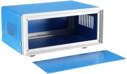
I have a bunch of projects coming up on my bench and I'm interested in box/case/enclosure/chassis providers. I've perused the standard chinese chassis fare on Ebay, I know of Par-metal (and of course Bud and Hammond) as well as the store here, and I found some interesting options on Amazon ("junction" boxes like this one: https://www.amazon.com/gp/product/B09J2935KZ/ref=ewc_pr_img_1?smid=A28DZI5I4PJFY4&psc=1 - image below since this link may not work for long). I'd like to know what other sources you all use for project enclosures.

I've searched here but the threads for this seem to be minimal. I hope I haven't opened a topic that's been addressed a lot in the past.

Thanks much in advance!
Carlp

Attachments

  • Amazon enclosure.jpg
    Amazon enclosure.jpg
    20.9 KB · Views: 126

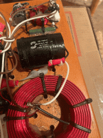
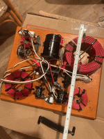
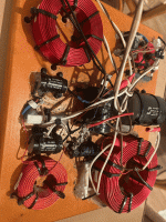
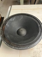
Old VIFA drivers, is it worth building speakers

Hi,

I had a pair of 3-way loud speakers which an audio engineer friend of mine helped me build. I was making furniture at the time and I made the cabinets and he built the cross over network and provided all the plans/specs.

He also gave me an NAD 2600 amplifier which he modified with a huge set of capacitors sticking out of the back, he said they were rare military spec. Anyway, for the last ten years, I've been living with my brother and the whole thing has been confined to my bedroom and so I have not used them much at all.

I've been spending half my time in Greece though and finally am moving there permanently this Saturday. There I have a small 2 bedroom house, the main living area is about 15x25 with a tile floor and 12 foot ceilings. I've got a small klipsch bluetooth speaker which I have been enjoying but am thinking about importing my speakers - the amp has to stay behind because the current is different.

I took apart the cabinets and took out the drivers and the cross over network with the plan to take all that to Greece and build new cabinets there.

It all fits in my suitcase, but I can't take much else and my big question is whether it's worth the hassle, given the age of the drivers, am I better off just buying say a $500 set of speakers that will sound great, not take up too much space and be much less of a pain in the a$$.

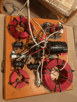
Here is a list of the drivers, and I'll attach an image of the crossovers.

Vifa P25WO 10"
vifa p13mh-00 made in denmark
and the tweeter I can't make out the whole number, H1 ..........-06 27tdfc made in norway

I think if I could sell it all, I would be happier to just let it all go to a good home, but maybe I could end up with some great speakers.

Finally the cabinets I built for these were pretty big, like 24" tall, 14" deep and 12" wide - something like that - not exact - all out of 1" mdf. If I put these in a new cabinet I wonder if I could end up with a decent sounding speaker in a slightly more compact box.

Any advice would be appreciated.

Attachments

  • tempImage8GFBC5.gif
    tempImage8GFBC5.gif
    1.9 MB · Views: 148
  • tempImageOC1k4v.gif
    tempImageOC1k4v.gif
    1.8 MB · Views: 149
  • tempImageo4Sra4.gif
    tempImageo4Sra4.gif
    1.8 MB · Views: 128
  • tempImageudaYEv.gif
    tempImageudaYEv.gif
    2 MB · Views: 143

SF Cremona (first series) - Mid Range

Happy New Year

I have got a problem with one of my Cremona midrange (not the mid-woofer), that stopped working (tested: no continuity). I managed to remove it from the cabinet using the suggestions that I found in an old post (great stuff!). I have a couple of questions though:
1. There are two 4 Ohm Scan Speak possible replacements for the Mid Range:
(a) 15M/4531K (b) 15W/4531K
The physical measurements are the same as the Cremona driver; however, the frequency response are indeed different with the 15M being about 3dB more sensitive.
https://doc.soundimports.nl/pdf/brands/Scan-Speak/15M4531K00/15m-4531k00-data-sheet.pdf
https://doc.soundimports.nl/pdf/brands/Scan-Speak/15W4531G00/pdf_Scan-Speak_15W4531G00_1.pdf
Am I correct to infer that the driver used by SF is the 15M?

2. In old articles and marketing material, one reads that there has been some "customization" done by SF in Italy. However, details are a bit vague... I get the feeling that in reality, for the first series at least, SF customized/adapted the cross-over to these Scan-Speak drivers? These drivers really look identical... Anybody here knows the truth?

Thanks in advance!
Andy

1940s VOT A5 ; 515B, 20ohms, cone repair, DIY

Hi,

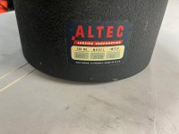
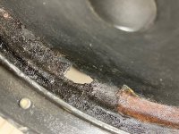
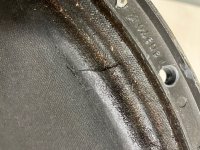
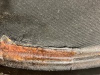
I have just bought part from a mid 1940s Voice of the Theatre A5; the woofer cone has damages, it is a original mid 1940s 515B with 20 ohm impedance.

I would like to try to repair the cone, the damages are located around the surroundings, see attached photos.

I have several questions:

1. what kind of glue should I use, will all PVC glues work, will use a tranparant solution.

2. what kind of material should I use to reinforce the hole, is it a necessity to reinforce this hole at all?

3. all important inputs are more than welcome.

Thanks!

Attachments

  • IMG_2926.jpeg
    IMG_2926.jpeg
    523.5 KB · Views: 101
  • IMG_2927.jpeg
    IMG_2927.jpeg
    433.2 KB · Views: 108
  • IMG_2928.jpeg
    IMG_2928.jpeg
    611.6 KB · Views: 108
  • IMG_2929.jpeg
    IMG_2929.jpeg
    762.3 KB · Views: 101
  • IMG_2930.jpeg
    IMG_2930.jpeg
    667.2 KB · Views: 106

Technics ST-9038+SH-9038 connector

Just wanted to put this out there.

I FINALLY found a MICOM control unit for my Technics FM stereo receiver. I’ve spent some time looking for an OEM connector - anyone know when “Unobtainium” was first discovered? Because it’s at LEAST 40 years old, as are these units.

I had some breadboard jumpers on hand and got to looking at the connector pins, measured one, and the spacing, and thought, “Hmmm?” 2.54mm spacing, pins measure I don’t know how small but they fit with good contact.

These fit. Takes a bit of finessing with a very small pair of needle-nosed pliers and futzing around the 16 of these all connected by a ribbon (don’t separate them), and the LENGTH is way too long, but you can still coil them up (sort of, think roller-coaster) to bring the excess wire closer to the back. I’m thinking of using superglue to connect them all.

I looked around for a connector block, but the WIDTH of the manufactured ones isn’t right (2.54mm x number of pins plus fudge factor of 0.78, IIRC still makes block too narrow to fit pins).

In case anyone else is looking for a solution, or similar application elsewhere.

Attachments

  • IMG_2742.jpeg
    IMG_2742.jpeg
    191.3 KB · Views: 72

Philips CD721 "No disk"

Hello everybody, i have the "no disk" problem on my philips cd721 and i have been trying to fix it for a good amount of time i have once seen a video of another cd player with the same symptoms as me and the guy recommended doing a screw part where it would give more power to the laser
What i have tried/done
Disassembled the entire thing
Replaced the belt
Tested with multiple known working cds while it was opened so i can investigate
I have done no mods to and will not buy anything for the repair
It is not second-hand
Can anyone guide me to the solution above or any other one
I have a bit of understanding of how cds are read but i have not repaired any other cd player
Thanks for helping me 🙂

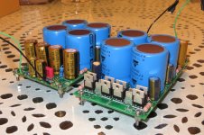
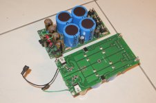
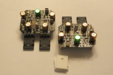
For Sale A pair of (non)regulated power supply for power amplifiers

I have for a sale a pair (2x) of special power supply, designed by talented designer here on forum. This power supply consist of main (non regulated) power supply for amplifier output stage and additional (regulated) power supply for amplifier input stage, which could be few volts higher. In my example, for 2x35Vac input, you get +-50V unregulated and +-55V regulated voltages. Buyer will get full schematic with values, so it would be possible to get other output voltages (with some change of TH/SMD values).

Each non regulated power supply consist of 4x10000uF 63V Vishay main capacitor bank and soft recovery diodes. There is free place for snubber RC components. Regulated power supply works as votlage doubler, which lifts the voltage (in my case over +-80Vdc) after that it follows CRC filtration, before mosfet regulator (IRF610). After that there is additional smoothing/filtration included. All capacitors in this stage are top quality (Nichicon FG, Panasonic FC). Dimensions of board are 145x75x55 mm. Weight is 720 g (pair). I will provide 4 TO220 insulator pads and plastic M3 screws, for easy installation.

This power supply board is ideal for amplifiers where, input/VAS and output power supplies could be separated (ex. Holton amplifiers), providing extra smooth regulated input/VAS stage voltages.

Price is: SOLD + PP + shipping costs (buyer pays any additional custom fee)

PM for details.

Attachments

  • 071.JPG
    071.JPG
    399.3 KB · Views: 269
  • 92 (1).jpg
    92 (1).jpg
    261.3 KB · Views: 268
  • Like
Reactions: NanoFarad

For Sale Pair of Holton HPA NXV200L 4.1 amplifier boards

I have for sale set (2x) of excellent Holton HPA NXV200L 4.1 (4,2) amplifier boards in perfect working condition. This version uses Lateral double die mosfets and accepts balanced input signal. Dimension are 65x78 mm, weight is 120g. Amplifier could be powered with separate input/output stage power supply (good example: https://www.diyaudio.com/community/...ted-power-supply-for-power-amplifiers.405362/). Amplifier with combination of this power supply works magical.

In case you will use one power supply, wire link should be soldered at bottom of amplifier board. Buyer will also receive installation manual and ceramic insulators.

Specifications:
1699629927168.png

1699629959600.png


Price is: SOLD + PP + shipping costs (buyer pays any additional custom fee).

PM for any information.

Attachments

  • 050 (1).jpg
    050 (1).jpg
    265.4 KB · Views: 234

For Sale Spencer D1 V3 board

SOLD
For sale is a full assembled Spencer D1 V3 DAC with
4x PCM63PK
DIR9001 to CS8412 Converter BD
PMD100 to SM5842 Converter BD
I had this one running for a while a few years ago. But I have switched from balanced signal chain to single ended and have no use for the DAC anymore.
I can also add the CS8414 receiver and the SM5842APT I used before the DIR9001 / PMD100.
Open to reasonable offers. Item is located in Germany and I'd prefer to sell within Europe.
Cheers🖖

IMG_7862.JPG
IMG_7863.JPG
IMG_7864.JPG

2020 choice of USB/audio bridge

The task would be considered as trivial until you try. USB/audio bridges, if my memory serves well, were available at the end of 90th from Ti, however, I met almost a military-grade-secret approach if trying to get the application info for USB bridges today, and I was very surprised.
I was interested in a compact low power bridge for a portable DAC, I start to google it and found pretty much nothing. Ok, next I googled for "USB-C 3.5mm jack teardown" and noticed bridges from Cirrus Logic, Conexant and Realtek. All these companies had no such parts officially i.e. they hide all info about USB bridges.. I did contact CL office in HK to get CS46L41-CWZR pdf, they requested my company info and forget about me. After a couple of weeks, I asked again and they apologized about forgot my request, and said - CL will not give you any info about that product, any other chip - you are welcome but not CS46L41-CWZR. Intriguing turn, right? I see CS46L41-CWZR for $5 in Arrow, Digikey, can buy that but have no idea how to use it.
I tried to get some info from Realtek www, I got an email address of my local Shenzhen Realtek agent and ask him about ALC4042/4050. He gave me pdfs the same day, however, the brand new ALC4042/4050 chip has preprogrammed FirmWare with switched off I2S outputs. I asked the agent, could he please turn I2S on? He said - sorry, no time for that complex work which will take 3 months, please, ask another agent I'll give you the contact. Ok, I've asked another "agent" and he said the same - it will take 3 months, we have no time. Well, I'm Russian, right, so I offered him a bribe i.e. cash pay for the FW with turned on I2S port. The guy found the time instantly and asked $7000 for the FW for ALC4050 with I2S is On. Furthermore, he'll not give me the FW file and even programming tool (windows EXE app for programming by USB) but he can program for me all 5000pcs ALC4050 for extra pay, of course, money upfront. I know mainland-chinese very well and asked to show me the ALC4050 sample with I2S/DSD working. The "agent" disagree to prove me he's qualification, and asked me to pay first. At the same time he said a couple of things which makes me believe if he's not really a specialist, he said - Android can not play native DSD just because no way. The bridge I finally use does native DSD256 on Android. Also, the "agent" claims ALC4050 doesn't support 88.2, 176.4 and 352kHz Fs, so I have doubts about how ALC4050 may support DoP DSD in that case??
Finally, the guy called me many times and asked any money I can pay him, I said about we made the decision to go with Comtrue bridge CT7601 + ES9038Q2M because they provide the source code and free Win driver as well. "Realtek agent" said: could I purchase that project, many our customers need that? I do not reply anymore if he calls )) I have no idea who was that moron but I met him because of realtek www, hence due to moronic Realtek management.

Ok, the txt becomes too long, better I'll show you a short chart of bridges I tested:

1) CMEDIA. Doesn't looks active, never reply to my emails, only resend that to their local agents in SHZ. Local agents are ignorant as usual in mainland-china, any tech question will take months of email ping-pong. Also, agents are crazy greedy, they asked me $5 for CM6642 bridge, which I found for $2 finally. The chip(6x5mm QFN) is quite handy just 4pcs 0402 external components required, single power rail 5V, 20mA at 24/44.1. The chip contains OTP for the FW, and CMEDIA gave me win exe app to program IC by USB(BTW, the DLL used with the app was made by Realtek!). However, CM6642 contains the design defect, it has no CRC validation for audio packets, hence, any dust in the USB-C connector may cause a loud noise. CMEDIA product manager said that they can't fix that defect by FW, hence, only the new silicon version may help. Actually, most USB audio bridges(but not XMOS) made on 8051 free core and state machine, hard-logic for the fast USB operations. The FW(8051 program code) may correct some functions but not all.
Pros: compact, low power, no external oscillator required(PLL from USB's 48MHz), single power rail. It doesn't need driver at all.
Cons: SPDIF output only with 24/192 limit. Near to zero support, design defective chip. A quite bad idea to go with cmedia in 2020..

2) XMOS. All app info is opened, well documented. Good support forum, easy to start, easy to modify a custom FW(I spent a couple of days).
Cons: Expensive chips(XU208 PCM 32/384 DSD256 near to $10), no free Win driver. Huge power consumption, 24/44.1 about 110mA, just a lot of surrounding parts. absolutely not suitable for a portable purpose.
3) Realtek ALC4050, it is a combo, the same as CM6642 i.e. DAC+HPA + ADC, supplied with I2S port Off. 6x6mm QFN, single-rail power 5V, a few surrounding parts(5pcs 0402 caps and 1 res) needed to work as USB/I2S bridge. 32/384 DSD256. Core 1.2V, 18mA 24/44.1 consumption. Very low cost, $1.3-1.5. 64kB flash for the FW onboard. Widely used in the new PC motherboards and USB-C/3.5mm jack adapters.
Cons: Zero support, even to get I2S On is impossible(I can On/Off anything in CT7601 source code during a couple of minutes!). In the case if Realtek will offer its source code, it would be the most advanced USB/audio bridge for a portable purpose!

4) Savitech.
Cons: The most secret and most archaic tech at the same time.
Requires NDA to get FW USB programming app, I'm not kidding! )) It is so stupid when you can simply read the FW from the 24C256 where is FW located )) Their www was updated last time 2016, they never reply to your emails. I was sure if savitech simply bankrupt. All chips are 2011, requires 1.8V and 3.3V rails with terrible current, so you need to use buck convertor like with XMOS to make 1.8V >100mA. Even reset is an external RCD circuit, and when I used the Power_good output of my buck convertor, savitech asked to return back their resistor-capacitor-diode circuit! Oh yeah, savitech will ask you for the schematic for the review! )) $5 for the SA9302/9312 32/384 DSD256(to be honest, I didn't see works DSD256 ever with that ICs, only 128). Need wait months to get your "custom" FW, where you actually can not ask for any serious customization at all just product name and LED behavior. Not easy to buy, also needed to fill the form, why you want to buy savitech ICs etc. I see no reason to consider savitech as a USB/audio bridge supplier.

5) Comtrue CT7601CR, actually it is not an ideal bridge as well but they give you the source code(8051 keil project) and free win driver too! All pdfs you can download right now. You don't need a host MCU because all that you need could be implemented by modifying the source code. The chip itself is more technic vs savitech(1.2V core, less current, no stupid external RCD reset etc) but not such advanced as ALC4050 yet. They have different ICs in different packaging, named almost the same CT7601. I use 6x6 QFN 32/384 DSD256(DSD256 really works with Mac, Win, Android) $4.5. 1.8v and 3.3V rails required + one Xtall and few 0402 caps + SPI flash for the FW. Another CT7601PR in the pin2pin same case supports 32/768 and DSD512, as I know $6.5, and cheaper one CT7601SR 32/192 DSD128 $2.5. We asked Comtrue for the HID in/out which wasn't implemented, and they agreed to implement that if we'll give them the app to test HID functions with. Alive people, what can I say.
Cons: so far impossible to buy even in mainland-china. I've ordered 1KU and may offer it on my E1DA Aliexpress store.

6) Cirrus Logic CS46L41, seems needed only 5V as well, very low 24/44.1 current(almost the same current for PCM 384k and DSD128), about the same ALC4050 if not less. Requires external serial flash for the FW. 3x3 BGA case makes PCB noticeable more expensive due to .2mm vias. Also, needed one 22MHz oscillator.
Usually, CL offers two options for the cases so I guess CS46L41 QFN does exist too. About $5/pcs.
Cons: no application data available.

Epilogue: Why many of those companies hide USB bridges from a public domain? I guess we should blame.. Apple inc. When they did delete 3.5mm jack from their iPhone, they created a huge niche for USB/3.5mm jack adapters. Now a lot of Chinese phones goes the same way and the niche reached a few hundred million adapters/year. Suddenly, tiny Taiwanese companies as savitech(I guess it is just a few people, 1-2 is enough to debug FPGA and order the silicon) either not too big US company as CL got the chance to make a big money until big players wake up like Ti, ST, On, NXP, AD. BTW, I've found on AD engineering forum info that AD testing their own high-performance USB audio bridge, hence, I'm right about why that topic so much hermetic today.
Attachments

Will these cases produce the same result?

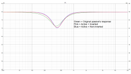
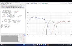
I'm working on a project to convert a passive two-pole crossover to an active four-pole crossover. I've been having fun with the simulations. It's getting close to the end. I've arrived at the sweet spot. It is a transition point that provides nearly identical frequency response curves between two cases--reversed and unreversed polarity of one driver in active four-pole crossover system. Despite having nearly identical FR curves, their phase plots differ. Nonetheless, it begs the question of whether these two cases will produce the same sound that we would hear. In brief, if the FR curves match but the phase curves do not, will we be able to tell the difference between the two cases? Also, this creates a tough decision, so which case do you believe is superior?

Comparison.png

DIY near field and bookshelf/sub?

Would anyone have a recommendation for a near field desktop build and a bookshelf/sub build that would sound good together?

Here's the background - my son and I are redoing his room, I just gave him an old turntable so he's suddenly a vinyl junkie. We have a bunch of left over Doug fir veneered MDF and I thought it'd be a fun project to build some speakers.

His room is small 10 x 12 but the setup is a desk under a loft bed and then a set of bookshelves on opposite wall.

Need to do something small for on top of his desk and then a couple of bookshelf speakers on opposite wall. Thinking about a sub as well.

Anyone have recommendation for a budget build that would sound good together? On the near field could even do in-wall (but not sure if there are diy plans for those).

This is going to be primarily for vinyl.

Appreciate any help. Thanks!
  • Like
Reactions: mayhem13

For Sale Mini DSP 2x4 HD

SOLD

Unit is in excellent condition with no markings or scratches. Includes wall wart and cables, so it's all ready to go into service. This unit is about 5 years old, so I don't know if it's a current model, but everything looks the same as new units. Sorry, I cannot post photos. It looks exactly like what is being sold currently. Will be shipped in original packaging inside additional outer box.

$120 includes shipping via USPS to continental US.

SOLD

Characterizing Audio Output Transformers

I hauled in a bunch of push-pull audio transformers to test on my AC sine wave source at work. I generally test using a 50V, 300Hz sine wave. I monitor the output with a DVM set on AC, and look at the exciting current with a Yokogawa WT210 power analyzer that is also hooked up to the sine source. That way, I can determine turns ratio and from the exciting current, I can calculate primary inductance. I had some unknown transformers that looked good for ~40W (on the hefty side) that tested out at around 6k:8, a pair of "7k:8" transformers that tested at around 6.6k:8, some Baldwin organ transformers that tested out at ~3k:8 (probably wound for 16 ohm speakers), and some bitty transformers that tested at around 10k:8, with not a lot of primary inductance. Next weekend, I'll bring in some Wurlitzer P-P transformers that came off of an amplifier that used 7868 outputs. Fun times ahead, as I figure out how to purpose all this iron...

Reconciliate FIR usage with Grimm LS1 whitepaper

I'm not sure if I raise relevant question or nor, and whether to post here or in the room correction forum. My wondering seems just in between...


I stumbled on the Kii Three and D&D 8c pitch that they can achieve almost perfect operation in "normal" rooms. This seems to rely on the consistent off axis response of the speakers.


Then going through different threads this leaded me to FIR correction as performed with Acourate or Audiolense products (and DRC-FIR for the open source more steep learning curve). This was looking really interesting to improve the system in the room, at listening position. I have bought and read "Accurate sound reproduction" from Mitchco.


Then to Grimm LS1... and the associated whitepaper https://www.grimmaudio.com/wordpress/wp-content/uploads/speakers.pdf . That whitepaper was highlighting the drawbacks/restictions of the FIR approach, especially on the off axis response... Arghh so some promote FIR to solve key issues, but this may impact significantly the off axis response, which is important for imaging and timbre and the secret of LXminis/Kii/D&D.


I started to get bugged about the interest or not to invest time (and money) in FIR correction, either for complete speaker filtering (each driver ground up FIR filtered for listening position) or for final lifting to adjust speakers for listening position.


Is the Grimm whitepaper a bit pushy comparing very different designs related to off axis response (controlled directivity LS1 to MTM arrangement) ?


Can the FIR final corrections be adequate with Cadioid like speakers like my LX-Mini, and would not degrade too much the Off-Axis response?


Is the jury still out, or my problem hill defined ?


(my use case, out of the curiosity/want to learn part, is to have as good performance as possible with my LX-Mini at listening position, in a difficult room (not symetrical, low ceiling, little acoustic treatment possible...).


JMF

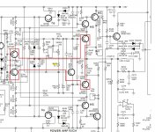
NAD C326bee idle currents problem

Guys, hello.

Here is a story.

This amp is 12 years old now.
I tried to tune idle currents for this amp to be around 3-3.5mA (this voltage is indication of correct idle currents) on each channel. These values are specified in service manual (attached to this post).
Year ago I was able to do this, but it was very hard. Probably because original trimpots were very sensitive, lacking of control.
This tuning inproved sound quality a lot.

But now the amp sounding a bit dead. I read the idle currents values and they went to 5mV and 10mV on channels. So I tried configure the idle currents again but I can not do it any more.
So I decided to replace original trimpots with new (better version)
BOURNS - 3296Y-1-201LF - TRIMMER, 25 TURN 200R
And replacement went well.
And for the first time after replacement I even managed to configure the idle currents to 3.1mV on both channels.
But after couple of hours of listening on average volume the sound went bad again.

But what I see now is :
1) On one channel with trimpot on minimum resistance of 0.5ohm I have idle current is 5.4mV.
If I increase value resistance of trimpot, the idle current goes higher. So no way of getting of 3mV.
On average on this channel the resistance of trimpot is tightly connected with idle current value.
2) On other channel trimpot has value of 120ohm and idle current is configured on 5.4mV.
If I go to lower resistances, then for very long range of them I see no change in idle current, but then it starts to lowering to 4.5mV and then it drops down to 1.2mV. Then, if I go with higher resistances, then again for long time I dont' see any change in idle current and then it jumps up to 4-5mV. So I am not getting the desired 3mV. Such bad not linear behavior.
So, on this channel I see that resistance of trimpot is not very tightly connected with idle current value.


Why such issue can happen?
Do you think that transistors went bad?
If yes, then which once do you suspect?
There are three pairs of transistors on each channel (as I understand).
First pars is small (SMD), second is bigger (vertical PCB mount with small personal heatsink) and then comes the biggest one (Vertical PCB mount on huge heatsink).
But I don't understand (due to lack of experience) which pair is controlled by trimpot and which is not.

Please look on attached schema.
Trimpots have markings of VR103 and VR303.

I measured resistors that are installed in series with trimpots R432 and R232 and they have OK value (slightly above 500ohm, as per spec).
Also both R233 and R433 are fine.

Thanks a lot.

UPDATE from 15/02/2021
SUMMARY OF SOLUTION in my case (for people who does not want to read the whole thread):


The leaking elements were Zener diodes D322, D323, D122, D123.
After replacing them (with MMSZ5231BT1) I got full control on idle currents on both channels.
While replacing pay attention to orientation, see service manual for reference.
Important: don't heat the new Zener diodes for more then 10 seconds on 260C temperature.
260C is enough to solder new diodes in place.

Attachments

  • trimpotsProblem.jpg
    trimpotsProblem.jpg
    193.8 KB · Views: 520
  • c_326bee (1).pdf
    c_326bee (1).pdf
    4 MB · Views: 384

Heathkit AR-1500A

Perhaps one or more of you more knowledgeable folks are able and willing to assist me! I have had an AR-1500A for many years, I built it in 1974. A couple of years ago, I decided to replace all of the caps, and did so. i inadvertently reversed the power supply caps, which of course blew, taking the four rectifier diodes and one transistor with them. I replaced all of the burned items, and now the power supply is fine. However, there are now other problems! When using a 60 Watt light bulb in series with the AC mains, the bulb burns brightly. I removed each PC board, using the process of elimination, and learned that with the Multiplex board and the FM IF board removed, the bulb now glows normally. Of course, I have no FM, that is to be expected. I then temporarily replaced each of the two boards, with known good boards from another AR-1500A, and ditto, no FM, so I now also suspect a problem with the FM tuner additionally. I thought I'd work on the boards first. I began with the IF board, checked each resister and transistor, removing each from the board. All check good, with the exception of Q204 and Q205. Both have been burned. Nothing else appears to be burned. Nothing appears burned on the Multiplex board, but I have not as of yet checked any components. I did remove the six electrolytic caps from the Multiplex board, and with them out of the PC board, I can reinsert the board into the AR-1500A, and no excessive current draw, but of course, not FM either. And with both Q204 and Q205 removed from the FM IF board, I can also reinsert that board as well, with the same outcome, no FM. Amplifier sections works normally, as does AM. I only have a variety of multimeters for testing, perhaps one or more of you could direct me to a suitable capacitor tester for purchase. I see many advertised, most require 1-2 months from China to be received. Any comments at all would be appreciated. Thanks much

Howard Spivak

Ghost duplicate m4a files in folder?

In folders of music by my daughter I noticed there are duplicate m4a files that do not play but start with ._track number (eg ._01). I know she did these via iTunes on her Mac where my files via iTunes on Windows do not have these. I tested by deleting these files and had no detrimental effect and have nothing to do with album art. What are they (see example below)?

ghost_aac.jpg

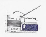
Are these data sets sufficient to custom-build drivers?

I wonder whether these data sets, together with the voice coil construction image, are sufficient to allow the driver manufacturer, probably a modern Chinese company, to build a driver.

Driver type: dynamic
Cone diameter: 10 inches
Cone material: copolymer
Surround material: butyl rubber
Impedance: 7.6 Ohms
Voice coil diameter: 2 inches
Voice coil former: Kapton
Magnetic flux density: 0.9 Tesla
Magnetic flux: 1.17 x 10^-3 Weber

IMG_7623.jpeg

Credit for picture: tysontom of “classicspeakerpages” forum

Vacuum cleaners

Not sure how many of you boys do the vacuuming around your place but I am one of them. My wife is unable to so I'm the man. We had a Dirt Devil upright corded unit that we bought new 10 years ago. Because of my right side injuries, it was becoming quite the nuisance. We have laminate floors with lots of runner carpets and area rugs. Adjusting the roller brush height was an ongoing job.
I used the old vac for the last time and then ordered a Dyson cordless on Sunday as they are having the Black Friday week long sale. It arrived 2 days later and just for fun I decided to run it over the carpets that had been done 2 days prior.
I could not believe my eyes when I saw the amount of dust and dog hair that it picked up from recently vacuumed areas.
I am now a walking advert for the Dyson V10.
Okay, enough said. You guys don't really want to hear about vacuums anyway, unless of course were talking tubes. 🙂

Intermittent noise on one channel of preamp

Hi gang,

I've been a lurker around here in the past and now have a need for some specific help.

I recently purchased a mid-90s Conrad Johnson Premier 14 tube preamp. I am getting a static-like noise in one channel, then some frying egg type noise that usually ends with a mild pop. Then the pre settles into the static noise, repeating the egg frying pop again. I don't perceive a change in loudness of the noise with volume on the preamp and input source or no source have no effect. The previous owner had noted this noise as well and stated it went away after a few minutes. I have listened to it for 30 min or so and still didn't hear it calm down, though it seems to get less frequent with the pops as time goes on. Last night I decided to let it stay on for an hour or two before listening and then it was quiet. No static, nothing for the next couple hours I listened to music.

Diagnostics done so far: swapped tubes around L to R, and mixing the tubes front to back (there are 2 per channel). Noise seems to always stay on the left channel. I pulled the tubes in and out about 20x and gave then a brushing with the dental flossers and I will pick up some Deoxit this weekend. I retensioned a couple of the socket connections as one socket (on the left) seemed looser than the other 3. I have used the chopstick method and nothing changes the noise. I did feel like one time when the frying was actively happening wiggling at tube might have changed the sound, but that could have been coincidental.

Some info on the pre: It uses two 6GK5 tubes per channel, which mine are currently a mismatched pair of mullards and another brand. The volume control is a series of resistors and relays, effectively making a step attenuator. Vishay metal foil resistors and CJ poly caps in most everything short of the power supply.

What do you guys think I should test? I do need to get a complete new set of tubes just in case I have 3 bad of the 4. I am a little knowledgeable on working with electronics, enough to know how not to get shocked and I am handy with a soldering iron. I have read a ton on this and plate resistors come up a lot. Is there a way to test without unsoldering? Can I pull the tubes and check resistance or power up to check the voltage to see if L and R match?

Thanks
ben

faulty ir21844?

so i have a esx signum se7000d that i been working and learning on. So after changing some bad parts the protect light is now solved however the output relay are not being engaged, sometime it engaged and would dissengage soon after. twisting or bending the pcb wouldnt do anything,then i recently came over this tread https://www.diyaudio.com/community/threads/crunch-class-d.395669/page-2 where they talked about shutdown pin2 on ir21844 which where internally supplied by 5v which i did not have after removing pin 2 from ir21844. before removing pin 2 it was about 2.5v referenced to terminal ground and after removing pin 2 it dropped to 8mv but had 5v at transistor which connects throught a resistor then to pin 2. after changing ir21844 i still had no 5v on pin 2 but somehow the amp engages the relay and stays on like normal with sound output.
why is there no 5v on pin 2 and i am worried that reconnecting the transistor to pin 2 that it will blow like all other ir21844.

Finally Giving These "Laidys" a Try - Not Too Shabby

Back in 2020 I was building my SSE and chose Transcendar OPTs for the build. Some may remember that I also got a crazy good deal on these Chinese "Laidys" OPTs https://www.diyaudio.com/community/threads/rolled-the-dice-on-chinese-opts.348858/post-6422961

Recap: They weigh in at 990g, cost me ~$80 CAD total (for both, including shipping) and they are ugly AF. 5K primary and 4/8ohm secondaries (with UL tap). 38 Henries.

I plan to build a TSE-II (w/45s) and I am gathering parts. Apparently, Gery isn't winding the Transcendars anymore. It occurred to me that I could rob the Transcendars from my SSE and use them in my TSE-II build, and swap the "Laidys" into my SSE.

So, that's what I did. This is the first time I have ever even heard these OPTs and I must say they are quite decent. Everything from lows to highs all sound perfectly pleasant to me, even when I push some fairly loud SPL. I will give them a more thorough listen this evening.

I'd like to say it is hard to find fault, but it isn't. They truly are the ugliest OPTs I have ever seen. Would be a great OPT if "sleeper" amps were a thing. You know, like those sleeper cars that look like a piece of junk but have 600hp under the hood and can do 0-60 in 5 seconds.

The bad news? Sellers on ebay seem to be asking around $90 each (incl. shipping) for these same OPTs now.
  • Like
Reactions: Francois G

Re-capping HCA-1206

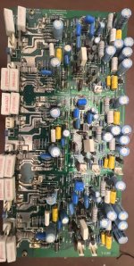
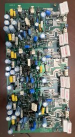
I am recapping HCA-1206 and i would like to perform all work that was done by @Tsipkin in following post. Is there someone who can provide part list for it? i got the basic caps down but i can figure out other parts that i should replace. Any Mods you can recommend to better the sound are also welcome. This is my first time i have good friend who can replace the things for me and he agreed to do it 🙂 but i just need to know the parts and things i should replace. There are 4 bord. 1 seems like power supply 2 are for Chanell and one small by the input.

My current List
47uf80V X 48
10uf80V X 2
1000uf100v X 2
220uf100V X 2
220uf100v X 4
220uf25v x 1

https://www.usaudiomart.com/details/649982032-parasound-hca-1206-amplifier-fully-upgraded/

Attachments

  • IMG_8977.jpg
    IMG_8977.jpg
    622.1 KB · Views: 123
  • IMG_E9012.jpg
    IMG_E9012.jpg
    399.5 KB · Views: 116
  • IMG_E9014.jpg
    IMG_E9014.jpg
    446.9 KB · Views: 106

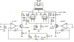
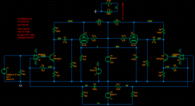
Hybrid Transimpedance Tube Amp Sim

@ jhstewart9 posted this schematic of a Hybrid Transimpedance Tube amp a couple of days ago : https://www.diyaudio.com/community/attachments/transimpedance-amplifier-hybrid-jpg.1158737/

It was presented in Wireless World Mag Oct.1995. I only found a poor, blurred copy of the article and a schematic with all the component values (attached).

So far I understand it the transimpedance part is buried in the sand and not in the vacuum.

Anyway, over the weekend I put it into LTspice but the result was devastating:
  • extremely distorted output even at low levels (claims are 32 W and 0.07% THD at 20 W)
  • phase splitting is not working properly (quote from the article: "Phase splitting is produced by coupling inverting inputs A1 and A2 together via R11 and C4. This results in two antiphase equal amplitude signals to drive the output stage." unquote)

This is not the case in my sim (attached)
Tried 3 different opamp models TL082, OP07, NE5532 to no avail.

Questions:
  • How is the phase splitting supposed to work ?
  • And why does it not work in my sim ?

Attachments

  • TIAmp.jpg
    TIAmp.jpg
    35.8 KB · Views: 337
  • TRIA.png
    TRIA.png
    20.8 KB · Views: 328
  • TRIB.png
    TRIB.png
    16.5 KB · Views: 319
  • Draft45.zip
    Draft45.zip
    1.7 KB · Views: 79
  • EW_WW_10_1995.pdf
    EW_WW_10_1995.pdf
    986.4 KB · Views: 119

Power Transformers for Solid State Amplifiers - Toroidy vs.Tauscher and Plitron - who have tested ?

A friend of me use since any months for his no longer available Kaisaya power amp units (Accuphase E505 clone) - go to
https://webcache.googleusercontent....005002934655996.html&hl=de&gl=de&client=opera
a power transformer from this series:
https://sklep.toroidy.pl/en_US/c/To...EME-AUDIO-GRADE-V2/99/2/default/1/f_ov_8_78/1
this version:
https://sklep.toroidy.pl/en_US/p/TT...ade-transformer-TSAS1500VA-voltage-to-50V/427
No mechanical hum and very good sonic performance are recorded.

This brands are also known for good quality, but more expensive:

1) Tauscher (Germany)
https://www.tauscher-transformatoren.de/assets/pdf/R_11.pdf
https://www.tauscher-transformatoren.de/assets/pdf/R_14.pdf
2) Plitron (Canada, now Noratel)
https://www.noratel.com/news/news-e...nounces-rebrand-of-plitron-manufacturing-inc/
https://www.noratel.com/products/type/bespoke-oem-design/
https://web.archive.org/web/20050223084832/http://www.plitron.com/ (go to products, then "low noise transformers")
https://web.archive.org/web/20050215093935/http://www.plitron.com/pages/technote.htm
https://web.archive.org/web/20130705130420/http://www.plitron.com/

Could it be that these brands have a number of further advantages (like e.g. an integrated snubber network) that one don't find at Toroidy?
Thanks for any information.
check out also this threads:
https://www.diyaudio.com/community/threads/what-makes-a-good-audio-power-transformer.12611/page-3
https://www.diyaudio.com/community/...rmer-snubber-using-quasimodo-test-jig.243100/
and page 103 from the attached PDF

Attachments

What is the method for determining optimal crossover frequency for waveguide I've designed

Hi all,

I've designed a biradial waveguide for my tweeter in CAD (linear horizontal expansion and exponential vertical expansion). Looks great, although I can't quite get my head around how I would could the ideal crossover frequency for it. I've analysed it in AKABAK (using youtube tutorials) but not quite sure what I'm looking out for. Tried searching google but the results I get aren't quite what I'm trying to ask - maybe I'm wording my problem wrong.

I'm trying to optimise a wide directionality for an open sound.

Fairly new to DIY speaker design and building, and very new here so apologies in advance if I've posted this in the wrong area.

Any nudge in the right direction would really help.

VFet SET headphone amp

Taking a break from tubes, one is naturally drawn to static inductive transistors. The specs are what tubes could only dream of and would enable the most compact two stage and high quality headphone/speaker/linestage. Luminaria was a great paper to get my feet wet and so an idea emerged, why not treat them like tubes? After much planing this project came to life:

1704295413013.png


The resolution this amp brings was hard to believe and a punch in the face to my tubes4life mentality.
2SK79 is running at 4.5mA and should have 2K rp, the AVC takes care of the input capacitance of the 2SK82, not only is it a volume control but at my listening level the output impedance is well under 100ohm, Pass recommends under 600.

The UTC LC-33 allows for fine tuning of the output and input. The return to cathode works really well with the caveat of floating output.
20240102_210134 (1).jpg

Advice needed on turntable motor replacement

Hello, I have a modified AR EB101 turntable that sounds good but I have the common problem of the 12-stepped AC motor on the way out! It looks like I must go the DC route which is easier than fitting another AC motor but do not want to buy into the Origin Live setup.

I want something that quality-wise is going to fit into my system so I am looking at a Maxon 110945, for speed control a Motor Speed Controller PWM Regulator on eBay, and I already have a TeraDak 30W PSU Regulated Linear Power Supply DC24V. I am assuming the motor controller will work with the motor.

Any advice would be appreciated - Thanks

Can you switch from a cloth surround to foam?

I've recently refoamed a Hertz ML3800 because the surround was cracking (https://www.diyaudio.com/community/threads/rubber-coated-cloth-surround-cracking.395384/).

Before the operation I measured the TSPs and they were a bit off - but not by too much. I didn't save those but I remember the Fs being around 42Hz and the Qts being around 0.6. I thought that replacing the surround that looked in a very rough shape would help.
It didn't.
In fact I made it way worse. The parameters are unusable. The Vas is basically halved and the Cms too. Qts skyrocketed to 0.8. The SPL dropped too. I remember I measured 93dB.
The TSPs were measured after about 10 hours of break-in at Xmax with a 10Hz tone.

I think that the surround I installed is way too stiff, however it was the only one I could find which looked similar enough and was of the right size and the same material.
I was thinking that if I swapped it for a foam surround (or rubber, if I could find one of the right size) it would be much softer and it might help.
My guess is, however, based on absolutely nothing, and a Google search wasn't successful either. I fear that this operation might be of more trouble than it's worth.

I wanted to ask if anyone did a similar operation and therefore could share how it turned out.

The driver in question has a "double" center spider, even without the surround it is very stiff and doesn't "sag" at all.
I'm attaching the TSPs of the disaster

Attachments

SqueezeCore: a minimal audio OS running Squeezelite

SqueezeCore is a project that I had in mind for a long time for personal use.
Now that it's "finished" (aka working) I thought it was worth making it available to anyone.

The main purposes that I have taken into consideration are: a comfortable, fast, plug & play os, which requires (pretty) no configuration and reduced to a minimum to be installed on a thin client (or other low power hardware) used as a player.

The result is an o.s. of 17MB which runs on ram.
The first time it is turned on, a quick configuration of the squeezelite parameters is required (which is optional, it can be avoided by directly editing a file while preparing the USB drive); after this, at every boot and on any computer you'll plug the USB flash drive containing SqueezeCore you can start listening to music in 3 seconds.

Of course, since SqueezeCore is working only as a client you need, as prerequisites, another computer with a Logitech Media Server installation.

Download and installation guide: SqueezeCore

it's still in "beta" because I've tested on a limited amount of devices. Feedbacks appreciated.

UPDATE 20/02/2020

I have released a version with a custom RT kernel.

From the FAQs:

"It is a specific build with a custom Real Time kernel; the hardware requirements are different from the generic version:
Minimal Hardware Requirements for RT:
CPU: Only Intel, Only Core2Duo and newer (Xeon, Core i3 i5 i7, new Pentium and Celeron). 2 core 4 thread (recommended 4 physical cores).
The Other requirements are the same of the generic one.
In the RT version the difference is not only in the kernel but there are other tweaks under the hood like:
The player runs on a isolated core with round robin scheduler.
All the DAC USB interrupts are isolated on one core.
The remaining core are for kernel and the remaining interrupts and software running."

UPDATE 08/07/2020
New release of the RT version. Added the option to configure a static IP

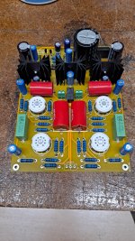
eBay 12AX7/12AT7 preamp

I recently gave my granddaughter my Sony STR5600 and Kenwood KL5050 speakers which she has been begging me to give her for years. I had been using it in the bedroom as a stereo/TV sound system as I have some hearing loss and the speakers in most TVs are lacking for me.

So, I moved my spare 6P41S SE amp and FF125WK speakers to the bedroom, but found the amp does not have enough gain (TV output is very low and I had to crank the STR5600 past 3 O-Clock to hear it).

So I now need a pre-amp. Rather than design one, I decided to see what I could pick up from the Bay of E's for not so much.

I came across one advertised as "HiFi 12AX7 +12AT7 Tube Stereo Preamplifier Board Base On MATISSE Preamp".

Un-assembled kit for $40 plus $4 shipping. I messaged the seller for a schematic and received one several days later.

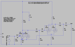
After entering it into LTSpice, I was pleasantly surprised to see that the distortion at 0.5Vrms out into 100K (6P41S input pot) was quite reasonable at 0.0004%. I was originally planning on redesigning it to use a different output tube, maybe a 12BH7 for better drive and load tolerance. After simulating it I decided to go with it as is for now to see how it sounds.

As it stands, I am waiting for some connectors to arrive to finish the build and start testing.

I was not able to find any reference to this board in searching the site.

Full construction time was less than 2 hours. They just don't supply input and output connectors, although the spacing supports them.

Has anyone else built one?

The design is basically parallel 12AX7s common cathode circuits cap coupled to parallel 12AT7 in common cathode with feedback from the output back to the cathode resistor of the 12AX7 stage.

Attachments

  • 20240102_211122.jpg
    20240102_211122.jpg
    541.2 KB · Views: 175
  • LTspice_12AX7_12AT7_.png
    LTspice_12AX7_12AT7_.png
    20.3 KB · Views: 233

Using “Apple TV” as music streamer, anyone?

I’m using Museatex idat44 DAC in my system. It has optical and coaxial inputs. I connect the coaxial input to Yamaha YBA-11 bluetooth receiver and inexpensive Android TV via optical input. After living with them for a period, I recognize that it’s time to upgrade the source. I will keep the YBA-11 in place, but the Android TV. Are there people using Apple TV as music streamer? The new generation Apple TVs no longer have optical output, to use it as an audio source, HDMI output port is the only channel to deliver signal. In brief, to connect the Apple TV to my DAC, it requires to connect Apple TV to the Android TV via HDMI first, then, from Android TV to the DAC via optical cable. The question is will the digital audio signal received by the DAC belong to “Apple TV” or “Android TV”? Remember the objective of this attemp is to discontinue the use of Android TV as a digital audio source and switch to Apple TV instead. So if config the system as mentioned, Apple TV —> HDMI —> Android TV —> Optical —> DAC, will it considered to be the upgrade? Finally, is it worth to invest the Apple TV for this purpose?

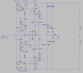
CFA headamp development

Hello there,

I'm playing around a CFA headphone amplifier. I was inspired by Accuphase amplifiers to try with CFA design. My friend from https://muzgaudio.com/ helped me to get going (thanks Konrad!), but he can't give me all his free time (which I understand). I'm a beginner analogue designer and a hobbyist.

The concept is to deliver 2W@64Ohms with THD+N below 0,001% for 1kHz. Currently, I'm at 0,004%.
The compensation is taken from the famous article by Mr. Alexander: https://hifisonix.com/wordpress/wp-content/uploads/2012/09/The-Alexander-Amplifier.pdf

cfa-hpav4.png

The amplifier is not considered stable yet! It is not calculated, just a placeholder.

The topology consists of a diamond buffer in Marantz HDAM 3 topology, a Widlar current mirror and a 2EF.

Operating currents are described in the sim. Please feel free to download and play around with it.

There is a weird distortion in the current between first pair of emitter followers (Q7, Q9):
distortion.png

Can somebody advise? The sinusoidal current in VAS side, degeneration resistors for current mirrors also seem to not be symmetrical (e.g. I R22).

Still to do:
Baker clamps
Bias generator
Compensation
DC Servo
Output stage bias tuning

Attachments

  • Like
Reactions: lineup

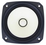
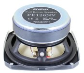
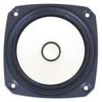
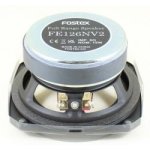
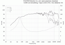
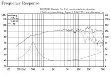
Fostex’s newish line FE126NV2 drivers vs FE126NV older drivers? That was fast?

So I went on Madisound website and was looking for a new project and came across the Fostex Driver’s page and noticed a few weeks ago the Newer FENV line is now updated to the FENV2 line models. That was a short lived updated FE line update. What I got from the update : By eliminating the metallic eyelets new FE-NV series offer reduced harmonic distortion in the midrange. The pocket neck damper developed in the FF-WK series has been adopted to continue the three-point bonding of the voice coil and the damper and cone paper on the same circumference. The shape and material of the dampers have been reviewed for more linear amplitude characteristic than the current FE-En series. Also not shipping paper out with specs. and down loading the specs. on the fostex website. So I guess am posting this to ask if anyone has done any side by side listening or comparisons between the FENV vs FENV2 speakers. I added pictures of both drivers and frequency graphs of both drivers. First graph is the older FE126NV and the 2nd graph FE126NV2 drivers. Jeff

Attachments

  • IMG_2749.jpeg
    IMG_2749.jpeg
    64.3 KB · Views: 216
  • IMG_2750.jpeg
    IMG_2750.jpeg
    68.8 KB · Views: 159
  • IMG_2747.jpeg
    IMG_2747.jpeg
    10.9 KB · Views: 160
  • IMG_2748.jpeg
    IMG_2748.jpeg
    12.3 KB · Views: 213
  • IMG_2751.gif
    IMG_2751.gif
    51.1 KB · Views: 225
  • IMG_2752.jpeg
    IMG_2752.jpeg
    48 KB · Views: 224

Hypex Ncore mute on startup - custom input board

Hi there. I am making a DIY build with some Hypex Ncore NC500MP boards. There will be a couple of amp modules in a box with custom input PCB for signal detect auto power on, 12V trigger IO, and temperature monitoring.

I was thinking of adding some kind of soft start functionality, i.e. have the amp modules muted on turn on/off, to reduce pops and/or speaker damage. At the moment, this is done by using the amp power good signal to control the amp mute input. Is there any point in doing this if I am controlling the amp ps enable line to bring amp modules in and out of standby mode. For reference, the amp module datasheet is here: https://www.hypex.nl/media/90/08/74/1646057938/NC500MP_04xx.pdf.

If anyone has any comments, suggestions, advice, that'd be much appreciated.

How much does Center-to-Center distance matter

I have a pair of QSC HPR152i clones along with B&C DE250 drivers. The horns are 14"x10" horns. I also have a pair of JBL 2226H.

I'm curious to know if there are any obvious warning signs before I start making sawdust. Specifically, I am concerned about the center-to-center distance between the CD+Horn and the Woofer. I've read before that the CtC distance should not exceed the crossover frequency.

The closest I can get the center to center distance is 12 inches, and that's with overlapping the horn and rear mounting the woofer.

12in = 304.8mm, which corresponds to a wavelength of 1,132Hz. I'm not sure if that horn+tweeter combo will play that low.

As I was perusing through Troels website trying to find an implementation of a waveguide in a speaker design, I came across his Quattro 2-way speaker.

In that specific design, the crossover frequency between the waveguide loaded tweeter and the woofer is 2.5Khz. The wavelength of 2.5khz is 137.6mm. The center-to-center distance per Troels website was 170mm.

Obviously Mr. Troels knows what he is doing and I'm sure he is well aware of this general rule of thumb. So there is clearly something at play that allows flexibility (maybe trading one benefit for another).

Thoughts?

How does this driver handle as low as this frequency?

I found a vintage speaker pair has quite weird specification. They’re ADS L1590 speakers. Their specification shows they have woofer-to-midrange crossover point at 350Hz. However, the midrange used is merely 2-inch dome!

So, I don’t think this is the -3dB point of the dome midrange. Instead, it might be an actual crossing point between woofer and midrange, I don’t believe there are any 2-inch domes could handle that low frequency. Is my assumption correct?

If so, the next question is about the roll-off. The crossover schematic also shows the filters are second-order configuration on every section. The question is if the second-order high-pass filter was applied to that 2-inch mid-dome at -3dB point of its natural roll-off, the acoustically combined response of the mid-dome (high-pass section of the mid-dome) should be 24dB/octave instead of 12dB/octave (first 12dB from the filter and another 12dB from driver’s natural roll-off). Is my second assumption correct?

2,5 or 3 way?

I will make a slim speaker with six identical 5 1/4» midwoofers.

It will be MTM on top. The question is 2,5 or 3 way?

If it will be 3 way i assume serial-paralell wiring og the 4 woofer drivers is best?

But if i choose 2,5 way, how should i wire the woofers then? Could it also be an idea to shade pairs of woofers with different lowpass?


IMG_8751.jpeg

NAIM AV2 tantalum re-cap

Hi all, I have a naim AV2 I use for AV and realising its now 20 years old I decided to treat it to a recap of the Tantalum caps as I understand these are the units needed replacement at the recommended service interval.

I have my naim power and pre-amps serviced 'normally' and quite capable of doing the work, but for some reason wanted to keep the main amps serviced with correct parts etc. Anyway my question is I have 34 tantalum caps to be replaced all 10uf 35V and I have the correct replacements but after taking 6 out, I have realised they are all very well marched (more so than my 5% replacements) and all measure 11.2uf and all measure the same or close ESR to the new units I have bought. So given I am about to spend many hours carefully removing and adding 10uf (that mostly measure 9.9uf) with similar ESR am I just about to burn £100 and a day or so of fiddling to achieve nothing ?

Any advice on the Tants and perhaps some take more wear than others I did pull one off near the regs as this is feeding the +- 15v Opamp rails and this measures, 11.2uf and bang on for ESR as well. Are naim just avoiding premature failure with the 10 year replacement, I had understood the ESR normally raises before any failure ?

I2S lines resistors

Hi All,

I have a question regarding resistors values that are in between a digital filter and the Dac chip I2S input.
I've noticed that the resistors values are different in every CD player or Dac, some use 300r, some have 1K, some don't have any resistors at all.

I would like to know please why there is a difference and how the resistors value affects the Dac ?

Thanks

Attachments

  • I2S resistors.jpg
    I2S resistors.jpg
    267.9 KB · Views: 190

Transformer Lead Twisting

I am wondering how to best twist transformer leads? There are the heavily insulated manufacturer installed leads like from the LV secondary winding or the primary windings. A lazy twist seems ok but further twisting seems like it maybe stressing the connections inside the bells. Also the tighter the twist the more the pair of leads wants to coil up on itself - looking non-professional.
These are Edcor type units.
Thanks

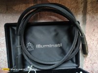
For Sale Illuminati DX-50 AES/EBU Digital cable(a piece of Digital history)

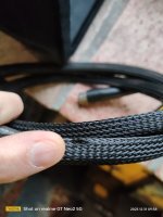
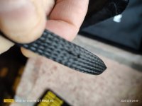
A piece of history! I dont have White paper on this but my Memory says those are One of the First Digital cables of Mr. Chris Sommovigo ,ante kimber orchid that should be its commercial effort.
The cable Is 1,5mt lenght and Is serial numbered. It has the original "Illuminati" packing box. . The cable has two small break on the overall cable mesh sleeve that are shown in pictures. But the cable Is internal to It and its perfect. A piece of history! 200 Eur + shipping

Attachments

  • IMG20231231093827.jpg
    IMG20231231093827.jpg
    676.1 KB · Views: 93
  • IMG20231231093810.jpg
    IMG20231231093810.jpg
    422.7 KB · Views: 87
  • IMG20231231093853.jpg
    IMG20231231093853.jpg
    317.7 KB · Views: 88
  • IMG20231231093932.jpg
    IMG20231231093932.jpg
    242.8 KB · Views: 91

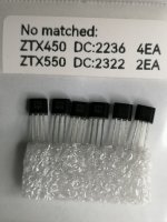
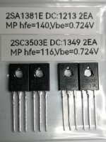
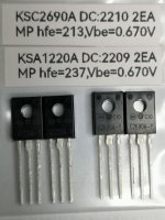
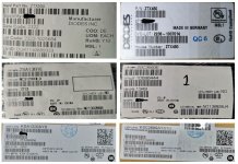
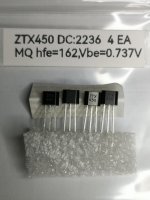
FS: BJT set for new Stasis FE (ZTX4550/ZTX550/SA1381/SC3503 or SA1220/SC2690)

Sale BJT set for the new Stasis FE (new design by NP).
The set consists of:
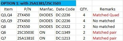
1. ZTX450 DIODES DC:2236 4EA (matched quad)
2. ZTX450 DIODES DC:2236 4EA (no matched)
3. ZTX550 DIODES DC:2322 2EA (no matched)
4. 2SA1381E ON DC:1213 2EA (matched pair) and 2SC3503E ON DC:1349 2EA (matched pair) Called OPTION1
or
5. KSA1220AY ON DC:2209 2EA (matched pair) and KSC2690AY ON DC:2210 2EA (matched pair) Called OPTION2
all matched TRs are measured by hfe +/-5 and Vbe +/-5mV by using DCA75.

Sale price @ US$18.06 per set for both options.
+ shipping cost (ship by registered airmail from Thailand).
Payment via PayPal only.

If you are interested please PM me.

Attachments

  • 1.ZTX450_MQ.jpg
    1.ZTX450_MQ.jpg
    257.2 KB · Views: 102
  • 2.No matched.jpg
    2.No matched.jpg
    293 KB · Views: 97
  • 3.2SA1381_2SC3503.jpg
    3.2SA1381_2SC3503.jpg
    297.2 KB · Views: 108
  • 4.KSA1220_KSC2690.jpg
    4.KSA1220_KSC2690.jpg
    288.8 KB · Views: 110
  • 5.BJT for new stasis FE.jpg
    5.BJT for new stasis FE.jpg
    119.5 KB · Views: 102
  • 6.DCA75.jpg
    6.DCA75.jpg
    118.3 KB · Views: 108
  • Option1.jpg
    Option1.jpg
    27.9 KB · Views: 100
  • Option2.jpg
    Option2.jpg
    28.3 KB · Views: 100

Nobsound NS-20G amplifier will work on 3 ohms

My nobsound ns-20g amplifier dosent show any signs of overheating or lot of disturbance only little bit on high volume I have connected two bookshelf speaker 35w+45w both are 6ohms connected in parallel configaration which goes to 3 ohms
Per channel

My amplifier specs

Nobsound ns-20g
the output power is improved to 200W (100W*2) with 2PCS TPA3116 chip
Suits 5-8 inches / 4-8Ω / 20-120W speakers

Any suggestion for modification of Hiraga Preamplifier Le preamplificateur Kaneda

Greetings all,

This is my first thread here but I have been a long time reader and learned a lot. I have been an owner for the Le preamplificateur Kanda I have assembled it from the kit back then and I have upgraded the filter capacitors few years back and I am really happy with the sound. However, now I am looking to do some modification and I would be really happy to be advised and guided by your experience. this is the Document for the preamp I have installed and aligned as per the instructions with great help from friends. the sound is great especially in the low frequency it makes my Technics Sb-500 ring the room. I believe the unregulated power supply section is fine unless you have a new idea. please see the picture below. please see the picture.

looking forward to hear your ideas.


Thanks
Ahmed
FC792870-E1E8-41D3-AA58-F832684769E7.jpeg

Attachments

Global feedback stability improvement with current feedback

I've had success in making two valve amps with global feedback unconditionally stable, compared to original operation showing unstable operation with certain capacitance only loading. The technique used follows on from Patrick Turner's use in two restorations (a Dynaco MkIV and a 100W UL monobloc). Sadly I didn't get time to discuss this topic with Patrick, but was pleased to follow his lead and test the concept in a Williamson amp last year, and just recently in an Encel X1212 stereo 12+12W valve amp from mid 1960's (aka a Star SA-30 from Japan).

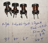
The technique inserts a small low-value inductance in series with the normal voltage feedback signal, such that load current passes through the inductor, as shown in the example schematic below. The inductor used was a modified 22uH open-wound ferrite slug type, with turns removed to get down to circa 1-3uH. I compared stability performance in the Williamson, with results in https://dalmura.com.au/static/Williamson output transformer measurements.pdf.

The Encel amp was unstable with certain capacitance only loading, but otherwise stable with its 13dB feedback as it uses a heavy step network on the input stage to roll off gain. I wasn't able to improve on the stability performance with simple capacitor compensation across the feedback resistor, but didn't go further down that path. Instead I deployed a 2uH inductor and was able to achieve unconditional stability even after removing the step network (which was my aim if practical).

The inductor I used was quite small, and very simple to retrofit in the Encel, and in some amps it may be quite easy to implement. So I can recommend it when squarewave testing is available to check stability.

Ciao, Tim

Feedback circuit options.png

Attachments

  • Inductor ELC08D220.jpg
    Inductor ELC08D220.jpg
    521.4 KB · Views: 119

Dovedale 3 Tweaks

Newish member here. I have been reading lots on this site and I have learned a lot. I recently acquired a pair of Dovedale 3 from a CAM member for 200 CAD because his technician said that one of them may have a short in the wiring after one channel of his vintage Sansui amp blew. I have put them on a DATS and they measure as I think that they should, so I went ahead and hooked them up.
The cabinets are immaculate and I believe that they are untouched internally but I have not had a look inside. I am used to listening to full-range speakers of various sizes in well-designed enclosures and I like that sound, generally.
What I find with the Wharfdale is that:
The midrange blends well into the high frequencies but the midrange lacks detail and the high frequencies don't sparkle. The bass is kind of wooly and muddy. This is the biggest disappointment as I expected the 12" woofer in a sealed enclosure would give me tighter bass than my Spendor BC1 (recapped). I attached a Schiit Loki and set the 20hz pot to its lowest setting which helped a bit; I am not a bass-head but do feel that I am missing something this way. Playing with the other 3 EQ pots did not improve anything. I have left the rear panel controls for mids and HF at "increase" as I wanted to keep the old resistors out of the circuit. That is probably where I would want them anyway.
On the plus side, there is no ringing on percussive high notes on piano; something that drives me crazy.
These are about 50-year-old speakers and I realize that one usually recaps at this point but I don't just want to throw in new parts as the protocol. I would like suggestions as to the order of operations to improve the above "faults", if possible. I have tried driving them with a big Perreaux amp as well as various Class D amps; Icepower and TPA3255, with a Schiit preamp. That doesn't seem to make much difference.
I look forward to your opinions and suggestions.

Help to choose new Baby Labs driver

I have some Woden Lance with FF85wk and want to move to something larger in the Baby Lab series. (but open to other suggestions)

The budget for a driver is up to $50ea and looking for some options. It's for near-field, 6' away and it's a 2.1 chip amp with a voxel sub.

I don't see the MA 6.x series anymore.

Going up to the FF105wk does not seem like it would be much of a change.

That leaves the CHN-70 and the Pluvia 7 - Can someone compare them and explain to me the "Japanese" tuning I saw mentioned? Not sure that is something I'd like if I'm reading it right.

The Storm Shadow just says Pluvia 7 - Is Pluvia 7 PHD the right one?

dsp crossover design

hello to everyone,
i have designed a 3-way croosover for my active speaker system using minidsp (minisharc). I was just playing with the Vituixcad2 simulator and the crossover i have designed. My crossover is on the picture with the midrange inverted. I am reffering to the low-mid section. Look at the drivers delay. It seems that the woofer must be delayed by 200uS to get the deepest null. One would say that the midrange should be delayed to get that null. All the measurements that i made are 1m at the tweeter level. Now the speaker is working without any delay at the mid or low regions. the total SPL is exactly as the program simulate, so everything seems to be ok. I just thought to play with the low to mid section time aligment and found this. If i connect the input of the low section after the Mid Low pass filter, as i would do if i were to design an analog active crossover, then the midrange section is the one that should be delayed to get the same null. So if i understand correctly the two filters in series in the mid section, introduce larger total delay to the midrange section so finally the low section must be delayed? I suppose that in the minidsp the logic is that the sections are independed between each other, as on the picture, am i right?

Attachments

  • Screenshot 2024-01-02 at 23.14.12.png
    Screenshot 2024-01-02 at 23.14.12.png
    176.2 KB · Views: 107

New 2M (78 inches) Horn from AER

AER Sound Gate:
Frequency response curve 20Hz- 20000 Hz +- 2dB
Efficiency with BD 7: 122dB/1W/1m
Size: Wx Hx D: 2000mm x 2000 mm x 300mm
Shipping weight 50 kgs each.
BD3 is plus minus 2dB


You can use from AER BD3B to BD7B..
AER told me the prototype sounds phenomenal.
I have Excentre (1.4M) it is already very good.. I cannot think about the sound of a 2M OB horn.

2M Horn


1.4M Horn


0.65M horn

Best EL84 SE amplifier?

Hello guys, Imlooking for a good single ended EL84 schematic. I will be happy with bigger power. All my audio projects I worked with were single ended triodes which puts out 2watts maximum. And now I want to try something different.
I have 5k output transformers made for el84 in pentode. My plan is using pentode mode and local feedback including the output transformer so it will have better frequency response.

But where actually start? I have never worked with pentodes.
How to properly implement the feedback?
Sorry for these newbie questions. Thanks much for any reply.
Best regards, Michal

Amplifiers - Feedback/Loopgain stability simulated vs. real world

Amplifiers - Feedback/Loopgain stability simulated vs. real world

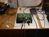
In many threads here I have expressed my doubts on accuracy of amplifier circuit simulations, especially in two points – very low harmonic distortions <0.001% and feedback (loopgain) unconditional stability. Based on my long, decades lasting experience in designing, building and testing power amplifiers I am declaring that transistor models available with freely distributed simulators like LTspice and others are not accurate enough to simulate neither very low levels of harmonic distortions, nor stability issues with complex load at frequencies >1MHz. I am going to prove my statements on the examples of two real world amplifier samples. And this will be also related to methods of frequency compensation of feedback amplifiers, based on Bode plots loopgain simulations.

Two amplifier samples will be analyzed, one with an old-school dominant-pole compensation, the other with more sophisticated TPC compensation, that allows for more loopgain at higher frequencies, thus lower harmonic distortion at higher frequencies. The amplifiers will be analyzed not only for distortion, but also for stability with complex load and this stability will be compared to assumptions derived from loopgain simulations.

1. The amplifier with the dominant-pole compensation

The amplifier sample has been described here in the thread
https://www.diyaudio.com/community/...er-and-my-diy-mods-schematics-gerbers.406947/

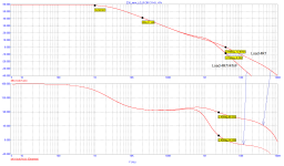
Loopgain simulation says that with a resistor load (4.7ohm) the phase margin at the point where the loopgain amplitude plot crosses 0dB, at 3.75MHz, is about 80°, which is enough for stable operation. The feedback factor (loopgain) at 20kHz is 41dB, which is the factor available for harmonic distortion reduction of this feedback amplifier, at 20kHz. At =<1kHz, the loopgain is 58dB.

Z30_new_LG_R.PNG

Now, when 47nF capacitor is added in parallel with 4R7 resistor, the loopgain amplitude plot crosses 0dB at 2.45MHz and the phase margin is now a mere 14°, so the amplifier should be close to instability.

Let's investigate the real amplifier sample, with a 10kHz square wave as an input signal, and both discussed loads.

Response into 4.7ohm resistor

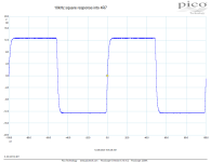
Z-30_10kHzsq_4R7.png

The response is nicely aperiodic, with no signs of instability. Exactly according to loopgain simulation.

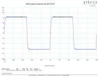
Response into 4.7ohm//47nF

Z-30_10kHzsq_4R7-47nF.png

47nF capacitor was added in parallel with the 4R7 resistor, however the square response remained unaffected. This is not in conformance with the simulated loopgain, which would suggest at least heavy ringing, with the simulated phase margin of only 14°.

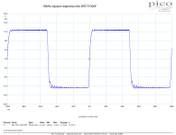
The amplifier is stable (in the real world) for wide range of capacitances, covering at least 0 – 100nF. First signs of compromised stability we can see with the 150nF capacitor // 4R7:

Z-30_10kHzsq_4R7-150nF.png

So, for this amplifier sample with dominant-pole compensation, the simulation was pesismistic compared to the real world results. Something does not fit, models?

2. The amplifier with TPC compensation

The amplifier sample has been described in the thread
https://www.diyaudio.com/community/threads/sab-class-ab-2x50w-4ohm-amplifier-with-smps.386169/

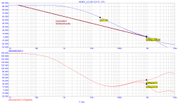
Loopgain simulation says that with a resistor load (4.7ohm) the phase margin at the point where the loopgain amplitude plot crosses 0dB, at 0.95MHz, is about 50°, which might be enough for stable operation. The feedback factor (loopgain) at 20kHz is 57dB, which is the factor available for harmonic distortion reduction of this feedback amplifier, at 20kHz. At =<1kHz, the loopgain is very high 93dB. Brown line in the graph would be a comparison to a dominant-pole compensation with the same unity gain frequency.

KENNY_LG_compareMiller.png

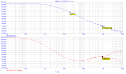
Now, when 47nF capacitor is added in parallel with 4R7 resistor, the loopgain amplitude plot crosses 0dB at almost same point near 0.95MHz and the phase margin is now a mere 30°, not much less than without the capacitor, and the amplifier should be still stable.

Another plot is with 15nF capacitor, and we can see that the phase margin is now 43°, definitely enough for the amplifier to be stable, at least in the simulation!

KENNY_LG_15n.png

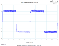
But how about the real world sample?? Alas, the amplifier's response oscillates with 4R7//15nF!

Kenny_10kHzsq_4R7-15nF.png

And increasing the capacitor to 47nF makes oscillations with much higher amplitude and the amplifier has suddenly blown the T5A fuse in the +rail of the power supply. But, due to very robust MJL21194/93 output pair, it has survived.

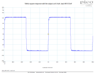
I inserted the 0.4uH output coil behind the amplifier's output ad now it was able to drive 4R7//33nF load with slight signs of oscillations only.

Kenny_10kHzsq_0.4uH+4R7-33nF.png

Test bench, load and output coil testbench.JPG

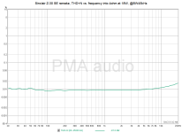
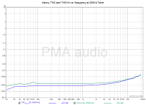
So, with the more sophisticated compensation scheme, we have got this improvement in THD+N vs. frequency at the expense of much worse amplifier stability, though the simulations did not suggest the stability worsening.

Z-30_thdn_frequency_BW45kHz.png Stepped THDfreq Kenny 20W.png

It is up to you to make a choice, if you prefer some inaudible improvement in THD+N, or an unconditional amplifier stability. And remember, do not forget to use the output coil with feedback amplifiers!

Just out of curiosity: could a multilayer board be substituted with several single-layer ones?

Hi friends, and happy 2024!

Yes I know it's silly. But so is my brain... I'm a bit into avoiding high-tech methods even for high tech products 🙄

Was wondering wether I could make a multilayered board out of the equivalent number of single-layered, self made ones?
You know, with this laser-printing, ironing onto the bare board-method, making one per layer, stack them, and accordingly connect them with a piece of wire...

At least, I hope this is good for a little smile or something...

:cheers:
david🙂
  • Like
Reactions: Ixnay

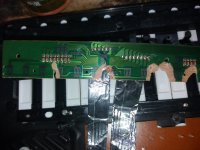
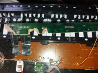
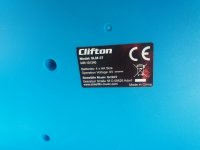
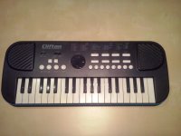
Key printboard schematic for Clifton SLM-37 = Sheffield SLM-37

Hi !
Do anyone have a schematic or good picture of key printboard - Clifton SLM-37 = Sheffield SLM-37 ? Both have same internal configuration.
I received one broken, I would like to restore it but is difficult to imagine the originl wiring.
Thanks.

Attachments

  • orga Clifton SL-37-01.jpg
    orga Clifton SL-37-01.jpg
    253.9 KB · Views: 233
  • orga Clifton SL-37-02.jpg
    orga Clifton SL-37-02.jpg
    349.7 KB · Views: 230
  • orga Clifton SL-37-06.jpg
    orga Clifton SL-37-06.jpg
    454.1 KB · Views: 224
  • Orga pian Clifton SLM-37-A-00.jpg
    Orga pian Clifton SLM-37-A-00.jpg
    155.1 KB · Views: 218
  • Orga pian Clifton SLM-37-A-02.jpg
    Orga pian Clifton SLM-37-A-02.jpg
    154.3 KB · Views: 348
Projects by fanatics, for fanatics
Get answers and advice for everyone wanting to learn the art of audio.
Join the Community
507,672
Members
7,883,590
Messages

Filter

Forum Statistics

Threads
405,997
Messages
7,883,590
Members
507,672
Latest member
rooomn