Guys, hello.
Here is a story.
This amp is 12 years old now.
I tried to tune idle currents for this amp to be around 3-3.5mA (this voltage is indication of correct idle currents) on each channel. These values are specified in service manual (attached to this post).
Year ago I was able to do this, but it was very hard. Probably because original trimpots were very sensitive, lacking of control.
This tuning inproved sound quality a lot.
But now the amp sounding a bit dead. I read the idle currents values and they went to 5mV and 10mV on channels. So I tried configure the idle currents again but I can not do it any more.
So I decided to replace original trimpots with new (better version)
BOURNS - 3296Y-1-201LF - TRIMMER, 25 TURN 200R
And replacement went well.
And for the first time after replacement I even managed to configure the idle currents to 3.1mV on both channels.
But after couple of hours of listening on average volume the sound went bad again.
But what I see now is :
1) On one channel with trimpot on minimum resistance of 0.5ohm I have idle current is 5.4mV.
If I increase value resistance of trimpot, the idle current goes higher. So no way of getting of 3mV.
On average on this channel the resistance of trimpot is tightly connected with idle current value.
2) On other channel trimpot has value of 120ohm and idle current is configured on 5.4mV.
If I go to lower resistances, then for very long range of them I see no change in idle current, but then it starts to lowering to 4.5mV and then it drops down to 1.2mV. Then, if I go with higher resistances, then again for long time I dont' see any change in idle current and then it jumps up to 4-5mV. So I am not getting the desired 3mV. Such bad not linear behavior.
So, on this channel I see that resistance of trimpot is not very tightly connected with idle current value.
Why such issue can happen?
Do you think that transistors went bad?
If yes, then which once do you suspect?
There are three pairs of transistors on each channel (as I understand).
First pars is small (SMD), second is bigger (vertical PCB mount with small personal heatsink) and then comes the biggest one (Vertical PCB mount on huge heatsink).
But I don't understand (due to lack of experience) which pair is controlled by trimpot and which is not.
Please look on attached schema.
Trimpots have markings of VR103 and VR303.
I measured resistors that are installed in series with trimpots R432 and R232 and they have OK value (slightly above 500ohm, as per spec).
Also both R233 and R433 are fine.
Thanks a lot.
UPDATE from 15/02/2021
SUMMARY OF SOLUTION in my case (for people who does not want to read the whole thread):
The leaking elements were Zener diodes D322, D323, D122, D123.
After replacing them (with MMSZ5231BT1) I got full control on idle currents on both channels.
While replacing pay attention to orientation, see service manual for reference.
Important: don't heat the new Zener diodes for more then 10 seconds on 260C temperature.
260C is enough to solder new diodes in place.
Attachments
Last edited:
Well you are in the right place and you have tested the series resistors and replaced ( I take it --VR303 /VR103 ) but what about the actual "amplified diode " circuit ( a term for the BJT that adjusts the bias ) .
That --in your case is Q348 an SMD transistor , its either faulty or you have a bit of instability causing insipid HF oscillation replace C417 at the same time,that would be a start.
Its that BJT that controls the driver pair not the other way around.
That --in your case is Q348 an SMD transistor , its either faulty or you have a bit of instability causing insipid HF oscillation replace C417 at the same time,that would be a start.
Its that BJT that controls the driver pair not the other way around.
Well you are in the right place and you have tested the series resistors and replaced ( I take it --VR303 /VR103 ) but what about the actual "amplified diode " circuit ( a term for the BJT that adjusts the bias ) .
That --in your case is Q348 an SMD transistor , its either faulty or you have a bit of instability causing insipid HF oscillation replace C417 at the same time,that would be a start.
Its that BJT that controls the driver pair not the other way around.
Thank you very much!
Another detail that I missed is that I had some kind of surge in my apartment. And pair of Q348 and C417 are sitting between two mains of + -, so they could be fried a bit.
Will start with such replacement and update here.
Other opinions and ideas are welcomed too!
Hello, guys.
Update.
Some additional diagnostics.
With time of working (4-5 hours) idle currents on both channels stabilized on value of 4.2mV. So they are kind of symmetric now, but still are not ideally set to 3-3.5mV as service manual suggests.
Both VR103 and VR303 resistors are set on its lowest value.
When I rotate VR103 and VR303 to increase their values I don't see any change in idle current for some number of rotations (looks like changing their values from 1 ohm to lets say 30 ohms has no effect on idle current at all!). Only after some few rotations the idle current values start to rise.
Any way I am not able to bring idle currents lower then 4.2 mV.
I tried to go with suggestion of duncan2 and I replaced both transistor Q348 and capacitor c417.
But this change did absolutely no effect.
I have some suggestion on what happened. It can be that during the surge some high level current went through gentle transistors (Q347 and Q347 on diagram) and now they both are just not able to support low idle currents at all.
Does this suggestion has some true in it?
If yes, then maybe next step should be go and replace these transistors?
Thanks a lot.
just chiming in here: have you checked or just replaced any of the e-caps in the power amp stage?
Just saying NAD equates to crappy e-cap brand selection and poor construction. I know, I have several NAD amps (which I absolutely love now) including a C325BEE (older version of C326BEE).
But it takes some work to bring these units back to health.
I would suggest looking at C160, C161, C162, C163 (and the C36x right channel as well). Either check'em with an ESR meter or just replace if odd-ball brands. And if 85C change to 105C temp rating.
just chiming in here: have you checked or just replaced any of the e-caps in the power amp stage?
Just saying NAD equates to crappy e-cap brand selection and poor construction. I know, I have several NAD amps (which I absolutely love now) including a C325BEE (older version of C326BEE).
But it takes some work to bring these units back to health.
I would suggest looking at C160, C161, C162, C163 (and the C36x right channel as well). Either check'em with an ESR meter or just replace if odd-ball brands. And if 85C change to 105C temp rating.
Thanks.
No, I did not touch any ecaps in power amp stage. I did not check them, since amp is working fine on very high volumes.
Do you think that they are related to idle current problem?
Do you think that C160, C161, C162, C163 can have influence on idle current? In which way exactly?
Do you think that C160, C161, C162, C163 can have influence on idle current? In which way exactly?
If these e-caps are becoming faulty they start to act more like resistors than capacitors (instead of blocking DC currents they start allowing DC currents to flow).
These e-caps I pointed out are after the predriver/differential stage and in the driver and bias stages. So I do think they can and will affect the power amp devices.
OK, here are more details about the amp.
Last time I tuned it I se 4.2mV on both channels. Listened for some hour then turned it off and did not turn it on for like month or two.
Before replacing capacitors you offered to replace, I measured idle current again and saw it somehow became 3.2mV on both channels!
Looks like something there is changing with times, affecting idle currents.
OK, I replaced all capacitors that you offered:
C160, C161, C162, C163, C360, C361, C362, C363.
All are from Nichicon UKA and UKZ.
Original capacitors that were installed were relatively good in terms of ESR and capacitance.
I don't really know how to measure the leakage current of capacitor yet
")
Both channels were tunable right after replacement. I set them both to 3.3mV and run the amp for like 2 hours of medium high volume.
Sound was pretty good!
After the run I measured idle currents again and saw that both channels went out of tune to 5mv and 6mv.
Now the situation is that I can still tune one channel (can tune from 1mv and higher any value, very fine precision) and other channel can not go lower then 4mV.
Another (probable) issue that I saw during replacement work.
I run the amp on average to high volume.
I see that heat radiators in preamp section are running hot, but touchable.
But in amp section something strange is going on.
I see that heat radiators of Q342, Q344, Q142, Q144 (and U104) are pretty hot. I can touch them, but can not hold the hand on them.
I would say that they are not normally hot.
Also when I look on SMD side I see some yellow burn in color in amp part.
But in preamp area I see similar yellow color too.
The heat radiators of Q346, Q350, Q146, Q350 are hardly warm.
Also the huge radiator for 4 main transistors stays pretty cold.
But when I put my face over the huge radiator I feel warm air coming through it, so I guess these main 4 are working.
But its not clear to me why to put such huge radiator on them.
Looks like from power amp section only Q342, Q344, Q142, Q144 are working very hard. And rest of transistors are pretty stale.
With all that I get pretty good sound and bass.
My guess is that there is something wrong around Q342, Q344, Q142, Q144.
Any ideas to try here?
Last edited:
I wanted to see what is the current that runs through Q342 (https://www.mouser.com/datasheet/2/149/ksa1220-300747.pdf) when amp is turned on and idle, with no inputs (this is the mode to set idle currents).
And I saw that on R441 (SMD RES 15 OHM 5% 1/16W 0603) I get 0.65V, this means that through Q342 I have current of 43mA.
And this is the situation for 3 other transistors too: Q344, Q142, Q144.
In comparison to Q350 (transistors that don't get hot) - there we have 35mA.
When I played with measurements I burned R441 down some how Probably shorted it to 46V and it stopped to work (showed me infinite resistance) and sound on right channel was gone
I hopelessly tried to find such SMD resistor on scrap boards that I brought from trash, but no luck. I had only 10 ohms resistors like this.
But I found one 10 ohm radial resistor 1W and 5 ohm radial resistor 1W.
I put them in series instead of R411 Looks ugly, but works, sound at right channel is back.
But now I measure only 0.45 V on R411! Which gives me fair 3mA idle current on Q342.
Its heat radiator became cooler relatively to heat radiators of Q344, Q142, Q144 which still run with 43mA idle currents.
I don't hear any impact on sound by now, but I understand something is wrong with right channel
Will find proper SMD resistor, will see what idle current I will get with proper transistor.
And I saw that on R441 (SMD RES 15 OHM 5% 1/16W 0603) I get 0.65V, this means that through Q342 I have current of 43mA.
And this is the situation for 3 other transistors too: Q344, Q142, Q144.
In comparison to Q350 (transistors that don't get hot) - there we have 35mA.
When I played with measurements I burned R441 down some how
Probably shorted it to 46V and it stopped to work (showed me infinite resistance) and sound on right channel was gone I hopelessly tried to find such SMD resistor on scrap boards that I brought from trash, but no luck. I had only 10 ohms resistors like this.
But I found one 10 ohm radial resistor 1W and 5 ohm radial resistor 1W.
I put them in series instead of R411
Looks ugly, but works, sound at right channel is back.But now I measure only 0.45 V on R411! Which gives me fair 3mA idle current on Q342.
Its heat radiator became cooler relatively to heat radiators of Q344, Q142, Q144 which still run with 43mA idle currents.
I don't hear any impact on sound by now, but I understand something is wrong with right channel
Will find proper SMD resistor, will see what idle current I will get with proper transistor.
Thanks for reply.What is "sound" issue?
Distortion at loud volumes?
General noise with no input?
Any o-scope visuals on the output?
Well, BEFORE I made the short problem it was no issue with sound
It was problem of setting idle current properly (original one).
And other issue (as I thought) was that Q342, Q344, Q142, Q144 were running very hot.
AFTER the short problem (now) I still have all previous problems and in addition:
1) Right channel is heavily distorted on medium to high levels.
Sounds sometimes just disappears when some heavy bass note. Then it comes back.
All this with serious cracks and whistles.
2) One of main transistors Q345 started to get hot, heating seriously the huge heat radiator (that is shared between 4 transistors like Q345).
From tools I have only multi meter and cheap ESR meter.
What I did by now:
I took out the C361 and C362. Both are new Nichicon UKA capacitors.
C361 showed high esr and I replaced it. C362 was fine. Sound improved a bit.
My thoughts as I understand.
What I did is that I shorted the emitter and collector of Q342 and this lead to very high current that burned the R441 that lead to to sound on right channel. The amp went into protection, saving me from further damage.
I replaced the R441 and sound got back but distorted.
I will try to look what else got burned with this high current. Maybe some other capacitors.
Too bad I have not much experience, but I will get some during the work
I try to measure resistance in different points on both channels comparing them to get direction.
In this way I found that C361 and C362 are probably dead.
Some measurements that I did.
When amplifier is off I measure resistance on contacts of C361 is 27 Ohm and 2k ohm on switch of probes.
In contrast to left channel I measure Mega ohms and Kilo ohms values.
C361 sits in parallel with D322 diode (probably is dead/shorted too together with D323).
The idle current on right channel that I measured when amplifier is on is 47mA I guess that's why Q145 is so hot.
When amplifier is off I measure resistance on contacts of C361 is 27 Ohm and 2k ohm on switch of probes.
In contrast to left channel I measure Mega ohms and Kilo ohms values.
C361 sits in parallel with D322 diode (probably is dead/shorted too together with D323).
The idle current on right channel that I measured when amplifier is on is 47mA
I guess that's why Q145 is so hot.Definitely on a good track here, the zeners.
So is Q342 still OK after the mistaken short? Q344 too since it's part of the current flow?
Might as well check those small signal diodes (1N4148) D324, D325, D326, D327 that hold the base node at a 2X diode voltage level.
Just covering all bases.
So is Q342 still OK after the mistaken short? Q344 too since it's part of the current flow?
Might as well check those small signal diodes (1N4148) D324, D325, D326, D327 that hold the base node at a 2X diode voltage level.
Just covering all bases.
Definitely on a good track here, the zeners.
So is Q342 still OK after the mistaken short? Q344 too since it's part of the current flow?
Might as well check those small signal diodes (1N4148) D324, D325, D326, D327 that hold the base node at a 2X diode voltage level.
Just covering all bases.
Thanks
I think both Q344 and Q342 are working (because I can hear the sound), but not clear if they completely OK. Maybe will replace them.
If I understand right, then short on Q342 just built a 0 ohms path for current to flow and skip the transistor at all.
So it should not take any damage.
I will replace :
1) Zener diodes D322, D323
2) small signal diodes D324, D325, D326, D327
3) Resistors R441, R435
4) All electrolytic capacitors C360, C361, C362, C363
Then will look if things will get to normal.
I try to understand why idle current through Q344 and Q342 is relatively high (causing them to be heated considerably.
It was high before the short and before any of my modifications.
Maybe it is like that by design?
Or maybe because some components (like small signal diodes) are worn out with time?
Will check temperatures after my replacements.
Do you have some idea on how can I lower the idle current through Q344 and Q342?
I mean some mod of replacing components to ones with different values?
Last edited:
Well should have asked this 1st: are your power supply voltages on target?
+/- 46V supply
+/- 37V supply
+/- 18V supply
As for why the currents are high through Q344 + Q342; the zeners + 1N4148 diode could be why. If the zeners are not holding their appropriate breakdown 5V voltage and/or the pair of 1N4148 diodes aren't dropping ~1.4V then the transistors could be conducting hard. These diodes are setting up voltage references so if they are not correct it will upset the circuit. Of course this all stems from good power supply source.
Continuing on other components, have you checked resistor values in these driver and pre-driver stages...are the resistors in spec?
Last question here; what about DC offset? Have you measured this?
+/- 46V supply
+/- 37V supply
+/- 18V supply
As for why the currents are high through Q344 + Q342; the zeners + 1N4148 diode could be why. If the zeners are not holding their appropriate breakdown 5V voltage and/or the pair of 1N4148 diodes aren't dropping ~1.4V then the transistors could be conducting hard. These diodes are setting up voltage references so if they are not correct it will upset the circuit. Of course this all stems from good power supply source.
Continuing on other components, have you checked resistor values in these driver and pre-driver stages...are the resistors in spec?
Last question here
; what about DC offset? Have you measured this?Thanks for the ideas.
1) I will check the voltages that I get from power supply.
2) I don't really know now what are "driver and pre-driver stages".
Can you point me to what exact resistors should I look?
3) What do you mean by "DC offset"? The DC on speakers outputs of amplifier?
1) I will check the voltages that I get from power supply.
2) I don't really know now what are "driver and pre-driver stages".
Can you point me to what exact resistors should I look?
3) What do you mean by "DC offset"? The DC on speakers outputs of amplifier?
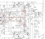
I attached a pic of what I consider pre-driver, driver and poweramp stages.
I mentioned the ISC circuit, this is a NAD thing, suppose to monitor (sense) load impedance changes and adjust the power supply accordingly.
There is an adjustment for this in the manual.
As for resistors, I'd check all in poweramp and driver stages. Working from back to front (poweramp to driver). With no power you can
get "ballpark" ohmic checks in-circuit with a DMM. If some resistor really measures extremely off then you may have to un-solder one leg for an accurate reading. And I check diodes and transistors (diode check) as well.
DC offset; yes measured on the speaker terminals (no speakers attached, no input [usually selector on AUX with no connection]), all tone controls flat, volume zero and after 5 minutes warmup at least. DMM on DC millivolt setting connect to speaker terminals, measure one channel then the other.
0-50mV is good, >50mV troublesome, >100mV not good.
Attachments
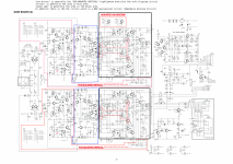
You have both components and copper (SMD) sides diagrams in service manual in first post.Can you take pictures of both sides of the main board?
I did not know that NAD used a lot of SMD components and I can't find any decent images on the 'net so I'm just cuious.
I will take pictures and post here once I get to to the work again.
For now I packed everything and put it into secret place, so my woman will not see it
)- Home
- Amplifiers
- Solid State
- NAD C326bee idle currents problem