Hi All,
I have a question regarding resistors values that are in between a digital filter and the Dac chip I2S input.
I've noticed that the resistors values are different in every CD player or Dac, some use 300r, some have 1K, some don't have any resistors at all.
I would like to know please why there is a difference and how the resistors value affects the Dac ?
Thanks
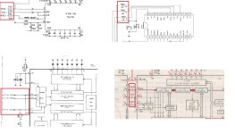
Attachments
You can view those resistors as a type of termination. Basically, their purpose in life is to ensure a clean digital signal without excessive ringing.
They will likely have to be tailored to the circuit as the cleanliness of the digital signals depends on the parasitics of the board layout and digital I/Os.
1 kΩ sounds way excessive unless someone is trying to make a crappy level translator from 5 V to 3.3 V. I'd think that a few tens of ohm would be plenty to tame the transient response of those I/Os.
Tom
They can also be to reduce EMI to be able pass EMC testing. If the driving chip generates fast edges resistance will slow them down. However 1k is large and will probably affect jitter on the clock signals.
I don't know the case of PCM63P, but the TDA1541 has current inputs. The resistors convert the I2S signal voltages to input currents. If you drive the DAC with TTL voltage level, the inputs are overloaded and spikes appear on the analog output. I think this is referred as "ground bounce".
What do you mean?, but the TDA1541 has current inputs.
From TDA1541/1541A datasheets:
All digital inputs are TTL compatible
input current pins (1, 2, 3 and 4)
-IiL digital inputs LOW VI = 0.8 V - - 0.4 mA
IiH digital inputs HIGH VI = 2.0 V - - 20 uA
- Home
- Source & Line
- Digital Source
- I2S lines resistors