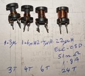
I've had success in making two valve amps with global feedback unconditionally stable, compared to original operation showing unstable operation with certain capacitance only loading. The technique used follows on from Patrick Turner's use in two restorations (a Dynaco MkIV and a 100W UL monobloc). Sadly I didn't get time to discuss this topic with Patrick, but was pleased to follow his lead and test the concept in a Williamson amp last year, and just recently in an Encel X1212 stereo 12+12W valve amp from mid 1960's (aka a Star SA-30 from Japan).
The technique inserts a small low-value inductance in series with the normal voltage feedback signal, such that load current passes through the inductor, as shown in the example schematic below. The inductor used was a modified 22uH open-wound ferrite slug type, with turns removed to get down to circa 1-3uH. I compared stability performance in the Williamson, with results in https://dalmura.com.au/static/Williamson output transformer measurements.pdf.
The Encel amp was unstable with certain capacitance only loading, but otherwise stable with its 13dB feedback as it uses a heavy step network on the input stage to roll off gain. I wasn't able to improve on the stability performance with simple capacitor compensation across the feedback resistor, but didn't go further down that path. Instead I deployed a 2uH inductor and was able to achieve unconditional stability even after removing the step network (which was my aim if practical).
The inductor I used was quite small, and very simple to retrofit in the Encel, and in some amps it may be quite easy to implement. So I can recommend it when squarewave testing is available to check stability.
Ciao, Tim
Attachments
Last edited:
Good work.
Interesting, Csz & Rsz on secondary does appear in some designs (Radford), but I had also thought of using lossy ferrite beads or med/low u toroids over each o/p secondary wire (8 wire secondary) and alter the feedback/ ground returns, if a little tedious to do. Things get a little awkward if a sub optimal speaker cable is also used which is also parasitic (as are any crossovers).
I shall try the ferrite idea again on my 150W amp 18 section output tranny which is wound to a Williamson spec. I had long suspected the secondary parasitics were the creator of much resonance L&C´s that is if the winding isn´t wound optimally, but one has to go about these tests very carefully. There is also the UL anode/screen grid RC combination to fog the equations. Good transformer manufacturers know too well that the 8 ohm winding which is really compromised, is made by a couple of parallel and two series windings which isn´t optimal, nor is the-all-one-winding 0-4-8-15 ohm with high tap leakage inductance.
With an output transformer on the bench, one an easily check for multi secondary winding equality/purity by putting through a khz squarewave with appropriate load terminations and altering the series/parallel combination to get the best waveform and noting. Most output transformers will show irregularities on a CRO. Output transformer manufacturers do not provide optimum permutation of various secondary windings. They will just note ABCD. The rest is down to us !
I notice too that many transformer houses also impregnate the windings after being completed. This is a MISTAKE as the dielectric capacitance increases when one is trying damnest to avoid it ! Good old Kellogs interleaving paper and maybe just an end bobbin varnish seal is all and no more.
BB
From what I can see, the common technique for 'confirming' unconditional stability in valve amps has over the decades tended towards testing at no load, and with a small range of capacitor only values. That seems reasonable, but I'd expect there may be the rare situation of a particular load where a particular amp could go unstable, so caveat emptor. During the 1950's, the thousands of Heathkit Williamson's showed up enough field reports that by 1955 the W-5M amp included a 'tweeter saver' - aka an RC zobel network on the load terminals. And I've come across speaker crossovers with the same form of zobel network integrated.
When I was testing the Williamson amp, I tried a few inductor parts/combinations to see what difference there was. I had some slip-on ferrite tubes of two lengths and a leaded ferrite tube - they were of a ferrite type designed for emi dampening - as an example, the leaded part had an inductance of about 1.0uH, which increased to about 1.5uH with a short length bead over one lead, when measured with soundcard/REW impedance jig out at 30-60kHz, and checked with LCR meter at 10kHz. The emi type ferrite data appear to present stable impedance out to 1MHz, as they are aimed at low MHz suppression, so should be consistent at the likely unstable resonant conditions of most valve amps (ie. 100-500kHz), and the current levels likely to be experienced.
The particular output transformer I was testing with in the Williamson had a dominant squarewave ring out at circa 200kHz, which was convenient to use as an indicator of stability margin, and for comparing different combinations of feedback compensation. That allowed a good indication of an appropriate value of inductance to use (given I was able to iteratively test with the same base Panasonic ELC-08D220 part but with different numbers of turns). In contrast, the Encel amp's output transformer appeared to present quite a steady gain and phase change out to resonance (circa 160kHz) with no convenient squarewave ringing to use, up until unstable operation. A 1955 report illustrates the variety of higher frequency resonant responses that can be expected from even 'good' output transformers - https://dalmura.com.au/static/NRL report 4136.pdf .
Patrick Turner (RIP) made and tested quite a few output transformers and I had a few email chats with him on the topic of winding construction. He settled on a very manually intensive method of applying floor varnish to each layer of winding to provide a stable environment with a suitable level of distributed capacitance to push resonances out beyond 200kHz with well damped characteristics. In summary, it was the mix of low distributed leakage, and just enough distributed capacitance (from the varnish dielectric), that gave the total result - ie. not what may be initially assumed to be the better technique of lowest capacitance. To his credit, he put a lot of effort and leg-work into understanding and improving this topic, and even started from academic 'scratch'.
Over the years some of us burnt much midnight oil on this; but now with darker nights in the N Hemi, more time devoted to the in-house bench. To the amp builder this parasitic stuff must be a bewildering foggy subject hard to grasp. There is good advice towards an amp design/kit circuit with an output transformer that offers proven performance, given that winding houses are gradually losing their experienced staff, some put-in decades of loyal experience. The tricky highly compromised designs fading away to a winding product perhaps having only a few sectioned windings, with all it´s parasitic issues.
Fortunately, my 6 decades experience in switchmode and power electronics, (soon another tube behemoth will appear, a KT88/90 stereo 400W P-PP amp with a SMPs B+) such experience can immediately spot parasitic problems. As P.Turner found out, putting ferrite tubes or sim, on relevant output wires is a normal tactic for EMI suppression that in my case one can "kill two parasitic birds with one stone". Any fundamental and /or charge switching harmonics are also dealt with. Knowledge of ferrite /material properties from various vendors is crucial.
In 1968 as finishing UniI I revert to my hazily scribbled midnight notes regarding the connection optimization of a p-p UL output transformer with identical multiple secondary windings. (I´ll keep the math and complex waveform analysis out of this). At that time, I was curious about the Quad amp cathode tertiary feedback arrangement. Was that transformer winding optimized over the stray parasitics? The McIntosh designs of bifiliar winding the entire lump was a solution so long breakdown didn´t occur. I never owned a Quad amp but serviced a few in my time. Here in pic is a typical label denoting secondary arrangements of a good quality transformer. However, read on.

More recent times, 15 yrs ago I bespoked two custom 18 section Williamson design o/p trannies to an old time UK winding house who had the original interwinding configuration details. After receiving, and some testing I soon found out that one should never take for granted the identical multiple secondary winding configurations that winding houses provide for load permutations. The transformers as they stand with suggested connections put into a circuit would offer excellent results that maybe no-one would spot performance differences; but get the squarewave performance optimized, much inter-swapping of secondary permutation eventually arrived with bandwidth improvements with minimal ringing. (See pic)

There were secondary configurations that could make a mess of the square wave, contradicting the series R/C´s and phase corrections in amp circuits. So complex L&C´ parasitics, even by a slight winding orientation misplacement is enough to manifest as Morgan Jones found out. The higher the frequency and rise-time, the more irregularities one spots. There is another; that RC combination often used between the UL screen tap to anode. Most designs use 1K+1nF, but values also creates subtle differences in the rise and fall squarewave ramp. More work to be done on this.
Also on hand, I had two similar transformers from another manufacturer (7 sectioned designs from Sowter) so the differences could be compared. I decided to examine/ optimize the secondary configuration before all was bolted to the chassis. After a little testing I found the Sowter had higher winding resistances and capacitances. I strongly suspect their designs are computer optimized designed whereas the more intensively hand-made 18 sectioned Majestic used the backdrop of the old Williamson details.

Each output transformer weighs 12 kg. With 2KA-A, 43%UL taps, each secondary winding is rated over 200W. The large core rated for distortion around 1.5% at 15Hz; that implies the midband could easily handle 500W before other issues arise. With the large bobbin there is a fair amount of wire so mean LPT (length per turn) tendency towards a high capacitive interlayer exposure, so the parasitics and eventual upper frequency curtailment were a prescribed certainty. A knowledgeable winding house can compromise much interwinding conflicts and advise on Si-Iron grades; provide expected power bandwidth, cutoff freq; and distortion prediction. Langford-Smith Radiotron Handbook mentions all these parameters can be theoretically worked out.
My conclusion to the budding P_P amp builder, take note, “don´t bite more than one can chew”.
BB
Fortunately, my 6 decades experience in switchmode and power electronics, (soon another tube behemoth will appear, a KT88/90 stereo 400W P-PP amp with a SMPs B+) such experience can immediately spot parasitic problems. As P.Turner found out, putting ferrite tubes or sim, on relevant output wires is a normal tactic for EMI suppression that in my case one can "kill two parasitic birds with one stone". Any fundamental and /or charge switching harmonics are also dealt with. Knowledge of ferrite /material properties from various vendors is crucial.
In 1968 as finishing UniI I revert to my hazily scribbled midnight notes regarding the connection optimization of a p-p UL output transformer with identical multiple secondary windings. (I´ll keep the math and complex waveform analysis out of this). At that time, I was curious about the Quad amp cathode tertiary feedback arrangement. Was that transformer winding optimized over the stray parasitics? The McIntosh designs of bifiliar winding the entire lump was a solution so long breakdown didn´t occur. I never owned a Quad amp but serviced a few in my time. Here in pic is a typical label denoting secondary arrangements of a good quality transformer. However, read on.
More recent times, 15 yrs ago I bespoked two custom 18 section Williamson design o/p trannies to an old time UK winding house who had the original interwinding configuration details. After receiving, and some testing I soon found out that one should never take for granted the identical multiple secondary winding configurations that winding houses provide for load permutations. The transformers as they stand with suggested connections put into a circuit would offer excellent results that maybe no-one would spot performance differences; but get the squarewave performance optimized, much inter-swapping of secondary permutation eventually arrived with bandwidth improvements with minimal ringing. (See pic)
There were secondary configurations that could make a mess of the square wave, contradicting the series R/C´s and phase corrections in amp circuits. So complex L&C´ parasitics, even by a slight winding orientation misplacement is enough to manifest as Morgan Jones found out. The higher the frequency and rise-time, the more irregularities one spots. There is another; that RC combination often used between the UL screen tap to anode. Most designs use 1K+1nF, but values also creates subtle differences in the rise and fall squarewave ramp. More work to be done on this.
Also on hand, I had two similar transformers from another manufacturer (7 sectioned designs from Sowter) so the differences could be compared. I decided to examine/ optimize the secondary configuration before all was bolted to the chassis. After a little testing I found the Sowter had higher winding resistances and capacitances. I strongly suspect their designs are computer optimized designed whereas the more intensively hand-made 18 sectioned Majestic used the backdrop of the old Williamson details.
Each output transformer weighs 12 kg. With 2KA-A, 43%UL taps, each secondary winding is rated over 200W. The large core rated for distortion around 1.5% at 15Hz; that implies the midband could easily handle 500W before other issues arise. With the large bobbin there is a fair amount of wire so mean LPT (length per turn) tendency towards a high capacitive interlayer exposure, so the parasitics and eventual upper frequency curtailment were a prescribed certainty. A knowledgeable winding house can compromise much interwinding conflicts and advise on Si-Iron grades; provide expected power bandwidth, cutoff freq; and distortion prediction. Langford-Smith Radiotron Handbook mentions all these parameters can be theoretically worked out.
My conclusion to the budding P_P amp builder, take note, “don´t bite more than one can chew”.
BB
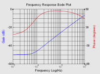
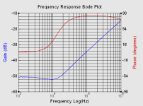
To add some measurement detail related to the feedback inductor part, there are six gain-phase plots below for a passive R-L network attenuator fed by a signal generator, based on a Picoscope 4224A and FRA4 software. The gain (attenuation) is the signal across the test inductor L, with the input signal level presented to a 10 ohm resistor R. In general, the impedance of the inductor below circa 10kHz is negligible and resistive, and so there is only a low voltage signal with close to zero phase shift across the inductor, as shown by the attenuation level. Most of the plots show the inductors exhibiting 90 deg phase shift from about 10kHz to a few hundred kHz, and a 20dB/decade change in gain, which is likely what is required to provide a stable feedback signal in the frequency range of interest.
The 4T part is shown in the photo in post #1 as 1.6uH, as originally estimated by modelling in an REW/soundcard impedance jig. That estimate appears to be somewhat high, as the attached attenuator plot for that part indicates an inductance of 0.84uH, and a turns-ratio estimate of the original 22uH part (with 24.5 turns) would suggest a 0.74uH value with 4.5 turns.
The plots of the ferrite bead/tube parts indicate inductances of 0.6-0.66uH, where 5mm and 6mm refers to the length of the ferrite bead. The ferrite material was not known for each of those parts, although they were for general emi suppression use.
For contrast, one of those plots is of a suitably low inductance smt part ( 4.7uH CTMC1812) I had on hand indicates that various part technologies may not be suitable as the part becomes resistive after a few hundred kHz. Another plot is for another 1812 size smt part applicable to EMI suppression, with a 300mA 70R 100MHz rating, that appears to present about 0.13uH.
Attachments
-
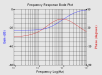 10R 4u7 ctmc1812 inductor attenuator.png12.4 KB · Views: 75
 -
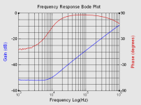 10R 6mm fixed bead attenuator.png13.2 KB · Views: 86
 -
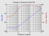 10R 5mm slip bead attenuator.png13.2 KB · Views: 67
 -
 10R 4T inductor attenuator.png13.1 KB · Views: 78
 -
 10R 2T inductor attenuator.png15.9 KB · Views: 67
 -
 10R 1812 300mA 70R 100MHz emi inductor attenuator.png12.5 KB · Views: 70
