Hi all,
I've designed a biradial waveguide for my tweeter in CAD (linear horizontal expansion and exponential vertical expansion). Looks great, although I can't quite get my head around how I would could the ideal crossover frequency for it. I've analysed it in AKABAK (using youtube tutorials) but not quite sure what I'm looking out for. Tried searching google but the results I get aren't quite what I'm trying to ask - maybe I'm wording my problem wrong.
I'm trying to optimise a wide directionality for an open sound.
Fairly new to DIY speaker design and building, and very new here so apologies in advance if I've posted this in the wrong area.
Any nudge in the right direction would really help.
Polar measurements can help you determine the place it reaches the wanted directivity. You'd also want to see that it performs consistently in the intended passband.
The catch for an asymmetrical device is that it may only radiate axisymmetrically (round) at one frequency, which kind of forces the woofer and crossover choices.
The catch for an asymmetrical device is that it may only radiate axisymmetrically (round) at one frequency, which kind of forces the woofer and crossover choices.
This thread would be a good nudge:Hi all,
Looks great, although I can't quite get my head around how I would could the ideal crossover frequency for it.
Any nudge in the right direction would really help.
https://www.diyaudio.com/community/threads/acoustic-horn-design-the-easy-way-ath4.338806/
Semantically, a bi-radial design using an exponential expansion in either direction would be considered a horn, rather than a waveguide.
What would or could be the ideal crossover point for a horn is dependent on each driver used in the system, their individual excursion limited output potential, the SPL desired/required, what you consider "wide", and how high of a frequency you want to be that width.
Generally, over 90 degrees at -6dB horizontal dispersion compared to on axis is considered "wide", requiring the horn throat to be no more than about a wavelength wide at the highest frequency that width is desired.
I was in the same boat several months ago. I don't know how to use AKABAK but I simulated my drivers/enclosure in ABEC then exported FRD files to simulate the crossovers in VituixCAD. Alternatively, you can physically build and measure the drivers in REW or other measurement software and import those files into VituixCAD. Once you have your FRD files in VituixCAD you can simulate different crossovers. If you physically build the speaker you can also listen to the different crossover options by exporting files from VituixCAD into a program such as Equalizer APO (Windows) and individually amplifying each driver via an audio interface or home theater receiver connected by your PC outputs. That's the method that worked out best for me personally but it is far from the only method available.
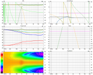
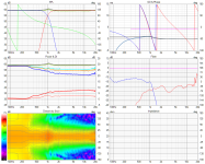
First image is from VituixCAD from FRD files simulated in ABEC. Second image is from real measurements taken in REW and imported into VituixCAD. The REW measurements are wrong because I measured in 10 degree increments rather than 5 degree increments that VituixCAD instructions require when you measure speakers with higher directivity (waveguides).
Simulated vs REW measurements
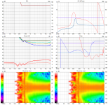
To give you a basic idea of where you might look for places to cross, here are the independent measurements of my woofer and tweeter flattened on-axis.
Tweeter vs Woofer
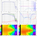
I'm still in learning phase so I bet other people could show you much better VituixCAD simulations to show you what to look for. Which reminds me of something. If you go to the trouble of learning VituixCAD and importing your measurements it is an excellent way to receive help with your speakers because you can show your images like I just did. ABEC simulation isn't necessary but it helped me discover my measurements were bad. Simulation also helped me rapidly iterate designs.
First image is from VituixCAD from FRD files simulated in ABEC. Second image is from real measurements taken in REW and imported into VituixCAD. The REW measurements are wrong because I measured in 10 degree increments rather than 5 degree increments that VituixCAD instructions require when you measure speakers with higher directivity (waveguides).
Simulated vs REW measurements


To give you a basic idea of where you might look for places to cross, here are the independent measurements of my woofer and tweeter flattened on-axis.
Tweeter vs Woofer


I'm still in learning phase so I bet other people could show you much better VituixCAD simulations to show you what to look for. Which reminds me of something. If you go to the trouble of learning VituixCAD and importing your measurements it is an excellent way to receive help with your speakers because you can show your images like I just did. ABEC simulation isn't necessary but it helped me discover my measurements were bad. Simulation also helped me rapidly iterate designs.
It appears from observation that Vituixcad interpolates the intervening angles. Some of the internals of Vituixcad are not clear, so I'm not sure, but I'm inclined to disagree with your usage of the word 'wrong', when lower resolution might be a more fitting way to describe it.The REW measurements are wrong because I measured in 10 degree increments rather than 5 degree increments that VituixCAD instructions require
You're right. I didn't check the woofer, only waveguide portion. Here's a post in the ATH thread showing the difference between using 5 degree vs 10 degree vs the simulation. Albeit, with different microphones. I still haven't confirmed with my XLR microphone but now that I think about it I should probably simulate the waveguide using 10 degree increments rather than 5 and see what happens in VituixCAD.
https://www.diyaudio.com/community/...-design-the-easy-way-ath4.338806/post-7503817
https://www.diyaudio.com/community/...-design-the-easy-way-ath4.338806/post-7503817
I just imported a set of 10 degree increments from the simulation (deleted the FRD files between every 10 degrees and then imported them as a separate driver). There's a little bit of difference but not much compared to the difference from my two sets of REW measurements. Of course, my two REW measurements are a lot more ragged. I guess the next step would be to take my original 5 degree REW measurements and delete every other measurement to see what happens when I only supply VituixCAD with 10 degrees from that set.
Simulations: 2.5 degree vs 10 degree
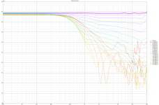
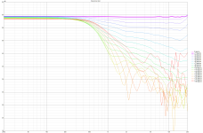
Simulations: 2.5 degree vs 10 degree


I didn't import my 5 degree measurements yet but I just read this post from HiFi Jim where he built a draft enclosure in rigid foam. Easy to experiment with angles that are difficult to cut in wood or quickly resize an enclosure you want to match to your waveguide.
https://www.diyaudio.com/community/threads/purifi-waveguide-project.394174/post-7226611
https://www.diyaudio.com/community/threads/purifi-waveguide-project.394174/post-7226611
Hey, apologies for the delayed response. Did you start learning ABEC from scratch or do you have a background in acoustics? Trying to teach myself how to use these programmes as I'm getting into changing the components on the speakers I built.I was in the same boat several months ago. I don't know how to use AKABAK but I simulated my drivers/enclosure in ABEC then exported FRD files to simulate the crossovers in VituixCAD.
This is really useful as you've done exactly what I'm trying to do.
Did you ever remeasure at 5 degree increments and if so did the increase in resolution change anything significant? Would you say your FEA results are better to use when deciding to cross or real world results as its important to factor the room?The REW measurements are wrong because I measured in 10 degree increments rather than 5 degree increments that VituixCAD instructions require when you measure speakers with higher directivity (waveguides).
Thank you thats helpful to understand! Will give a read.This thread would be a good nudge:
https://www.diyaudio.com/community/threads/acoustic-horn-design-the-easy-way-ath4.338806/
Semantically, a bi-radial design using an exponential expansion in either direction would be considered a horn, rather than a waveguide.
What would or could be the ideal crossover point for a horn is dependent on each driver used in the system, their individual excursion limited output potential, the SPL desired/required, what you consider "wide", and how high of a frequency you want to be that width.
Generally, over 90 degrees at -6dB horizontal dispersion compared to on axis is considered "wide", requiring the horn throat to be no more than about a wavelength wide at the highest frequency that width is desired.
- Home
- Loudspeakers
- Multi-Way
- What is the method for determining optimal crossover frequency for waveguide I've designed
