Rubber-coated cloth surround cracking

Hello everyone. I have a fairly old but good subwoofer, it's the old Hertz ML3800: https://www.rgsound.it/prodotti/atch/pdf_ml3800.pdf
The woofer sounds great, and I would like to use it to make a sealed subwoofer for my car with Linkwitz transform.

However this speaker has what looks like a rubber coated fabric surround and it seems the rubber coating is cracking in multiple parts. Some parts are even coming off thus leaving the fabric surround exposed.
Beside looking terrible, I think this could have some effect on the sound on the long run as I suppose the rubber coating was there to make the surround stiffer and less lossy.
I would like to replace it but the original surround isn't available anywhere, even Axiomedia doesn't have it anymore.

Is there any way I can replicate this treatment to a cloth surround or should I just replace it with a generic rubber-only surround since it's gonna go in a sealed box?

Would This Shape Work?

TLDR= Hello Everyone. I know this is too much information just for an enclosure question, but I feel it was necessary in order to explain the design choice. My actual question is at the end. Regarding turbulence/resonance/avoiding absolute garbage sound.


I have a 1999 Chevy k1500 Suburban and would like to make a ported box for where the spare tire goes on the inside. I would like to recess the subwoofer into the box and cover it with a protective cage, as it is an SUV at the end of the day., and don't want a nice hole in my woofer . I am also going to be designing a "raised floor" around the box, for the cargo area with some drawers so I can keep tools and such on hand, but still have usable room in the back. Ideally, I would like to wrap both the box and drawer system with OEM style, matching carpet so they don't look out of place.


spare tire.jpg
drawer.jpg


I started playing around in CAD and I think I have found a design that might work? I tried to smooth out the pathway and design it to be made with 2 layers of 3/4inch, so 1.5 inch total wall thickness. The subwoofer mounting side endcap, would probably be a little thicker as I would like the subwoofer as recessed as possible.


Screenshot (2).png
Screenshot (1).png


QUESTION=
I'm not too sure on the porting of the box. I saw some models showing resonance in various shape boxes, and unfortunately was unable to find something that I feel would translate. I have the internal volume calculated according to the sub spec sheet. However, I did not factor in the displacement of the woofer itself but that's minor details. In an attempt to reduce turbulence, the end of the port is slightly flared out, and rounded so there are no edges, on the interior except for the endcaps which would just be sandwiched on. My question is, conceptually, would the shape of the box/port work? I would really appreciate some technical guidance. Thank you

Attachments

  • Screenshot (1).png
    Screenshot (1).png
    192.9 KB · Views: 96

Audio Technica AT841UG as measurement mic

I am trying to set up a mic that might work as speaker measurement tool, and I remembered I had two of these AT841UG omnidirectional mics running on phantom power which can be supplied from Scarlet 2i2 I also have. The capsule looks like it means business. From test measurements SPL looks fairly flat but distortion figures are a bit concerning.

Attachments

  • IMG_7616.jpeg
    IMG_7616.jpeg
    363.6 KB · Views: 182
  • IMG_7617.jpeg
    IMG_7617.jpeg
    472.9 KB · Views: 142
  • AT841UG.mdat
    AT841UG.mdat
    2.3 MB · Views: 69
  • at841ug.png
    at841ug.png
    86.5 KB · Views: 140

"Help Wanted" ! Sansui 1000-A Parts

Greetings Members.
-Glad to be a part of this Community.
I am looking for a pair of Output transformers.
410-5234-A/B (both).
Preferably from version 6, Circa 1968/9.
I recently acquired a nice looking unit localy, that had a decent video showing unit operational. When asking for the Gentlemans address, he said he hsd to take it to a service man because one tube was "so red". Said he wamted to test it before i came. Dang! I wish i had adked him to leave it be before that. To clarify, he was using a translator app. I had no idea. Vietnamese to English. Anyway, i said that i was still interested and that i Restore Equipment such such this and practically beggrd for him to sell. I have alresdy got everything for the restore. But before beginning i wanted to test the Iron...
Icsnt express how bummed i am to find that both OT's are bad. Please forgive the long story.
Looking fwd. To hearing back from someone that has Help!
Thank you for taking the time if you are STILL with me!

  • Locked
TV software update

My Sony Bravia told me to update.
I did.
No, I am.
I started 1.5 hours ago and am currently at 41% completion.
The hockey game is about to start and I am seeing only 3/7 of the screen.
It does not center or squish the picture, it just takes over that side.
If my team scores in the first or second period, I am going to miss it.
Any hints so I don’t have to watch the agonizing slow progress bar?
If nothing else I think I will record the game and come back later.
TIA for any help.

Adcom GFA 555 II speaker buzz when RCA's connected

Problem with my GFA-555II's.

When amp is turned on with speaker connected and nothing else connected to the amplifier, speaker output from amp is pretty quiet.


Connect an RCA cable, either Blue Jeans or Amazon, then connected to a Parasound P6 or Adcom GFP-710 preamp or nothing, speaker has quite a hum. Simply plugging anything into the amplifier input causes the amplifier output to make a buzz/hum in the speaker.

Any ideas?

(yes, I am using two in bridged mode)

1704857808806.png


1704857844141.png


Thank you,

David.

Krell KAV-250A/3 bias and DC offset

I have just completed a recap on a Krell KAV-250a/3 - one amp board was blown and it wasn't worth repairing so I have recapped just two of the 3 amp boards. I have been searching and can not seem to find anywhere what the bias should be set to, or how to set it...I know I should have found this out before starting but I emailed Krell and posted to another forum and got no replies.

Obviously there are only two adjustments so it won't be too hard to figure out which one does what...but what should the bias be set to - and where to measure it?

IMG_2669.jpg

Technics SE-A1000 Amplifier

Hello,

Hope someone can help me.

I'm new to this forum so hopefully i'm asking the right question. I have Technics SE-A1000 Amplifier wich blows it fuse right away when connected to the AC power line.

Couple things i've already investigated:

1. If i remove the white ribbon cable to the mainboard and put a new fuse in it, the amplifier turns on and i can turn it on and off by pressing the button. (Leads me to mainboard issue)
2. I checked all 4 Rectifier Diodes. First i measured them in circuit, but read some stuff that it might be interffered by other components. Therefore i took them out and measured them one by one.

This is the result:
fasd.jpg

From top to the bottom.
1. This one seems fine and when measure positive on negative and negative on positive it gives me 0L (I believe this is correct)
2. This one give's me strange readings on both sides. My conclusion is that this one is defective.
3. This one seems fine as well.
4. And this one seems fine too.

However my main problem now is that i cannot find a replacement for these rectifier diodes, they read P300D GI 9512L

Spec sheet
https://www.vishay.com/docs/88691/p300.pdf

I found another one wich is the following
https://www.vishay.com/docs/88516/1n5400.pdf

Does this mean i can safely replace them with a 1N5402 Diode?

Many thanks!

Greetings!.

Mark

Recruiting replacement woofers

I got the midranges and tweeters of rare vintage German speakers: Acron 900B. I’m going to build a functional pair, so it’s time to searching for the woofers. However, I think I would go for the modern replacements such as SEAS, Scanspeak, Peerless, etc., rather than finding those Acron’s woofers. I wonder what parameters do I need in order to find the units that match to the midranges and tweeters, or, have similar outputs to the original woofers? Luckily, they are closed enclosures, and, I can find some information from reviews in old magazines such as the cabinet volume and the box tuning frequency. Is this information sufficient to recruit the proper replacement woofers?

Help understanding cathode bypass capacitor

I have been studying various amplifier schematics over the past few weeks, and I have been reading a lot of threads, but I can't find a precise answer about what effect a cathode bypass resistor has on the sound quality of a hi-fi audio power amplifier. One old thread turned into a multi-page argument over whether to use one or not. It seems that opinions go both ways on that, and that's not my question. What I want to know, and can't really find answers for are:

1) What effect does using a cathode bypass capacitor have on the sound quality of an amplifier that has a circuit with one, and why?
2) If one is used in a circuit, how should the "ideal" size be calculated? I found this formula in an old closed thread: Choose a value where 1/(2πFC) = .5*R, where R=the cathode resistor value in ohms and F=low frequency cutoff (-3dB). That's fine if the formula is correct, but I have no idea why it should be that size or what effect more or less capacitance would have on sound quality. A quote from an old closed thread, "I remember a now fairly famous tube designer who ... always spec'd a 1000uf cathode bypass cap, people would ask why such a large cap? He would never answer." Add me to the list of those asking the question. Suppose hypothetically that the value is too low? Is bigger better? Is there a point where increasing size does not matter?
3) If it is correctly sized, is changing the type of the capacitor likely to make any difference in sound quality and if so, why? Hypothetically, what if it's the cheapest and worst quality electrolytic swapped out for a high quality electrolytic or some other more expensive type?

Edit: I am referring to push-pull class A amplifiers only, and only those with a single resitor and a single capacitor as in this test circuit from the 1955 article cited in posts below:

1678256643197.png

Logitech X-230

I have an old Logitech X-230 subwoofer (satellite speakers are long gone).

I still have the original DB9 cable to connect the sub to the satellites, and I am wondering how to wire it to a 3.5mm aux so that I can use the sub standalone.

I purchased a DB9 Male to Aux adapter from Amazon, but it did not work because there is no way to tell the sub that the power is on (without satellite).

https://www.amazon.com/dp/B0CL689L4K?ref=ppx_yo2ov_dt_b_product_details&th=1

If anyone could spell this out for me in the simplest terms (not a pro, but a tinkerer) I would be eternally grateful.

bought this sub back in 2005 and still one of the best sounds for the budget ever. don't want to see it sit on a shelf

Best method to connect a powered sub to 2.0?

New to the whole connection concepts of 2.1 stereo. I have a powered sub with line level and speaker level inputs. My pre does not have a sub output (only 1 output total), my power amp is 2.0 channel.

Should I use piggyback connectors from the pre outs to the sub line level input (has L/R inputs) and keep my L/R speakers powered by my power amp?

Or

Should I use speaker level inputs from my amp to the sub and run the L/R from the sub? Can I run my L/R and sub from my power amp with just two sets of speaker cables from one set of terminals without damage to my power amp?

Eventually I would like to build a nice sub, this one is a hand-me-down that works and sounds fine to get my system dialed in. Ive always just had 2.0. I will also need to build new cables, so trying to figure out what connectors i will need to buy and how much cable.

Audio chain is; source, Noir hpa/preamp, Aleph 30 power amp, EPI 100 speakers, if it matters.

Crossover Deciphering help

Hello Everybody,

First time poster, long time reader.

I’m looking for help with Acoustic Profiles PSL 6.1A speakers. They sound fine to me, looking to upgrade the crossovers as a fun project.

There are two components on the high pass filter I’m puzzled with: The blue one (measures 1.5 uF) and the brown one (measures 3.5 uF). The brown one is a straight capacitor, I believe, but what is the blue one? They are parallel to each other, different types, different values.

What is the blue one?

I’m wondering if I could replace both with Polycap 5 uF (non-existing) or 4.7+0.33, or just with 4.7 uF.

There is also a fuse ampule on the signal path, measures 0.5 ohm. Should I keep it or replace it with something?

There are some photos and a rudimentary drawing attached.

Highly anticipating your suggestions.

Thx

Attachments

  • 20240106_161834.jpg
    20240106_161834.jpg
    385.4 KB · Views: 137
  • 20240106_161913.jpg
    20240106_161913.jpg
    520.7 KB · Views: 118
  • 20240108_192433.jpg
    20240108_192433.jpg
    312.8 KB · Views: 109
  • dsBuffer.bmp.png
    dsBuffer.bmp.png
    1.2 MB · Views: 109

Selling pair of Tang Band W8-1772

These Tang Band 8" full ranges have about 50 hours or so on them. They have been stored in a cool, dry place for a couple months. I just haven't gotten around to building a proper enclosure for them in my current house and my listening space is not optimum for such a large driver anyways. Send me your best offers!

Thanks!

Attachments

  • PXL_20240105_000930008.MP.jpg
    PXL_20240105_000930008.MP.jpg
    400.1 KB · Views: 73
  • PXL_20240105_001031432.jpg
    PXL_20240105_001031432.jpg
    410.4 KB · Views: 77
  • PXL_20240105_001124933.jpg
    PXL_20240105_001124933.jpg
    507.1 KB · Views: 75
  • PXL_20240105_001149676.jpg
    PXL_20240105_001149676.jpg
    422.2 KB · Views: 75

Impedance of RCA S/PDIF connection

Hi,

I had some thoughts on the RCA SPDIF connection:
Normally the impedance of these connections should be 75 Ohm. It seems like most RCA sockets and plugs have lesser impedance.
Now if we look at the end to end connection we have following impedances:
Source: 75 Ohm
Source cable connection: < 75 Ohm
Cable: 75 Ohm
Target cable connection: < 75 Ohm
Receiver: 75 Ohm

--> Impedance is changing 4 times, each change produces signal reflection
--> wouldnt it be better to use a cable matching the sockets and plugs with an impedance lower than 75 Ohm? Then the impedance would only change twice. (At least for short cables)

Could that be the reason why RCA audio cable work without any problems?

What do you think?

One Channel Getting Hot

Hello Everyone 👋
  • I have my friends car amplifier and it came to me with gain potentiometer damaged and one channel was pulsing.
  • Fixed the potentiometer changed 2 transistors "marked photo" and now i found that the output transistors are getting hot, slightly lower amplitude than the other channel "could be the potentiometer that i fixed ?"
  • I would like some help/guidance troubleshooting the issue.
Thanks

Attachments

  • 20240102_201212.jpg
    20240102_201212.jpg
    498.9 KB · Views: 89

Nagaoka Swans, still relevant/anyone heard them?

Hi all, just looking for anyone with experience of the Nagaoka Swan designs, the bits and pieces I can find seem to be love/hate but they still pop up years after the plans were made.
I like the distinctive shape but wondering if they have since been surpassed with modern design methods/sims. Would likely be building the 101S Super Swan with FE108e∑ or FE108SS if I can figure out how to import them...

The Kartesianz are coming to get you :)

TLHP has one of the newcomers :

https://en.toutlehautparleur.com/brands-page/kartesian-speakers.html

https://en.toutlehautparleur.com/speaker-kartesian-sub180-vms-8-ohm-181-5-mm.html

There is also an introductory video for the new stuff please use YT translator (toothwheel symbol) for your preferred language :

Login to view embedded media
  • Thank You
Reactions: GM

Need Assistance on Speaker Build

Hi everyone,


I would like to build a speaker for each of my daughters for Christmas next year but I'm not sure I know how to. I can build the boxes but apparently have no clue on the speaker components. I would like to build a box approximately 18"W x 13"H x 10"D to house all speakers in one unit...sort of like a semi-portable boombox

I came across a 4-year-old thread on another site where the OP provided a parts list for a shelf boombox. The following is the list provided in that thread:
  • (1) Fosi BT10A 50w x2 Bluetooth amp
  • (2) HiVi M6N 6” Midbass woofers 8 Ohm
  • (2) Visaton SC5-8 1/2” tweeters 8 Ohm
  • (2) 4,000hz 12db/octave crossovers
  • (1) Parts Express 2” adjustable port tube
I naively thought that I could just buy all the parts, put them together in the box and they would work seamlessly without any issues, but the information that I had read on speaker design and build is making me think otherwise. I’ve recently read a lot of materials on the speaker components, and I admit I am more confused now than when I started out. There is just way too much information out there that I cannot sort through them and come out knowing what I should know.

The questions I have are specifically on the crossovers:
  • I’m not sure if the crossover specified on the above parts list is a high pass, low pass or 2-way. I’m thinking it is a 2-way but want to be sure.
  • If a 2-way crossover is recommended, then what frequency and impedance size crossover should I get? The mid-bass woofers and tweeters are 8 ohms. Should this be taken into account when choosing a crossover?
  • How many 2-way crossovers do I need? Can I use a single 2-way crossover and connect it to all speakers, or should I use 1 crossover per set of tweeter and mid-bass woofer?

I contacted the tech support person at Parts Express for assistance but unfortunately didn’t provide the help I needed.

I would greatly appreciate any help you can provide.

Pandora compressed?

Hi all, i have recorded some pandora favourite artists on cassette deck for my background listening in garage in the past. Sounds as good as the media offers. Now i wanted to improve the quality, i started recording digitaly. I am using soundblaster ADC external soundcard and sony soundforge software. Just like i have been doing with lp's or rtr. Done lots of digitizing, so i am quite familiar with levels setup.
No matter what i do, i see signal from pandora compressed, like all the peaks were squished.
No matter what headphone output signal, no matter what record level input signal.
I lowered the headphone output from computer, i tried to record at -5dB, -10dB, even at -20dB, peaks look squished.
My conclusion is, this is how pandora did it.
Anybody else has similar observation?
I got lots waveforms to show, but i am not sure if it make sense, it is what it is.

Engineer/musicians who built their own gear and/or instruments

I want to come up with a comprehensive list of 20th century musicians who built/designed/invented their own instruments and also composed/performed/recorded with them. Could also be engineers who recorded music.

For instance, Les Paul built his own guitar, wound his own pickups, pioneered the practice of multi-tracking and was a celebrated performer in his own right.

Jazz composer Raymond Scott recorded electronic music in his home studio with electronic instruments of his own making. Kraftwerk did something similar over a decade later.

Preceding any of those are Maurice Martenot and Leon Theremin who toured the US giving performances.

Almost forgot Bebe and Louise Barron who scored the film Forbidden Planet.

Toggle switch source select box

Most of the time if something isn’t easy to find it’s probably a bad idea. I just would like to know why before I waste many resources building it myself.

Most selector boxes have 1 or 2 rotary switches for the input and output. But it’s usually just one stereo signal out at a time. I’d like 2 pairs of SE inputs (2 DACs) and have each of several outputs (preamps and headphone amps) to be connected to either signal or none simultaneously. An ON-OFF-ON toggle switch seems like the obvious solution, but no one seems to make such a box. Is it going to be inherently too noisy? Is a rotary switch better for some reason? Is running to multiple switches in parallel a bad design? The intended use would be a max of one output from each input at a time. Maybe 2 if I’m quick switching to test between setups. So it shouldn’t ever be worse than a Y cable.

Not sure if switching the grounds or just attaching them all to the casework is a bad or good idea so a DPDT or a 3PDT switch would work. Is running to that many switches in parallel opening myself up to noise. I could run shielded cable internally from the center of the switch’s back to the outputs.

I have a budget 1-4 box now that doesn’t seem to impact sound quality now. I’ve looked at some 2-4 or other expensive 1-4 boxes, but I like the feel of a toggle and I want to connect both DACs sometimes. I’d rather not get overly complicated by going to toggle controlled relays and needing a power supply.

What am I missing? My DIY experience is more industrial in nature. Motors turning on and off when appropriate, timers, safety switches. Nothing delicate where hum or a little noise is a deal breaker. Any help is appreciated.

D3a Russian equivalent recommendation

I plan to use D3a. To drive RCA 811 fixed bias. Due to low budget can anyone suggest Russian tube that fully interchange pin with D3A?

Thank you very much

Or if I omit d3A to drive 811a.

Any inexpensive pretube suggest?

My friend use el34 to drive 811a but i dislike EL34 sorry for my opinion may be i am wrong

Thank you very much for help in advance.

PS. My VT-231 45 SE2 watts is difficult to drive 85 db SB acoustic brommo.

That is why 811a might suitable

Isobarik -vs- dual vented

I am thinking of a small project that includes 2 (a pair of) cheapo polycone (6.5 inch) woofer drivers.

I plan to build a sat/sub setup with these - using these as the sub drivers.

I am wondering... would it be more efficient/practical to use the two of these in an isobarik + vented setup? Or would it be overall more efficient to design a single (conventional) vented box that basically places both drivers in the same cavity?

My thought was: using both in isobarik will half the size requirements (very desireable in this particular application).

Here are the T/S deets for these drivers:

Resonant Frequency (Fs)52Hz
DC Resistance (Re)3.37Ω
Voice Coil Inductance (Le)0.48mH
Mechanical Q (Qms)2.99
Electromagnetic Q (Qes)1.4
Total Q (Qts)0.95
Compliance Equivalent Volume (Vas)0.65ft³
Maximum Linear Excursion (Xmax)3.5mm

Sealed Volume0.4ft³
Sealed F361.4Hz
Vented Volume0.63ft³
Vented F347.2Hz


If I could tune these to dig down into the low 30's, that would be great. High-20's would be even better. I am NOT trying to win any SPL contests here - and sound quality is more important than overall output.

I imagine I could also just place them in dual sealed enclosures, but will loose a lot of low-end output.


This "sub" will be passive. So having 2 drivers doubles as an additional benefit in that it provides an easy way to "sum" the two amplifier channels (each channel wired to a seperate driver). This brings up another concern: should I include any "summing" circuitry in the crossover that combines the L+R channels equally to both drivers? My initial design though was to simply create a basic 2-way crossover in the sub cabinet that sends the high-freq to the sats and low frequencies to the two woofers (electrically isolated L+R).

-Dean

3 ways active speakers boombox Bluetooth & Wifi with Arylic Amp 2.1

Hi, sharing here my new pyramid boombox project equipped with:
  • 1 Arylic Amp 2.1 amplifier (2x50W + 1x100W sub), supporting WiFi, Airplay, Spotify Connect & Bluetooth 5.0
  • 1 Sub TANG BAND W5-1138SMF
  • 2 passive speakers DAYTON AUDIO DSA115-PR
  • 1 medium Monacor MSH-116
  • 1 ribbon tweeter FOUNTEK NEO CD 3.5H
No passive filter: I rely on the Arylic Amp 2.1 board to manage 1 channel per speaker. The result is obviously mono, but the stereo effect on a pyramid layout is anyhow impossible to get.

The project finalized:

1648200743273.png
1648213876350.png


Project summary:

The objective was to get strong bass and original design with a pyramid (base:25cm, height:70 cm) AND with a small size.
Getting good bass despite such a small volume (around 5 litters) is clearly a challenge. The small 5 inch Tang Band sub, plus the 2 passive speakers on the sides generate a impressive bass for such a small volume.
The 2 passive speakers represent around twice the sub size and increase the volume of air moved globally.
With passive speakers usage, it is absolutely key to avoid air leak; which is not that easy specifically at the level of the speakers, with cables crossing the box.

At the end, I'm very happy by the resulting sound and the clean bass from the Arylic amp 2.1 even at high volume.
I used the Arylic 2.1 board which is very powerful, flexible (you can configure it with a specific tool), and a sound without distortion even at high level.

The sub channel supports 100W in 2 Ohm, and I used a 4 Ohm speaker, resulting into 50 W. It ensures clean sound with no distortion by the Arylic amplifier, even with a massive excursion of the speaker.

Front side, with the controls integrated into te Arylic board (input leds, standby, Bass, Trebble & volume):

1648213686110.png


Back side, with the switches to select the equalization preset, Ethernet, power, line input, usb, and ... 3 holes for the air

With the ADC input key of the Arylic board, I have configured 3 different equalisations selected with buttons on the back.
Very helpful capability! as I use the speakers for TV, connecting the Arylic Amp 2.1 board in Bluetooth to an Apple TV, with a equalizer preset for crystal voices, and I also use it to listen music, with another specific equalizer preset.
I regret that there is not yet the possibility to control the preset from the 4Stream app.

1648213774283.png


The settings for each speaker is easy to adjust from the Arylic workbench:

I used the Arylic ACP Workbench, a powerful tools to configure the DSP, in order to set filters, with the medium on the right channel and tweeter on the left one, with a cut frequency at 3k5.
The result of this setup is obviously mono, but on such boombox, the left and right speakers are so close that you don’t get a good stereo effect anyhow.
Note that with ACP Workbench I have set the sub output as the Left+Right input.
And the active filter is far more flexible than a passive filter for the tuning to the speakers tone.


1648213579878.png


On top of the workbench, you can also change the Bass & trebbles without moving from your sofa, with the Arylic 4Stream App:

1648214175474.png


Last, some picture of the build:

The "special" tweeter: a ribbon tweeter, and the passive speakers on the right.
Note that I created an isolated volume for the medium speaker using PVC tube of 10 cm.

1648214235066.png
1648214323370.png


The Arylic 2.1 board under the box:

Why a capacity as there is an active filter: the ribbon tweeter doesnt support DC and it is mandatory to protect it with a cap.

1648214366093.png


Next project with Arylic board? May be a child Pyramid, without sub speaker, to get a full stereo effect, putting it at the other side of the room. The board supports indeed multi-"rooms" capabilities in Wifi


Elekit 8600S with WE300Bs

I finished building the 8600s last week and I am very impressed with SQ ! I can't imagine how great this amp will sound after everything burns in and settles down ! I have heard the tubes will take at least 200 hrs ! I also installed the Vcap CuTF capacitors and understand these take even longer ! Can anybody out there verify this to be true ? Thanks and I appreciate any comments...

where to put zobel network?

Hello to all!
I'm designing an amplifier using TDA2050. I took this project as a basis:

https://www.circuitbasics.com/tda2050-diy-amplifier-build-guide/#The-Zobel-Network

It uses a combination of 10 Ohm + 0.1 µF. However, the datasheet for the TDA2050 recommends 2.2 Ohm + 0.47 µF.

Questions:
1) Does the difference in denominations have any practical significance?
2) Where should Zobel Network be located, before or after the 2-way crossover? And if after it, then do I need two networks (one for tweeter and one for woofer)?

Thanks!

For Sale MOSFET: Toshiba 2SK1530-Y/2SJ201-Y

All Sold : Matched Toshiba 2SK1530-Y / 2SJ201-Y Mosfets
SOLD (1) matched quad NN-PP consisting of 2 pairs - 4 mosfets all measuring 6.30A at 3Vgs - $55.USD

SOLD (1) matched octet NNNN-PPPP consisting of 4 pairs - 8 mosfets all measuring 6.35A at 3Vgs - $115.USD

These are new genuine Toshiba matched by and purchased from Spencer (Fet Audio) back in 2020
I ordered them early enough to enable choosing N-P matches
Free shipping US 48 states only if Paypal 'friend or relative'
IMG20240108000540.jpg
IMG20240108000846.jpg
IMG20240108001257.jpg

'

Excellent Bluetooth receiver Blafili B3

Hope I'm in the right section

I bought a Blafili B3 Bluetooth receiver recently, purely because it had XLR out.

I have a SMSL AO200 amp (also XLR) that has built in Bluetooth. The Bluetooth as per the reviews on YouTube however is a bit lack luster.

I was absolutely blown away by the B3 & AO200 combo. It's hard to distinguish the Bluetooth audio from a wired connection! I think I would fail a blind test.

It's strange because both the AO200 and the B3 are Bluetooth 5.O/5.1. it seems that SMSL have locked out aptX and LDAC to make you buy the matching SMSL DAC separately? The B3 has this however.

Super happy with this little stack now and you should definitely check out the B3 if you are looking for sound quality via Bluetooth. I sent them an email with pictures to say how happy I was with the unit and they even included the pictures on their site. So now my little stack is famous too 🙂

Attachments

  • IMG20231008095241.jpg
    IMG20231008095241.jpg
    295.4 KB · Views: 153

Upsampling 44.1 -> 48 (or 96) - where to do it?

I'm quite taken by the flexibility of the minidsp Flex models, including the Flex HTx. However I note that the HT and HTx claim to run at 48kHz, and the Flex Eight at 96kHz.
My source material is primarily FLAC files ripped from CD, and is 44.1kHz.

I understand that minidsp products use an ASRC internally to fix sample rates.

I could send audio through HDMI, direct USB, or to the analogue input via a USB DAC.

Assuming I attempt to avoid the ADC in the minidsp (and prefer USB over HDMI for jitter), then:
- should I just send the raw bits and let it do its thing?
- or use a software upsampler in my PC?

Storage is pretty cheap so I guess I could batch convert the files if necessary - so I believe CPU load isn't really a concern.

Tinnitus: a study more

Some progress have been made with this study about understanding tinnitus and how one can hear in normal spl environnment but have troubles when it comes loudy for instance.

There are specialized on loud sounds nervous connnexions if I understood well that rule loud spl and that are easily damaged. They hope to discover therapies one day or another.

https://www.nature.com/articles/s41598-023-46741-5
  • Like
Reactions: moschfet

Baseplate with power terminals for Pi

Hey everyone,

Does anyone know of a commercially available 'base plate' for the Pi4 / 5 ? Ideally it would power the Pi trough Phoenix like screw terminals, have one GPIO con to plug in the Pi, and an extender to build further on, as well as have the option of making/breaking FV-3.3V supply to the extender GPIO by means of jumpers.

If that makes any sense.

Thanks, Pete

COSSOR WE300B

COSSOR WE 300B (made by LINLAI)
price $545


LINLAI is formed by a team of engineers who left Psvane in 2019.

THE COSSOR WE300B is made by LINLAI for our specification.

COSSOR/ LINLAI's WE-series offering are identical to Psvane WE series. There is NO difference. They are 100%, identical, visually and electronically.

THe COSSOR WE300B is a overhung filament design...


Here is the Stereophile Review of COSSOr/LinLai
https://www.stereophile.com/content/gramophone-dreams-48-venus-tube-western-electrics-300b

Will this replacement subwoofer work?

I have two subwoofers using B&C 18TBX100 drivers currently installed in my HT system. Recently, it was pointed out to me that the natural response of these drivers looks like this:

image.png


Note the falling response below 100Hz. By 20Hz, it is -37dB compared to reference. It was pointed out to me that I might get better performance if I changed the driver to something which was more linear across the frequency range which I am using, which is 15Hz - 100Hz. I ideally want something with excellent low bass performance, particularly between 15-30Hz.

Since my subwoofer boxes have already been constructed, I am seeking opinions as to whether this replacement subwoofer driver will be a good fit. Any replacement driver MUST fit in these boxes.

The existing box is 60cm x 60cm x 60cm, with an internal volume of 165L. It is sealed.

This is a link to the specifications of my current driver, the B&C 18TBX100: https://www.bcspeakers.com/en/products/lf-driver/18-0/8/18tbx100
Note that the Vas is 212L, Qts 0.35

The replacement driver I am thinking of is this, the Faital 18HP1030: https://faitalpro.com/en/products/LF_Loudspeakers/product_details/index.php?id=20107013518
The Vas is 185L, Qts 0.41

The replacement driver has a much more attractive frequency response curve:


image (1).png


It is -12dB at 20Hz (compared to -37dB for my current driver).

There are a number of other drivers from the same manufacturer I could consider, such as these:

https://faitalpro.com/it/products/LF_Loudspeakers/product_details/index.php?id=201070135
https://faitalpro.com/it/products/LF_Loudspeakers/product_details/index.php?id=201070125
https://faitalpro.com/it/products/LF_Loudspeakers/product_details/index.php?id=201070138
https://faitalpro.com/it/products/LF_Loudspeakers/product_details/index.php?id=201070155

I tried modelling the predicted behaviour of the driver using VituixCAD but I failed because this is my first time using this software.

I would like to know whether you think that I would gain an improvement if I replace my current driver with this one. I think the answer is yes for a few reasons:

  • the natural frequency response curve looks better
  • the Vas of 185L is closer to my enclosure volume of 165L, as opposed to my current driver which has a Vas of 212L
  • the Qts of the new speaker is 0.41, compared to the Qts of the old speaker of 0.35. If I understand correctly, the smaller the enclosure volume compared to the Vas, the stiffer the air spring, which therefore lowers the Qts even more. What are the effects of this? Will it make the driver more efficient?

Thank you in anticipation of your responses.

Paolo

For Sale miniDSP Vol-FP and miniSHARC I/O cards

Going through my stuff and I found these two miniDSP expansion boards. See pics below. I don't believe they are made anymore, so hopefully they can help a fellow member. $30 each shipped in the USA. Please contact me for international shipping quotes.

miniDSP Vol-FP expansion board (blue board with volume pot and LEDs). $30 shipped in the USA

miniDSP miniSHARC I/O card v1.0 (green board). $30 shipped in the USA

Attachments

  • 20240108_210356.jpg
    20240108_210356.jpg
    569.2 KB · Views: 78
  • 20240108_210503.jpg
    20240108_210503.jpg
    444.2 KB · Views: 73

For Sale FW J2 clone boards

I have for sale J2 clone boards of Jeff gerbers posted few years back. These are fully built except the Semisouths R100. All matched jfets from punkydwags eBay seller as suggested for the exact IDSS. I have used this amp back in India and the Semisouths are removed for other usage as they were gifted by Papa himself.
Asking $100 plus shipping extra within CONUS states. Asking price is less than the matched jfets cost so a good deal for someone who already have those Semisouths

Attachments

  • IMG_0214.jpeg
    IMG_0214.jpeg
    481.3 KB · Views: 161
  • IMG_0215.jpeg
    IMG_0215.jpeg
    333.5 KB · Views: 160
  • IMG_0216.jpeg
    IMG_0216.jpeg
    361.9 KB · Views: 158

USB Sniffer (protocol analyzer) using Wireshark

Hi,
While troubleshooting a USB device I came across a low cost USB Sniffer (protocol analyser) which uses Wireshark Capture program.
I want to share with the community.
39E3DD51-5A49-43D8-9BB4-16DAD2941173.jpeg

I myself built two units which work like a charm. The soldering is a bit challenging because of high density SMD part population on the PCB but it is possible to hand solder everything. I ordered the PCB from JLCPCB and parts from mouser and LCSC (China). All parts are readily available and all software/firmware is available free of charge (incl. sources!).

I want to thank again Alex who made this available for free. Professional USB protocol analyzer are costing thousands of $.

Links:
GitHub project: https://github.com/ataradov/usb-sniffer
A video of building a unit, very helpful: https://www.downtowndougbrown.com/2023/08/building-alex-taradovs-open-source-usb-sniffer/
Hackaday article: https://hackaday.com/2023/06/13/cheap-usb-sniffer-has-wireshark-interface/
Hardware obsolete: https://github.com/ataradov/usb-sniffer/issues/7

Also read the discussions in GitHub since it contains some value information about obsolete parts and building the software from the sources (incl. executable for MacOS)

Dakar Rally

Beginning of a new year and it's again time for the famous, or rather infamous due to the death/injury tolls, Dakar Rally (formerly aka Paris-Dakar Rally), not a huge motor sport fan but this legendary rally have always fascinated me, maybe due to in my younger past when I did a bit motocross riding in the woods or a sand mining pit mostly on a 250cc (for a short period did also have a very old Yamaha 465cc from early 80's which was brutal to kick-start, will never forget all those bruises on my right foot-sole lol ), and back then had my young utopian daydreams of maybe one day participating in it, no I don't think I would have been anywhere near a winner but just for the heck of it and having done it ones, well it stayed a dream.

Finland did also have a golden age period in the car section where they won every year between the 1987 to 1991, most of them by Ari Vatanen except for 1988 which was won by Juha Kankkunen, both known former rally drivers, and having a glass of milk at goal to celebrate the win was the norm, of course.
Ari on the left, and Juha:
Ari vatanen (left) - Juha Kankkunen (right).jpg

https://www.iltalehti.fi/ralli/a/67649176-fd83-42e4-86d2-aceffe7198e6
https://web.archive.org/web/2023011.../ralli/a/67649176-fd83-42e4-86d2-aceffe7198e6

Anyhow, for 2024 Dakar Rally, the 46th edition which have just kicked off, is now hosted by Saudi Arabia and is going on between 5 to 19 January.
Living in these days and age of internet it's thankfully easy to get a glimpse of each days stages on their YouTube channel, any other Dakar rally fans and followers around here?

https://www.youtube.com/@OfficialDakar
https://en.wikipedia.org/wiki/Dakar_Rally
https://www.dakar.com/en/
https://www.redbull.com/int-en/dakar-rally-need-to-know (good reading)
https://web.archive.org/web/20240107084022/https://www.redbull.com/int-en/dakar-rally-need-to-know
  • Like
Reactions: Bonsai and decramer

Specifications for two Pioneer speaker drivers

My DYI speakers include a 12" Pioneer woofer model A30GU40-51D, a 5.25" Pioneer mid-range model FB12EU14-51F. I am trying to assemble a file on my unit and I want to include each of the drivers specifications.

FYI these are mounted in 3/4-in thick solid Mahogany cabinets, with the interior dimensions of 22.5" x 9.5" x 14". They are filled with two pounds of Acousta-Stuf® Polyfil (from Parts-Express), and a 3" ID (hopefully correctly tuned) port. I had trouble calculating the length of the port. Used two different formulas and they gave different lengths. These units provide great bass, but I later added the P-E Boogieman Sub Woofer with 500-Watt Plate Amp. These speakers really sound great, as it seems all the drivers matched up well. The Pioneer 12" was the speaker that I needed to match the Vas for the enclosure box, it sort of was back engineered as I was replacing some 1960's Utah 12" 3-way speakers that failed.

I drive the system with a Pioneer A/V Receiver. First with a Pioneer VSX-1015TX, then I upgraded to a Pioneer VSX-LX105 mainly to get HDMI ports rather than RCA ports for the signals. It simplified the interconnected wiring between the TV, DVD deck, the Fire Stick for my TV channels and occasionally my laptop computer (Linux OS)

Replacing Bias Pots in Forte Amplifiers

Fellow Earthlings;
I've run across some casual discussion here on the forum regarding the bias pots in the Forte amps, but never any hard core information about how to do it. So (having done it) I thought I might be able to contribute by passing on what I've learned. Please remember, this is just one way to go about this - if you have found a different way, please add it below, you'll be helping everyone who reads this thread!

The work I did was on a model 5 and 6. The model 4 has identical circuit boards, so we know this is good information for the 4, 5, and 6. The 1 and 3 were different animals, and the 7 I'm not familiar with, so please accept this info as valid if you have a 4, 5 or 6 only.

Nelson was not involved in the design of these models (he hired Michael Blasius for that work), so although Nelson has suggested that the pots were probably 5K, in fact they are 500 ohm pots. If you have 5k pots, of course they will work - but since we only need the range from 0-500, you just turned your bias pot from a 25 turn pot to a 2 1/2 turn pot. Which is still better than the 7/8 turn, inward facing pots that are installed.

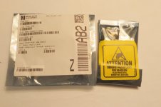
The pots that are installed on your circuit boards now are Bourns 3386P-1-501. This is a 300V, 1/2 watt, 320 degree turn pot, and is really tricky to adjust accurately. These pots were used for a couple of reasons, that start all the way back to the original design concept. The second generation Fortes were designed as an amp that produced beautiful music at an affordable price, and to do that Michael used a lot of very smart production shortcuts such as using one single circuit board in both the right and left side of three different amps (maybe even the model 7, but I don't know that amp). Ordering 8,000 of the same board is a lot cheaper than ordering 1,000 of this and 1,000 of that, and it fit the design goals.

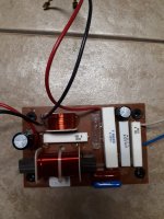
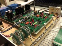
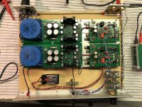
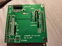
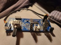
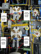
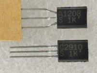
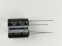
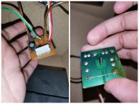
Anyway, because of this, and because the board has a staggered mount for the bias pots, when the board was flipped over to be used on the other channel, a vertical adjust pot would be facing downward on one side. Not helpful. Here's the pot that is in your circuit board now:

20220219_141525.jpg


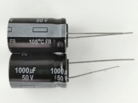
The outward facing adjustment allowed it to be mounted in any direction and still have access to the adjustment screw. Ideally, we would like to not only change these out because they get dead spots, but also make the adjusting process a lot easier. An ideal candidate for this is the Bourns 3299x-1-501, a 300V, 1/2 watt 25 turn, VERTICAL adjust trim pot that will fit right in.

20220219_141638.jpg


The Bourns 3296x-1-501 will work as well, and is just the military spec version; the 3299x-1-501LF is the same item but meets Rohs specs. These little guys are only 2-3 dollars each, so if you're good with a soldering iron, there's almost no reason not to change them on a 30 year old amplifier.

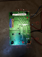
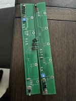
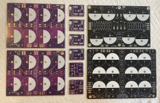
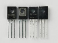
The 3299 works best because of the leg spacing:

20220219_141734.jpg


...which you can see is the same as the 3386. By getting a pot with a straight leg alignment, I can bend the center leg a little left or a little right to keep the screw UP on both sides of the amp.

20220219_145042.jpg


Okay, now that you have the parts, STOP. Before you turn on the soldering gun, GET A READING ACROSS THE LEGS OF THE EXISTING POT THAT'S ON THE CIRCUIT BOARD NOW. The last thing we want to do is install a pot with a lower resistance value than what was in there to start - the extra current flow can heat things up pretty quick. As a reference (only) my transistor bias was set at 175 ohms (the new pot went in around 250) and the output offset was 254 ohms (the new one went in at 330). If for some reason you forget to do this, install both pots at 500 ohms, and open them up during final adjustment.

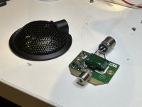
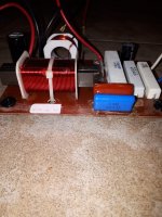
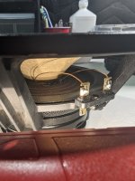
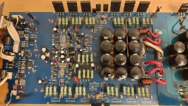
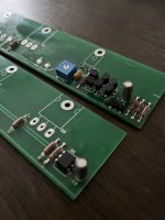
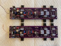
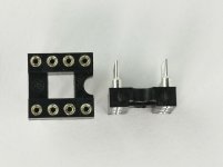
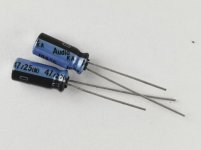
Your new board might look something like this:

20220219_142146_HDR.jpg


...with those nice brass screws easily accessible now.

20220219_143021_HDR.jpg


As you can see, the pot takes up about the same amount of space on the board, and being offset from the board, should dissipate heat a little better as well.

20220219_143042_HDR.jpg


Hope this helps out a few guys who are still holding on to their Fortes (like me!) as we go through some well deserved maintenance after 30 years of service.

Have you found a different way, or an improvement? Include it below!
  • Thank You
Reactions: PRR

Is there any such thing as "too much" inductance in a filter choke?

I've got another wacky question. Is there any such thing as "too much" inductance in a power supply choke? I ask because I have been winding my own power and output transformers for some time now with success, and just recently got around to trying an air-gapped choke. I made two revisions of it, one using a full-stack of iron from a microwave oven transformer. Original primary an two secondaries completely removed first. The second is slightly smaller. It uses a half-stack of iron out of an old APC UPS for enterprise/server use. Still pretty big though.

On the APC iron, I managed to wind 3294 turns of 28 awg. 115 ohms DC resistance. On the microwave iron, I managed 3030 turns of #28. DC resistance 147 ohms (its circumference is larger.)

My cheap LCR meter thinks they're both mosfets for whatever reason, even though it'll usually measure reasonable amounts of inductance. I tried measuring sine wave voltage drop across them, but there was no change in voltage at any frequency that I tried. So I tried injecting pulses into the circuit below and then measuring the frequency that the circuit oscillated at after the pulses. Then plug that frequency along with the known capacitance value into a LCF calculator. I don't know how accurate that was, but...

circuit a.jpg


The microwave iron version returned a reading of 39.518 H. The APC iron version returned a reading of 19.225 H. That was staggering. FAR more that I am used to seeing in a power supply choke. Only time I've seen anything close to this was in a very early Atwater Kent console radio. It used a large choke along with two smallish film caps for filtering. Likely because caps were still very primitive at the time. Aside from the risk of inductive kickback (and the physical size), is there any inherent disadvantage of using a choke of that size? A choke like this would be inherently expensive to produce, but I've got a stack of free iron and a virtually infinite supply of #28 magnet wire at my disposal.

In any event, I name all my projects for record keeping. This one is called "Legato."

Purifi PTT5.25X08-NFA-01 Woofer-Mid "Running Wild," Tweeter Level at +0dB/FLAT

I previously posted about my prototype with the Eton 5-312 running wild, no crossover on the woofer (there is a network on the tweeter, obviously):

Login to view embedded media
I was so tickled to learn that the Purifi PTT5.25X08-NFA-01 Woofer-Mid was a near-perfect "Drop-In Replacement" that I bought one!

First of all, that driver is heavy like a hand grenade. Lars Risbo was kind enough to fill me in that the 5.25 uses the same motor as the 6.5.

Yikes! So, the same motor, but the cone is circa 34% smaller in terms of pistonic area. I know that it is bordering on mental cruelty to post YouTubes of loudspeaker design progress... but, it's the best I can do.

As before, the demo track is Kate St. John's re-setting of the Tennyson poem "The Lotos-Eaters," which is based on a story from The Odyssey, and which also was set by Elgar.

I am hugely impressed.

Login to view embedded media
My next move will be to put a woofer roll-off from 3kHz up back in, and try that out.

Thanks to all who have given advice and encouragement. Oh, the other speakers are the assembled Sasandu Txes.

john

Occasional Big noise 100 Hz

Hello my friends, I have a Ming tube amplifier with 300B and 845.
Sometimes a loud noise appears on the speakers at 100 Hz as if someone flipped a switch. You hear the noise... as it appears in the same mode it disappears...
With the amp open during the problem with a plastic screwdriver, I touched all the parts without anything happening. Likewise when the audio is cleaned by touching the internal wiring, nothing happens. I attach the video below where the noise suddenly appears which in this case lasts 30 seconds and then disappears on its own.
Generally the noise at 100 Hz is corrected by adjusting the HUM balance, the trimmer connected between the 47 ohm resistors on the cathode of the 300B. In fact, by adjusting the trimmer when you don't hear any background noise you can flatten the output. Here too, however, a strange thing happens: to keep the two channels silent, I detect anomalous values. In the picture attacted the value.. with the measurements at the top without valves, at the bottom with the valves mounted, doesn't it look strange??

Login to view embedded media


Thanks in advance for your precious help

Giveaway / Raffle - Classic Aleph 30 amp boards + more (2023 Edition)

Once again I'm offering up a pair of fully populated Aleph 30 boards. Last time I raffled off a pair that I used when developing the Classic Aleph boards for UMS chassis. Those went to the UK. This time I'm raffling off the "first gen" group buy boards (PCB Rev V1.0d).

These boards just got taken out of my monoblocks tonight after ~1.5 years of faithful service. They use very tightly matched Harris/Fairchild SFP9610's on the front end, and very tightly matched Vishay IRFP240's for the power MOSFETs. I ran these as monoblocks using 20V donuts.

Why am I doing this? I'm finally putting my "new" (~1.5 year old?) boards into my monoblocks, and I'll be experimenting with sockets for the Q1&Q2 spots to do some "MOSFET Rolling". They will also use some 90's vintage Harris IRFP240 just for fun.

Added bonus - I'll include your choice of power supply board(s) - these will not be populated.
For a single donut stereo build: 1x "New original" F5 dual rail decoupled power supply board and 2 rectifier / snubber boards
For monoblocks: 2x V8 CRCRC power supply boards, 2x CL-60/AC Cap boards, and 4 rectifier / snubber boards
For 2 donut dual-mono build: 1x W12 CRCRC power supply boards, 2x CL-60/AC Cap boards, and 4 rectifier / snubber boards

All you could want to know about these boards is in the Classic Aleph Builder's thread Post #1

If you have a chassis with +/-24v power supply you’re almost there. Drop these in and enjoy!

Rules
  • If you'll install and use them within 2 months, you're eligible. I don't want these sitting in a drawer, I want someone to enjoy the Classic Aleph sound.
  • I’ll cover shipping within the USA. Outside USA I'll cover shipping up to $10 USD. I'll ask you to cover any additional cost.
  • These parts are used, but work just fine. If for some reason they get lost in the mail or arrive damaged in transit, that’s too bad.
  • I’ll keep entry open until 12 noon Eastern time on Monday 12 June 2023. From there, I’ll take the last post that contains all entrant names, randomize with random.org, and the person at the top spot will be the winner. I’ll post the screenshot - it’ll be the winner's responsibility to pm me with their shipping info.

Attachments

  • IMG_8861.jpeg
    IMG_8861.jpeg
    809.7 KB · Views: 312
  • IMG_8863.jpeg
    IMG_8863.jpeg
    620 KB · Views: 298

I built a Germanium RIAA preamp

I was in the mood to build something different and stumbled across a design for an RIAA preamp based on Germanium transistors. The schematic calls for P28 and MP38A transistors but I used MP13B and MP10B instead. MP13B is supposed to be low noise. The only change was an electrolytic coupling cap on the output because one was already used for the input. For a regulator I picked the NCV47551 because it was cheap and had very good noise and PSRR numbers. Power is supplied with a 12v linear wall wart so under load it's supplying 14v which is enough overhead for 12 volts out. One bodge was required on the regulator, the current limit pin should be grounded. The trim pot is to adjust the voltage.

Initially it sounded harsh and I decided to see what the distortion analyzer had to say. Input was 10mv at 1khz and output was reading 1.1v so gain of just over 40db. VCC was set to 9 volts and that was giving 0.9% THD. Increased VCC to 12 and distortion dropped down to 0.4%. I have some P27 transistors still in transit so I may build another board to compare against.

Attachments

  • w4noTDdh.jpg
    w4noTDdh.jpg
    55.1 KB · Views: 400
  • IMG_3520.jpg
    IMG_3520.jpg
    483.7 KB · Views: 365

Active Ribbon Design Considerations

I'm thinking about investing in a pair of RAAL 140-15Ds. They seem like very cool speakers, especially because of how far down they respond to. That brings me to one of my questions, so I'll get right to it:
1) For this specific tweeter, I read on audioexcite (http://www.audioexcite.com/?page_id=2523) that, even though it can crossover at lower, the recommended is about 3khz. Is it possible somehow to cross over lower (the spec sheet states 1600hz) even down to near it's minimum freq response (500hz) and still maintain good noise figures? DSP assisted?
2) From what I've read, ribbon tweeters usually need a transformer in order to match the impedance to whatever circuit they are a part of. Is there anything else to take into account? Ex. Usually for something like a zobel network you would usually use the DC resistance of the speaker in the calculation, but the 140-15D has a DC Re of .13 ohms.
3) Is there any kind of specific fail-safe circuit that should be ran specifically with a ribbon tweeter?
4) Anything else I should know?

For Sale Celestion SL600 Loudspeakers

We are selling this pair of Celestial SL600 loudspeakers on behalf of a customer.

They are in only fairly good condition with scuffs and marks on the suede 'Nextel' painted Aerolam cabinets - they were notoriously difficult to keep clean!

A legendary loudspeaker in many respects and we have tested them to be in good working order and sounding remarkably good for their age. Please note that upgrades were done to the crossovers and they now only accept bi-wire or bi-amp inputs as there are no removable external crossover links.

They come with their original user guide and frequency response plots for both speakers - they are consecutive serial numbers - 261565/6 - so are a matched pair. Documentation supports the upgrade work carried out in late 1985. There is also a reprint of a 1983 review from Hi-Fi for Pleasure.

PRICE:399$
shipping 30$

Attachments

  • s-l1600 - 2022-12-22T023704.743.jpg
    s-l1600 - 2022-12-22T023704.743.jpg
    321.6 KB · Views: 209
  • s-l1600 - 2022-12-22T023658.133.jpg
    s-l1600 - 2022-12-22T023658.133.jpg
    318.9 KB · Views: 214
  • s-l1600 - 2022-12-22T023652.790.jpg
    s-l1600 - 2022-12-22T023652.790.jpg
    248.1 KB · Views: 199
  • s-l1600 - 2022-12-22T023647.186.jpg
    s-l1600 - 2022-12-22T023647.186.jpg
    263.1 KB · Views: 227
  • s-l1600 - 2022-12-22T023641.947.jpg
    s-l1600 - 2022-12-22T023641.947.jpg
    275.1 KB · Views: 258
  • s-l1600 - 2022-12-22T023635.952.jpg
    s-l1600 - 2022-12-22T023635.952.jpg
    288.4 KB · Views: 207
  • s-l1600 - 2022-12-22T023630.544.jpg
    s-l1600 - 2022-12-22T023630.544.jpg
    298.8 KB · Views: 239
  • s-l1600 - 2022-12-22T023625.324.jpg
    s-l1600 - 2022-12-22T023625.324.jpg
    353 KB · Views: 208
  • s-l1600 - 2022-12-22T023619.868.jpg
    s-l1600 - 2022-12-22T023619.868.jpg
    393.6 KB · Views: 203
  • s-l1600 - 2022-12-22T023608.350.jpg
    s-l1600 - 2022-12-22T023608.350.jpg
    320 KB · Views: 455
  • s-l1600 - 2022-12-22T023613.738.jpg
    s-l1600 - 2022-12-22T023613.738.jpg
    320.6 KB · Views: 316
  • s-l1600 - 2022-12-22T023600.824.jpg
    s-l1600 - 2022-12-22T023600.824.jpg
    294.8 KB · Views: 211

Help? Bogen CHA70a amplifier schematic???

I have purchased an operational Bogen CHA70a amplifier and may have bittten off more than I should have. Although I can muddle through without a schematic, I prefer to use one on anything I haven't tangled with before. Not only have I not tangled with this model, I haven't worked on any Bogen amps before, so any help that someone could offer would be greatly appreciated. I am a newbie to ANY forums here and did not really join up to start asking favors. I am worried about this one because the usual sources have failed me. i have tried Antique Radio Supply, el34world.com, Schematics Unlimited, Electrotanya, and several places I cant remember as well. I checked with Sam's Photo Fact and even they did not offer anything for sale. This must be Bogen's Edsel ! Anyway, If anybody knows where i couod get one, i would be willing to pay for it as long as it isn't too high priced. Thanks......dimwatt.

Inherited DIY Tube PreAmplifier

Hey all,

I recently got the chance to acquire a DIY Tube PreAmp for 300€, it was inherited to the person so they couldn’t tell me that much. I have also no clue when it comes to Tube Amplifier since this is my first one, so I’m curious if you guys can tell me some more about it, was it the money worth? what exactly is it, a rebuild? I know that it has 4 Line.Inputs + 1 Tape and a Phono (MM) Input.

Thank you in advance

8F723124-5F39-4F3B-B63E-D535F24AFDF6.jpeg
EB6655FE-366D-40DE-9520-D3B6C49EC450.png
37D767EE-7612-4DA6-BE0F-82515270B9CA.jpeg
56DAB641-C224-4518-BBA5-E45163A224D2.jpeg
88D424C7-3103-443D-BD2F-6B248BF7D41C.jpeg

For sale 2SC2910 /2SA1208 ; 2SC3503 / KSA1381 ; 2SK772 + PANASONIC , NICHICON , DIODES & IC SOCKET

PAYMENT PAYPAL
Shipping ( registered priority )
EUROPE = 6,50 euro ( box + antistatic bags )
Rest of the world = 7,50 euro
Below original photos
If you buy for 70 euro or more shipping is free.

Minimal order quantity = 1 set
10 sets 2SC2910-S / 2SA1208-S ( S-Grade 140 - 280 )

SANYO NPN / PNP 160V 70mA package: TO92MOD
1 set = 25 pcs. 2SC2910S + 25 pcs. 2SA1208S ..= 14,95 euro
-------------------------------------------------------------------------------------
8 sets 2SK772-E
SANYO N-FET 10mA ; idss 2.5 - 6.0 ; package: SPA
1 set = 25 pcs. 2SK772-E = 10,35 euro
------------------------------------------------------------------------------------
4 sets 2SC3503-E / KSA1381-E ( E - Grade 100 - 200 )
KSC3503 - E ( obsolete part )
SANYO / ON SEMI 300V ; 100mA ;
2SC3503E ( TO126 ) / KSA1381E ( TO126 isolated )
1set =25 pcs. 2SC3503E + 25 pcs. KSA1381E = 22,54 euro
--------------------------------------------------------------------------------------
10 sets Nichicon KA SERIES 105C
47uF/ 25V ( 5 x 11mm ) ; -40...+105C
1 set = 25 pcs. = 4,60 euro
----------------------------------------------------------------------------------------
10 sets PANASONIC FR capacitors 470uF / 63V
1 set
= 10pcs. = 6,66euro
470uF / 63V 12.5 x 25mm , p=5mm
-----------------------------------------------------------------------------------------
5 sets PANASONIC FR 1000uF/25V
10 x 20mm , p=5mm
1 set = 10pcs. = 3,45 euro
---------------------------------------------------------------------------------------------
1 sets PANASONIC FR 1000uF/50V
SOLD

---------------------------------------------------------------------------------------------
2 sets STPS20120D single schottky diode , Mfg. ST
SOLD

--------------------------------------------------------------------------------------------
2 sets LF33ABV Stab. LDO , Mfg: ST
SOLD

---------------------------------------------------------------------------------------------
2 sets Precision socket 8 PIN
SOLD
----------------------------------------------------------------------

Attachments

  • 2SC2910 2SA1208  DD.jpg
    2SC2910 2SA1208 DD.jpg
    81.1 KB · Views: 94
  • 2SC3503 KSA1381 DD sm.jpg
    2SC3503 KSA1381 DD sm.jpg
    76.7 KB · Views: 111
  • 2SK772E DD  sm.jpg
    2SK772E DD sm.jpg
    52.2 KB · Views: 97
  • STPS20120D DD sm.jpg
    STPS20120D DD sm.jpg
    67.4 KB · Views: 78
  • PIN8 PZ DD sm.jpg
    PIN8 PZ DD sm.jpg
    47.7 KB · Views: 86
  • FR 470 63V DD SM.jpg
    FR 470 63V DD SM.jpg
    50.4 KB · Views: 79
  • FR 1000 25 DD.jpg
    FR 1000 25 DD.jpg
    173.7 KB · Views: 80
  • FR 1000 50V DD.jpg
    FR 1000 50V DD.jpg
    200.9 KB · Views: 86
  • KA 47 25v DD SM.jpg
    KA 47 25v DD SM.jpg
    51.2 KB · Views: 84
  • 2SC2910.pdf
    2SC2910.pdf
    44.3 KB · Views: 79
  • 2SK772_Sanyo_.pdf
    2SK772_Sanyo_.pdf
    77.7 KB · Views: 71

bootstrapped opamp to linearize an output stage

I had a wonder about bootstrapping the supplies for an opamp in an output stage to linearize it. Then I spent way too long in LTSpice...

bootstrapped_OS_bipolar_schematic.png

There's a lot going on here - the input stage and VAS are pretty standard, except perhaps that the VAS is very lightly loaded at 1mA standing current and only driving an opamp input.

There is capacitive bootstrapping to provide opamp rails that track the output voltage (no attempt at considering protection circuitry yet), and this is used in a non-inverting configuration with about 1.1 gain factor. The compensation for this was mainly trial and error and I don't claim it any good other than to allow the simulation to run(!)

The opamp rails are limited to 30V by a zener and decoupled with 100nF. Since they swing with the output there is plenty of headroom for driving the drivers/output transistors right to the rails, and the 1.1 gain factor means the VAS doesn't have to get particularly close to the rails, relaxing its requirements.

I have simulated with some ripple on the +/-45V main rails (at different frequencies to allow their effects to be identified in an FFT plot). I've also simulated reactive loading by driving the opposite end of the 8 ohm load with 10V at yet another frequency.

It turns out the OS with opamp is pretty linear (IIRC about -100dB distortion) - its able to reject the simulated reactive load by 90dB or so by itself, but the overall negative feedback loop easily knocks that down out of sight:

bootstrapped_OS_bipolar_spectrum.png


The fourier analysis claims 0.001495% at 1kHz (40V peak) altogether upto the 80th harmonic. You can just see the 200Hz and 500Hz breakthrough from the rails in this plot, attenuated from 1V on the rails to about 30uV at the output.

The overall gain is x 20 (26dB), and from 45V rails with 1V ripple (ie dipping to 44V) it clips at around 42V peak.


The elephant in the room is how robust can such a scheme be made, given any fault on the output risk putting 45V or more onto the opamp in various ways.

Anyone running Raspberry Pi/MoOde with Douk Audio U2 Pro?

I recently got a Pi 4B up and running to be a flac player, using the 8.3.7 MoOde, USB drive and USB DDC. The software found the correct driver for my older DDC, a Peachtree X1. When I switched to the Douk U2 Pro, it gets configured as HIFI DSD, and the DSD light comes on. While it supports DSD, I need PCM. It worked fine on W10. MoOde S/W apparently uses the Linux kernel 6.1.21 as shipped with Raspberry Pi OS Bulleseye.

At the suggestion of Tim, I sent some questions to Douk. The add for the device claims:
  • Native ac OS 10.6 and above, can use the system's own driver. And Native Linux with UAC2 compliant kernel also can use the system's own driver.(Has tested on Ubuntu and Daphile systems, based on INTEL X86)
Has anyone successfully configuered the Douk U2 Pro with MoOde? If so, please help this Linux illeterate. TIA.

Rohde & Schwarz UPV / UPP Audio Analyzer Thread

Probably not many UPVs owned privately, however future will tell.

As with the rest of the Audio Analyzers from R&S, the UPV is discontinued as the AKM ADC is no longer available.

There are a few variations as already known from previous UPL/UPD units.

<February 2007 with FMR6 RS232, LPT and VGA output
March 2007 with FMR7 NO RS232, LPT and VGA output
March 2012 with FMR9 and different digital board (NO RS232, LPT and VGA output)
February 2015 with FMR11 and different digital board (NO RS232, LPT and VGA output)

Not sure at the moment if by using a FMR9 with a pre 2012 Digital Board will let you run the RS232 ports for example.

Versions after 2015 can be equipped with and SSD as the main drive, whereas the olders ones use a Fujitsu 5400rpm 40GB.

Pictured, FMR6 1.5GHz Celeron unit with 512MB of RAM DDR2.

Attachments

  • IMG_1555.jpg
    IMG_1555.jpg
    814.1 KB · Views: 237

  • Locked
Change in ohms of bookshelf speakers

I have pair of bookshelf speakers 6ohms 3 way

Both when measured shows 6ohms

But one of the speakers suddenly shoes 20-40 ohms

Is it a problem of concern?


After few days it automatically goes to 6ohms but again changes in few days.


So I decided to look into it if it had some crossover issue but found nothing.


Attaching pic of crossover

Attachments

  • Collage_20240106_221132.jpg
    Collage_20240106_221132.jpg
    285 KB · Views: 121

Help with Sony TA4650 VFET amp high power supply voltage

Hi Sony VFET amp experts, I am rebuilding my Sony ta 4650 VFET amp. After replacing the old capacitors , zener diode 1T43M with with a 7.5v zener diode , replacing all other diodes I am getting +-53vdc on the 2 large 47,000uf/50v caps instead of -+45vdc what might be the cause of this high voltage , your kind help is greatly appreciated . Thanks
Projects by fanatics, for fanatics
Get answers and advice for everyone wanting to learn the art of audio.
Join the Community
507,666
Members
7,883,339
Messages

Filter

Forum Statistics

Threads
405,989
Messages
7,883,339
Members
507,666
Latest member
Fpa420