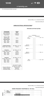
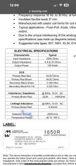
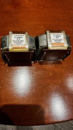
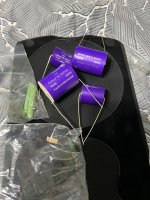
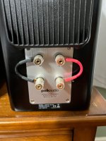
Hi all. I picked up some Hammond 1650r outputs, because I'm getting back into the hobby and wanted something cheaper to experiment with. 5k P-P, 318ma, 100w, dual secondaries. After I ordered I noticed the part number was "1650Ra". Basic specs were the same, size/weight/imoedance, so I figured it was just a part number change. According to Hammond, the only change was from dual secondaries (R), to a single (Ra) 0-4-8-16.
My question is, no matter how they're measuring, how is the stated primary inductance SO different? I've attached pics. Stated is that the entire primary of the Ra is only 14 Henries, but just one half of the R is 320 Henries? Are they measuring one at voltage and the other not, maybe? Measuring the Ra, P-P, I get the stated 14h.
Thanks so much for any info. Soon I'll start a thread for the build.
I just acquired an all original vintage Accuphase C-200 preamp. There are a number of film capacitors (1uf or 2.2uf) on the various audio boards, and I was hoping someone could advise on what type of materia these caps would be made from. The brand appears to be "NTK" but I didn't find anything online from that name. I've seen a couple examples of restorations where some of these caps were changed out for modern poly caps, but I thought I should learn more before replacing the originals as I'm sure they were premium parts back in the day.
Anyone here know if there's a setting for this? I poked around some but couldn't find any internal audio settings to even look at.
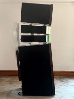
This is a simple setup just coming off of an LG widescreen, everything worked out of the box except for the audio.
Owners manual clearly states that the volume control is supposed to work.
I am very frustrated by the fact that so many post attachments are in .ASC files....these are unreadable on a Mac without installing
3rd party software. Surely .pdf format is preferable to what is a very old security orientated format?
After years of designing various types of line arrays at McIntosh, Snell and Bose, I thought I would start a conversation about what I've learned over the years, specifically in how simple modeling can lead to an understanding of line array phenomena.
While I am not a Matlab wiz I have found that Excel is good for modeling simple arrays and will give you a good understanding of what is going on. Through some simple models I intend to illustrate all of the line array phenomona and explain their root causes. Through an understanding of basic phenomona we can take steps to control polar patterns and achieve the performance that we might want.
This is not going to be a discussion about "if I put 10 Vifa units in a row, will that sound real good?". What this is is more about "what causes the lobing ('lobe-ing") and how do I control it?"or "What determines my vertical directivity?".
Hopefully some will find this interesting and those of you that are better at mathematical modeling than me may be inspired to work up some better array models than I have.
How do we calculate the performance of a line array. The basic array model
Lets say we have the simplest possible line array, 2 elements set some small distance apart. If we stack them in a vertical line and then go out from the elements and upwards so that we are 30 degrees above the elements, then how would we calculate the response of the pair of elements? Or if we want to know the polar response for some frequency, how would we calculate that?
The basic premise of array modeling is that the individual elements can be thought of as vectors that are added in space. They are assumed to be independent of each other (i.e. no mutual coupling or other interactions) but the phase of each element must be taken into account. If we take our geometry and calculate the distance difference as viewed from our 30 degree observation point, take that distance difference and convert it to a phase difference we can predict response. All we have to do is think of the 2 elements as 2 vectors with some relative phase shift between them that we (vectorially) add to get a combined array response.
If you don't remember how to add vectors it is quite simple. Start with a magnitude and phase for each element and then convert to rectangular format (using cosines and sines of the angle) and them add the "real" parts and the "imaginary" parts together. The Pythagorean Theorem will then let us convert that back to a magnitude. Once added we can convert the results to dB if desired. This is really all the spreadsheet does.
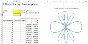
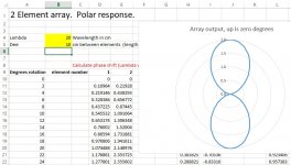
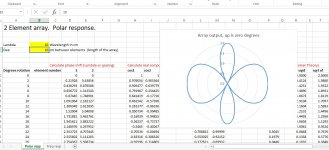
I'll confess that I am not Matlab proficient so I like to use excel to set up spreadsheets for any particular array. I've included a 2 element polar curve example. In this example column A gives the viewing angle that steps from 0 to 358 in 2 degree steps. Columns D and E define the actual geometry that defines the excess path length of each element (here only 2 elements). This is the calculation of phase difference between the 2 units. Columns H and J define real part of the radians of delay, L and M the imaginary, and P through T the magnitude of the pythagorean theorum sum. By breaking into real and imaginary parts we can sum any number of vectors as called for by the complexity of our array.
So the desired result is column T that is plotted as an Excel "radar" plot. This is an overhead view of the typical array. Up on the graph is 0 degrees and down is 180. In normal conditions the array directivity would have driver directivity added to it. In fact, if all elements aim in the same direction then total directivity is simply the sum of array related directivity plus driver directivity. So, typically, the front to back directivity is significant. Its never bothered me to see plots with no driver directivity, I just view that as the "second factor".
Note also that the polar plot is a cross sectional view of a solid of rotation. For one wavelength spacing as shown you would have a top like shape with a fat rim and narrower axle. (We can talk about why the rim is fatter later.)
The spreadsheet has 2 fields where you enter a number, one for Lambda (applied wavelength) and the second for "Dee" or distance between elements. Our first check of the array math working right is that when Lambda = Dee then our two units are one wavelength apart and see a full height peak at +-90 degrees. This would make sense in that rotating 2 elements to 90 degrees, with them one wavelength apart, should see them come back into phase. Something that should eventually make sense is that frequency doesn't really matter at all but the relationship between spacing and frequency is key. That is, the array definitions will always have a "Lambda/Dee" factor. Doubling Lambda and Dee at the same time will always return the same polar curve. This is just a way of saying that all arrays are scalable...
Also note that the height of the 4 peaks of our plot are all 2.00, this coming from the value of the in-phase sum of 2 unit vectors.
I've attached 4 sims with various ratios between wavelength and physical spacing.
This seems like enough to digest for our first look at array modeling so I'll let that soak in for a while and see if there are any questions or comments.
David Smith
Hi 🙂
I have been out of the speaker building game for quite a while and wanted to spice up the top section on my MT122 (speakerplans.com). I have already been running them with an added DE250 but want to split up the 12' section into separate cabs and make a MEH with 2x 4NDF34 and 1x DE250 to go on top.
Previous DIY for me has mainly been bass subs(bandpass horns / tapped horns) and some bass reflex tops.
This will be a completely open sourced project where I share everything via Github
Currently I am getting (re)familiar with modelling software (Akabak and hornresp) and trying to get a smoothish workflow for prototyping, happy for suggestions and links to add to my collection.
Hopefully have some plots of the horn and CD soon. 🙂
Lundahl LL1692A P-P Inter-stage Transformer / Line Output Transformer available for sale. Asking $150 USD (Pair) , will ship anywhere at buyer's expense.
A few years ago I built a stereo power amplifier with the LM3886 chip amp and have been using it daily with a single iPhone source as my primary sound system. It sounds great, it's a HiFi design with high end components, but it's also a bit too minimal, with only one stereo input and one stereo output. I am planning to build a HiFi preamplifier with an input select switch, volume, tone, and balance controls. My audio sources will be an iPhone, CD player, and TV. I read that these have a relatively high output voltage, so I decided on a moderate maximum gain of ~13 db, which is set by a Baxandall active volume control circuit.
It seems like the best performing audio op-amp that still comes in a DIP package is the LM4562, so that is what I plan on using for the op amps. The preamplifier uses a high pass and low pass filter at the input to set the bandwidth, then an input buffer stage with parallel LM4562 op-amps. The input impedance is set to 47.1K. The input buffer stage is followed by a Baxandall active volume control circuit. After the volume control circuit is another parallel op-amp buffer (not sure if this is necessary), then a Baxandall tone control, again followed by a parallel op-amp buffer. Then a balance control circuit, followed by an output buffer consisting of two op-amps in series.
I am trying to optimize this circuit for low noise, good bass response, and clear mids and highs. I have designed and built amplifiers with chip amps like the LM3886, LM386, TDA2050, and TDA2003 before. But I don't have a lot of experience with op-amp based amplifiers, so I was wondering if anyone could check out my circuit to make sure I'm not missing anything?
I understand the importance of having a high impedance at the preamplifier's input, but is it necessary to set the input impedance at each set of op-amp buffers? For example are the 47K input impedance setting resistors R5, R8, R17, and R21 necessary?
If they are, would it be better to set them to a lower resistance for less Johnson noise? The datasheet says that the LM4562 can drive 600R loads, so can I set the input impedance of all buffer stages after the input to 600R instead of 47K?
The input impedance of the preamplifier is 47.1K, should I balance the input bias currents of the op-amps (U1 and U2) by placing a 47.1K resistor in the feedback loop?
Can I balance the input bias currents of U4 (in the active volume control section) by placing a ~500R resistor from the positive input to ground?
The values of the 2 uF DC blocking caps around the volume, tone, and balance pots were chosen arbitrarily based on the value of C1. Is there a better value for those?
One pair of very nice Electra-Print ST3KB output transformers. Perfect for a 300B amplifier. I bought the output transformers from Electra-Print / Jack Elliano in 2006. The transformers have been in storage for 15 years. They are in very fine condition.
Specs:
Primary Impedance - 3.3 Kohms
Max Current - 125 mA
Max power out - 20 Watts
Multi-secondaries - 4,8,16 Ohms
Price: 250 Euro + shipping. The transformers are located in the EU.SOLD
One pair of Electra-Print SE Interstage transformers 5K/5K, 35 mA. I bought these interstage transformers from ElectraPrint / Jack Elliano in 2020. I have only used them for a very short period of time. They are in like new condition.
Price 130 Euro + shipping. The interstage transformers are located in the EU.SOLD
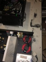
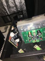
There are several teardown videos of the LRS series on youtube, so I have not bothered to document the primary side. There is a flyback converter and a fully isolated transformer. Feedback is done via two optocouplers. One seems to be for regulating the output voltage, the other one is labelled O.V.P. (overvoltage protection?) in the block diagram of the data sheet: https://www.meanwell.com/Upload/PDF/LRS-150/LRS-150-SPEC.PDF
Anyway, the secondary side of the PCB seems to be designed for several versions, some of which seem to use active rectification. All those positions are unpopulated, so the secondary side, ingnoring the regulation and protectio part, consists of:
two secondaries made of multi-strand HF litz wire which are already paralled on the transformer's solder pins
another single wire secondary that is connected to the higher power secondaries on one side and simply left open on the other side
a Schottky diode in TO-220 casing with the two diodes paralled with a wire bridge
one snubber consisting of a 35 R resistor and an unknown capacitor parallel to each diode (strangely, one is very close and the other one has a long pcb trace --> why didn't they simply use one snubber?)
a CLC filter consisting of 4x 470 µF in parallel, an inductor and another 470 µF
So what strikes me: why did they employ half wave rectification when then could have connected those two secondaries in series, creating a center tapped secondary? Then they could have used one of the diodes in the package on each side of the secondary, resulting in full wave rectification and hence much smaller ripple with exactly the same component count? They could even have economized some of those electrolytics!
The other thing that is not pretty: There is an isolating sheet made of FR4 of roughly 0.2 mm thickness between the pcb and the aluminum back side. Some of the wires of the through hole components press directly onto this isolation sheet, e.g. the blue input cap (or is it a surge protector?) right on the mains input. G-shocks and vibration could cause its quite sturdy wires to grind through the insulating sheet, or the solder joints could break over time. Yes, its a class I device, but simply clipping the leads would have eliminated this failure mode.Other than that, I am happy. No load power draw is about 0.3 W. Connecting a 24 V fan that draws about 0.8 W gives me an incrase to about 1.3 W, so excellent low power efficiency. I have not yet measured ripple.
How about stacking two of these to obtain +/- 24 V? There is a video on youtube where someone stacks three LRS 150 - 48 to obtain 144 V. The data sheet says nothing about not connecting the secondary sides. The only thing that has me uncomfortable is that the secondary side has three EMI caps to earth (you can see them better in the teardown videos).
After having udge problems to find the transistors VP0120N5,
I finally bought the last stock of parts VP0120N5 manufactured by Supertex (same as VP0116N5,VP0216N5, VP0220N5) available on the whole WEB....
I you have an old hifi amplifier such as Krell KSA100, or Spectral DMA200 (as I have), I can bring you a few pieces as a life insurance...
If you are interested just mp me....
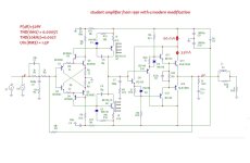
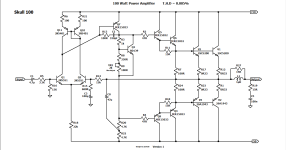
Attached is my 1991 student amplifier with a modern modification.
modifications:
*element base
*progressive correction
*optimization of modes
This is how the amplifier was assembled in 1991. Initially it was assembled by hanging installation, the initial current of the output stage was very small (10mA - Class B), now I have increased it a little.
power supply without a middle point, because The topology of the circuit is symmetrical with respect to the power supply and there is no need to base the elements on the power ground, so a virtual ground is formed.
For Q7 KQ8 small radiators are required, because It is necessary to dissipate 200 mW of heat on each transistor.
The thermal stability of the output stage is ensured by the arrangement of all Q9Q10Q11Q12Q13Q14 transistors on one radiator.
You can regulate the initial current by pairwise selection of resistors R19R21.
Maybe this scheme will be interesting for someone to repeat - it worked for me for about 10 years.
I've asked about modeling software before, but I wanted to ask about Mac specifically. I do have access to a new Windows laptop, but at work, and really don't want to bring that back and forth. Hence the interest in a Mac package.
For simulating sealed box woofer designs, maybe ported later on.
Sophisticated analysis of like port tube resonances and power rolloff at higher frequencies not necessary for now.
BUT output in actual SPL is a must (i.e. the high frequency response can't just go to "zero" it has to be actual dB)
MUST correctly calculate multiple drivers in one enclosure to actual SPL...since the main point at this time is to compare single versus double versus triple etc drivers all in the same air volume. And also to screw around looking at the true efficiency at the lowest frequencies and what affects that.
I want a Subwoofer thats small footprint but still creates decent pressure in a medium size room. Say if I use SB Audience Open BAffel Woofers 12-15" and the back part of the box make a full sponge based back like Aperiodic vent. I dont want to have a 70 litre sealed box so was thinkig if Aperioid can give me bass. I am happy even if it covers 50Hz well. Searched a lot but no where I could find a aperiodic small box subsolution.
I have a pair of decent loudspeakers—Braun LS200. I discovered these speakers have Qtc of 0.5 on their closed boxes bass system. I’ve read that the low Qtc suits to classical music or any kinds of music that require bass’s precision and accuracy. Regrettably, I rarely listen to classical or jazz; but pop, soft rock, and sometimes disco. The LS200 performs well, however, I felt I wasn’t totally satisfied with their bass response. I think it’s too TIGHT and a bit too LOW efficiency. As a result, it led me to add an active equalizer to the system at present. To date, I no longer want to use the EQ. So I’d like fix the problem at its cause, that is the speakers. As mentioned earlier, the bass system has Qtc of 0.5 which should be the root cause. I know one method to increase the Qtc is to decrease the cabinet volume. But, I’m just curious is there any method to create a variable Qtc? So I could return to the factory design whenever I want.
In my small living room where my front mains have to live in the corners, I’ve been thinking about employing horns or a ~5”~6” coaxial as horns seem to require a seasoned designer. I believe (not sure) I want to tighten up the dispersion as low as possible from a maximum 7” diameter.
Being so close to the walls and right by the loveseat makes me think I want to attenuate as much off axis response as I can from mentioned size. Diffusers and absorption are not an option considering the size needed to perform a wideband treatment of the first reflections. If a wideband treatment isn’t employed then the image suffers in a different way, again, I believe.
I’ve looked at many coaxial drivers thinking that the tweeter would be horn loaded by the cone but just about every response graph looks super ragged compared to the separate component drivers I usually would consider. I must be missing something here. For instance, I see tweeters having a recommended high pass of like 3.5khz in the middle of a 6” or 7” woofer. So the woofer looks to be breaking up in or around the filter as well as beaming. Some high end coaxials seem to be designed in this way, does it all come together in a well behaved power response that the raw graphs don’t demonstrate?
The listening space I’m trying to make the most out of. There’s a few inches of wiggle room with the lamp/shelves but not a whole lot. I’m already planning on building short stands to raise the bookshelve speakers to where the woofer and especially the higher frequencies are as minimally obstructed as possible by the loveseat. I wouldn’t mind a nice coaxial mounted high enough to completely clear the armrest.
Am I thinking along the right path about horns or coaxials to control directivity? Here’s examples of what confuses me.
I’m not shopping in this range but it’s a good example that what I think I’m seeing is across the board in price with coincident style drivers.
I have build Elektor mini crescendo bach in the 90's. last year i re-caped it and re-wired it.I also use a separate and stabilized power suplly for the first stages. The amp is very qiuiet and sounds great. Two months ago left channel started to sound very low. I had to turn on and off a few times in order to recover. Some days ago this trick did'nt work. Left Channel continues to sound low. Any ideas?
Please see section 4.2.3 (page 22) in application note https://www.ti.com/lit/pdf/tidu035, there is a 3rd order all-pass filter producing a fixed delay of 155.28uS from 20Hz to 3.814Khz. The time delay of filter is shown Figure 31.
How do I modify this filter to produce a delay of 72.5uS till 6900Hz?
My Onkyo P304 treble potentiometer is becoming unresponsive and I am considering my options.
Undertake a diy replacement, (if a suitable alternative component is available)
Remove, strip and attempt a diy repair of the potentiometer if at all possible.
source an original -which could take forever … and a day, and is my least preferred path.
Replace the P304 preamplifier.
I am not seeking a debate on which is a better pre-amp, or the availability of modern, better, etc.
My system consists of an Onkyo P304 pre-amp and Onkyo M-504 power amp. Denon POA-2800, Luxman PD284, Linn LP12, Revox A77, SSll valve preamp with a pair of ACA Monoblock amps through Energy Veritas 2.1 bookshelf speakers.
Needless to say, I am very happy and comfortable with what I have, and would prefer to retain what I have, rather than go down the rabbit hole for bigger and better.
Having said that, is there anyone who has had similar issues and managed to repair, or replace using a suitable alternative?
Last summer I built a TSE-ii with 300b tubes -- it took a little while to get everything sorted (entirely due to my shoddy craftsmanship), but now that it's all together it sounds awesome. Thank you, George!
I have Shuguang 300b-z black treasure tubes in it currently. The switch from the basic Electro Harmonix 300b's to the 300b-z Black Treasures made a big improvement! I remember reading on the Tubelab site that the output transformer has even more impact on the sound of this amp, which has piqued my interest.
I currently have the big Edcor transformers on it (CSXE-25-5k), but I'd like to try something different. I was hoping to get some Lundahl transformers, but they have so many options and I'm not sure which would be best for the TSE-ii. I would appreciate anyone's help selecting. The list of Lundahl transformers is at: https://www.lundahltransformers.com/tube-output/
I currently have the 300b's biased at 62mA and B+ voltage is 342 v. I'm using Tekton Lore speakers, which are efficient enough, and I use the 8 ohm tap on the Edcors with no problems.
I was hoping to use a OPT with a 5k ohm primary impedance. Lundahl has a few options there. Their US rep recommended the LL1663 or the LL1623. I'm told though, that the maximum primary voltages for these transformers are 200V for the LL1663 and 270V for the LL1623. Is that a problem with my B+ of 342V? The "max power capability at 30hz, single ended" is 8W for the 1663 - might that be a bit too low for the TSE-ii running 300b's? Also, I'm not sure what the "Configuration" column refers to, and which would be better as a configuration "B", "C", or "-" (really not sure what that last one means...)?
But I also see on that list that there's also the LL2769, with a 4.7k Ohm primary. Maybe this would be a good option? Are there any others that would fit the TSE-ii well?
Again, I'd be grateful for any guidance and to hear your thoughts. What specifications would I need to give Lundahl? Since these OPTs are for a single ended amp, I understand they need an air gap. How large? Does that relate to the bias current through the tubes of 62mA? Lastly, do I need to make any decisions regarding the type of core of the transformer and/or the material used (amorphous, etc.?).
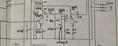
I had an early 90’s era Cary Audio SLP-70 preamp recently fully refurbed.. It is the Line version only without the Phono section on the PCB.. So I found the Phono schematic for it and had the board populated by a tech.. What do you guys think of the RIAA EQ Filter circuit of the All 12AX7 Phono section? Are those 1N4148 signal diodes on the cathodes of the 12AX7’s?
I attached a schema of the Phono stage section.. I have also seen on the net recent photos of latest revision of the said preamp, and the “C9” cap filter part of the RIAA EQ has been omitited and jumper wires were put in its place (check attached photo I found on the net with the Jumper Wire encircled in Red ..) I’m not sure if I have to omit C9 too, or just follow the schematic shown here.. So far to my ears, without the C9 (0.1uF), there is a lack of bass response.. I haven’t tried it yet with the C9 in place.
Any info you guys may share would be greatly appreciated..
I've wanted to make a decent bluetooth speaker for a while now, and have been slowly collecting the parts to do so.
The goals here are pretty standard:
Usefully loud
Decent LF output
Wide dispersion
Long battery life, and easily-changed batteries
Sound good
Easily carried across a field
There are some other features that I'm planning on building in, which make this more geared towards the sort of work I do.
My "reference" for this build is a Bose Soundlink Colour, in red. It's super-compact (as thick as a decent book, and a similar-size front to a CD case) and sounds reasonable at low/mid volumes. Turned up, some LF compression kicks in to rescue the tiny drivers. It hits 87dBC at 1m when playing pink noise. NB - the LF output has disappeared entirely by that point, and it only got to 90Hz to start with.
I looked around online for bluetooth speakers to see if there were any that were worth just buying outright, and saving myself a lot of time/effort. The UE Hyperboom looks pretty good, and the JBL Xtreme looks okay, too. However, I'm pretty sure I can do better.
Here's the prototype far: Login to view embedded mediaLogin to view embedded media
In total, there are:
4x Kartesian Sub120_vHP (the ferrite 4" mini-subwoofer)
2x Lavoce TW131.00
2x SB Acoustics 8x5" passive radiators
1x Zoudio AIO438 amplifier
The cabinets are re-used from another project, but they're doing the job for now. The planned cabinet will be around 20cm square at the top, and 35cm tall. The 4x Sub120 drivers will be in pairs on L/R sides, and PRs will be front/back. That way, I've got complete force cancellation and the speaker shouldn't walk around much.
HR sim for 2.83v into each driver: Login to view embedded media
Which is very good for a 11L (net) cabinet. I did try simulating with other drivers, ranging from Fostex 6" full-range units to 10" PA drivers, to see if anything else would get close. They often managed more efficiency above 120Hz, but I didn't find anything else that would keep up below 100Hz. Since there's a limited amount of voltage swing available, I didn't want to apply lots of LF EQ and run into clipping.
The Zoudio amp allows a useful amount of DSP functionality, so I've been playing with the crossover to make sure the tweeters cover more of the midrange (to ensure wider dispersion) but don't run into trouble from doing so. These Lavoce tweeters have held up well so far, but obviously the centre-to-centre distances are large at the moment, and the vertical off-axis response is weird at best. Final tuning will have to wait until the final cabinet is built.
For now, though, the prototype hits 103dBC@1m playing pink noise, beating the Bose speaker by 16dB. More, if you count the LF where the Bose was ~10dB into limiting. The extra octave of LF extension is nice to have, too.
For batteries, I'm planning on using some 18v-rated (they're more likely to be 20V once fully charged) power tool batteries. The advantages include:
Easy to swap out
Easy to charge
Warranty
Can use them for power tools
The disadvantage being they're expensive. That's okay, though. I want this project to do well, and sometimes that means throwing some cash at it. I decided against DIYing the batteries after realising that making them easy to swap out would get quite tricky. With the power tool batteries, you can find battery holders/adapters so the battery will slot in as if it's being installed in a tool.
Finally, I'd like to (briefly) discuss one of the not-so-standard features I'll be including:
- The Zoudio amp can be programmed and reprogrammed quite easily, and I'm under no illusion about the efficiency of the Kartesian mini-subs. In order to multiply the usefulness of this speaker, then, I'll include a couple of NL4 SpeakOn sockets and some switches. The idea is that I can disconnect the internal speakers, and power some larger, more efficient speakers. I have plenty of PA speakers around, some of which are very efficient indeed. For the times when I need more coverage/SPL and still need to run on batteries, this little speaker will be rather useful.
I think that's everything for now. The next steps will be to buy up some batteries, and build a better cabinet.
I had not planed on "showing" this new version of the NaO Note just yet, but with the up coming release of the Linkwitz LX521 I thought I should get it out there. It still has to be finalized, which will come some time this winter. There is just more to do in the spring, summer and fall other than to work on speakers. 🙂
Please see my NEWS web page or a brief look at some details about the speaker.
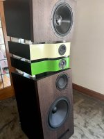
A couple of years since my last post due to real life (tm) not leaving any time for speakers but I had to post about my very positive experience with the Tangband W8-1772... 👍
For several years my daily drivers have been a "never quite finished" 2 way system with my old now somewhat battered Coral Flat 8 Mk II and an Aurum Cantus G2 ribbon tweeter:
Yes, the crossover is still sitting on the top of the cabinet (much to the chagrin of my other half) and you can probably notice the aluminium dust cap has been pushed in and buckled as well a few years ago thanks to my at the time 2 year old son... The dust cap damage pretty much ruined the treble response as a full range driver but didn't have much effect with the ribbon tweeter already in place as a 2 way design. They have been in use like this for at least 5 years and sounded pretty good.
Then a month ago there was an accident that involved the speakers getting blasted at full volume on a 50 watt amplifier for over 15 seconds before it was shut down. Wasn't me, I wasn't there at the time but I did hear it happen in real time over the phone which was quite distressing. Needless to say damage was done. 😢 Both ribbon tweeters suffered minor damage - the ribbon foils were overheated and have stretched slightly so they're no longer under proper tension - the foils lean back slightly in the gap and they don't sound quite right (mainly a loss of sensitivity) however a new set of foils will restore them to full health again.
However one of the Coral drivers was irreparably damaged. I didn't realise it before the accident but one of them had suffered some damage to the cone a couple of years earlier when it was hit - through the grill cloth - with a small football... this creased the whizzer cone slightly which I noticed at the time, but I didn't realise it had also creased the main cone at the point where it's glued to the voice coil former. When it was overdriven last month the mechanical force of the voice coil pushing so hard crumpled the cone on one side where the voice coil bonds to the cone - as a result the voice coil no longer remains straight and can "rock" at an angle causing the voice coil to rub on the magnetic gap, and the cone feels quite floppy and has obvious creasing and damage to the paper near the voice coil.
In short the cone is ruined and short of a full re-coning this driver is a goner. 😢 Surprisingly the one from the other channel survived seemingly fully intact and has been working fine since in mono, so I think a combination of prior damage to the cone coupled with the overdrive is what killed the first one.
Three years ago I bought a pair of Tangband W8-1772 for a new project - my heretical (for this sub forum) project was to use them as a high sensitivity, high dynamic range, wide band midrange driver for a large three way system. A system that I have had on paper for years but never seem to be able to properly get started on due to real life (tm) interfering. I have all the drivers (W8-1772, another pair of Aurum Cantus G2 and 12" Visaton woofers) and have done a lot of the design work but I'm stalled at the cabinet building stage at the moment due to lack of time and space to do woodwork...
After a month of listening to mono I finally broke down and decided to install the W8-1772's I've had in storage for 3 years in the cabinets as a "stop gap" to get us back to stereo sound again... 🤣 The crossovers were highly customised to match the response of the Coral's so there was no point trying to use those so I decided to use them as, well, a full range driver... 😉
The cabinets are 43 litres bass reflex (rear ports) tuned to 41Hz and would suit the W8-1808 quite well, but the W8-1772 is far too low Q to work well in these cabinets. However you can artificially increase the Qes and Qts at the expense of loosing a little sensitivity by simply adding a resistor in series, so I started modelling the cabinet alignment and driver in the box simulator in Vituixcad and determined that 3.3 ohms of series resistance was about right to bring the Qts up to a similar value as the W8-1808 and give an agreeable bass alignment that was quite similar to what I was getting with the Coral drivers. Sensitivity loss is around 2dB, which also brings it down to the same sensitivity as the W8-1808.
So in went the drivers and the 3.3 ohm resistors.
The tweeter is still in the panel to fill the hole that would otherwise be left but it and the crossover on the top are no longer connected. I think the driver goes with the colour of the veneer quite well.
I then set the digital equalizer to give baffle step compensation - initially a 6dB shelf with a half way rollover of 330Hz, although I later bumped that up to 7dB as I have the speakers quite a long way from the corners and I do like my bass... I also added a 1dB 1 octave wide PEQ notch centred at 600Hz - also part of the baffle step compensation as the middle placement of the driver in the vertical axis causes a 1dB or so peak at 600Hz.
The speakers were in their normal position toed in to slightly behind the listener and the drivers are a little below ear level. (The disconnected tweeters are around listener ear level)
Hello,
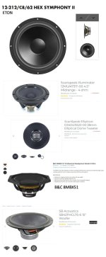
I bought all of this frontend sets and realise, that I wont use them.
So the 4 mentioned, Scourge (109 €) / Marauder (149 €) / Dreadnought (149 €)) / Bulwark (115 €) are for sale.
I had to pay for the sets, for shipping and customs.
Nevertheless I will sell for the prices they were offered in the diyAudio store.
Inside Germany, I will give them away without charging for PayPal or shipping,
In Europe I have to charge for the shipping because it may be expensive.
And I guess, worldwide shipping makes no sense.
The sets are untouched, I only oppened the package to check the sets. Thats why I didn't take pictures.
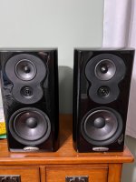
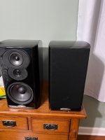
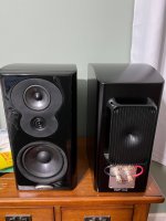
I have a pair of these black Polk LSIM 703 speakers, beautiful , heavy cabinets,
collecting dust , literally never used, one speaker was opened so I can see the crossover components for any possible "upgrades".
Shipping will be expensive, maybe someone from Chicago area would be interested.
I am original owner, bought them a couple of years back and I don't have the boxes anymore.
PM if interested.
Thanks
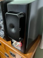
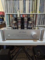
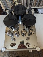
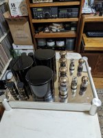
Excellent condition amp I acquired in a trade for a pair of Acoustat Electrostatic speakers. I am awash in tube amps and this one as well as 4 others must go. (Ask my wife for details!) It's hooked up temporarily in my office and sounds pretty nice. It has LA Audio branded output tubes marked KT94 Denmark. Who knows what they really are. (Shuguang) As well as 6SN7's and 6SL7's. I don;t have the original box and it weighs a ton! Local buyer preferred but I will ship but it won't be cheap.
4 inputs, motorized volume control, and remote that controls volume and inputs. Remote and Tube Cage included but not in photos. Specs:
A-100R INTEGRATED TUBE AMPLIFIER With remote control ● Output power: 90W * 2 ● Frequency response: 10Hz-45k. Hz ● harmonic distortion: 0. 7% (1k. Hz) ● Input sensitivity: 300m. V ● input impedance: 100KΩ ● output impedance: 4Ω 、 8Ω ● Signal to noise ratio: 88d. B ● Input signal: 4 sets ● Tube Supplement: KT98 × 4. 6SN7 (6N8P) X2 6SL7 (6H9C) X2 ● power consumption: 390W ● Dimensions: 36 (W) x51 (D) x19 (H) cm ● weight: 20 kg.
Would really prefer local buyer but will ship. Unit is available to come and hear in Pacifica, CA I think it's a steal at the price. See what you think. Message me for details or to arrange a listen. SOLD!!!
I am in the process of a project converting some speakers to active and will power them with LM3886. The preamp/active crossover is complete but I have too much gain in that stage for the current sensitivity of my LM 3886 implementation which is standard datasheet stuff (gain around 20x). Am I safe to reduce this to 10x or will I encounter stability issues. Thanks. Martin
My ACA is playing very nicely with my original Hestia OB build. But I never added the woofer to the Hestias. Even so the base they do have is great. The original design called for a run of the mill10" unit amped separately and low passed at 90 Hz. I made my baffle shorter in height than plan and there is not enough room for a 10". Wondered if this 6" unit would do okay? It would have to roll off clean at the bottom ideally. I use these near field at moderate to low volume. If I add these they will be amped separately too.
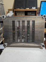
I've been working on a project on and off for a couple years. A while back I bought a Acurus DIA150 that was known to be broken and the issue undiagnosable. Well I traded some equipment for it and it cost me about 150 bucks so I figured why not.
He had taken it to a shop for repair but they told him, not repairable and then offered to buy it. he said no and just sat on it forever. so I found sabotage and was able to repair it.
well low and behold the amp sucked! overly bloated in the bass region and not an engaging sound at all. It was all in spec and I just didn't like it, so I figured I'd recreate in a fashion which pleased me.
So I began looking for a suitable amp module to put in the amp that looked stable and had a more balanced and engaging sound to it and settled on the JAT501. it was an online developed amp by a youtuber calling himself JohnAudioTech. really great online development of this amp module. lots of input and checking and double checking. well I was sold, love it. at 35-0-35 puts out about 80 watts. well I wanted an active design also, I'm not into passive setups so I hunted for a nice preamp module to match it. well I settled on a LMJ Preamp 9 module, gain 10 and I think the output impedance is 600 ohms. this preamp module has a great reputation for being really analog sounding, but the output impedance a bit too high for me.
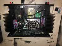
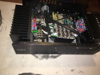
so in comes the Kuartlotron buffer. I had built a few of these buffers in stereo boards and saw my opportunity to implement it here. I saw the opportunity to patch the output of the LMJ Preamp 9 through a resistive ladder to about a gain of 3, which is a more appropriate gain for a amp module with a gain of 30db and feed it into the Kuartlotron buffer and then feed the amp.
I can just patch directly into the upper passive preamp section of the original amplifier. I'm also maintaining all the original function of the original amp. so it will have remote volume and input selection even remote on off.
at 4 ohms this amp puts out about 90 watts and at 8 ohms it's 50 watts. I have very efficient speakers and only need about 30 watts to get decent volume. I've made it a remote power supply and decided that i wanted to also add a few voltage rails to the supply that I didn't need for the build but at a future date I will use them to upgrade my dbx 4820 crossover.
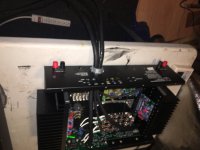
so the external rails are
+- 15 volts dc (alpha parallel regulated supply mounted to a larger heatsink then standard and capable of about 3 amps output.
22 volts ac for the LMJ Preamp 9
+- 35 volts dc for the amp modules (it will be a CLC type filter), the primary transformer is 500 va Antek AN52245 toroid.
+- 5 volts dc at 12 amps (that's the prefab aluminum device with T03's on top)
+- 9 volts for the Kuartlotron
SOLD - Modushop Dissipante 5U 500mm 10mm SILVER front panel - 3mm aluminium cover 6 rows of holes and Deluxe 5U Rear Panel
with Inner baseplate for Dissipante 500mm
This is the Big 500mm deep 5U NOT offered by DiyStore; Still in unopened box. attached original invoice.
Will eat original shipping cost AND Ship for free (48lbs) to US 48 states
$435.USD
Hello Nelson ! I have a question that only you can answer for sure . Which particular amplifier model did you get the best ? Some believe that the lightly armed Saracen CAS 2, which has the best resolution of the sound stage, others believe that the heavily armed knight Stasis 1 is better, and others last T 800 D . I am interested in exactly this kind of sound as a forceful manner of sound delivery, a purely American style, At the moment I have a three-block amplification Harman/Kardon pre 2500 and 2 power Harman/Kardon 2400 Signature Series and 2 pair Cerwin Vega DC 1515 , 40 th Anniversary designed by Marshall Buck . Thank you Nelson for answer .
I am replacing the laser pickup on my Marantz UD7007 and I can't find any jumper or solder bridge on my replacement that protects the pickup.
Does anyone know where the jumper is located? I've attached a photo. The other side also does not have a jumper.
I was wondering if there is design similar to St Helens for CHN110 and Vesuvius for CHR90 i.e. a top-firing vented box, but for Alpair 10.3 ?
I don't know it it is doable or not, but the design seems very interesting for modest spaces and near wall placement.
Got a Pioneer P3A Turntable in for trouble shooting. There are 3 diodes in the motor assembly , tabled D201, D202 and D203, they are imbedded within the coil structure. 2 of the three are shorted the working one measures 0.7V reverse voltage. The legend on the PCB is marked as two diodes in series. There's no markings on the parts them selves. Does any one have an idea what these parts are. Some resemblance to the SVT-2H parts made by Sanken?
I saw this video and it's the first time I saw a mechanical explanation of inductors, I think if everyone saw this, who was learning electronics, it would make amplifier design that much easier to grasp.
I have a valve amp (Acoustic Masterpiece) with, obviously, no remote control. I'm using the remote volume control of my network streamer (Marantz ND8006). This is not optimal because the variable output of the streamer is nowhere as good as the fixed output. I would dearly love a way of remote-controlling the volume of the amp so that I can switch to fixed output on the streamer.
I know this can be done with a stepper motor, control boards and code but I don't have the skills to put this together.
Does anyone know of a solution which doesn't need a lot of prior knowledge?
Searched but wasn't able to find info on this topic.
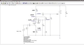
I am looking to build one of the Pass amp variations that uses relatively low power supply voltage. Something like 15 - 18 vac from the transformer.
I've located a surplus torrid that has a 230 volt primary and 30 volt secondary windings.
My question is, what happens if I run this transformer on 120 volt?
Can the transformer still deliver close to the rated current at half the voltage? Or will it burn up trying to do so?
I'm trying to figure out if I can simply buy big surplus transformers rated at 230 or 240 vac and have them be fine running at half voltage and yet still be able to provide a low impedance, big power reserve if needed?
If they do need to be de-rated, how much de-rating would be required?
Thanks in advance for any thoughts/advice you're willing to provide!
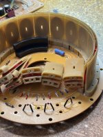
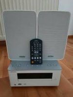
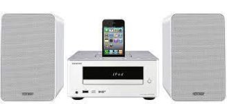
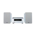
Hi folks, new to the forum - I have an Onkyo CS-245, got it for my daughter for her room - Everything works, CD, USB, Radio, Line, Speakers etc - Headphone jack working etc. No sound from the unit itself. It was spluttering intermittent sound but now completely no sound. Its been treated very well and not knocked at all. Should I bin it - its one of those things that's bugging me so much - I know its cheap, its not knowing what's wrong that's bugging me.
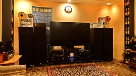
I am dismantling my large horns system to move to a different speaker after years of tweaking and joy. All in good to excellent conditions. I'll post pictures in the next hours and days. Shipping from Italy in sturdy and bomb proof packages. Open to reasonable offers. I will miss them all ... I know. I am already missing them. It took me years to find the TM1201, I will badly miss them. Very badly. I know I will regret. Someone please stop me from doing this.
TAD 4001 pair original diaphragms, recharged in 2011, they were unused spares when I purchased them and just saw domestic use. Note one pin retaining the cold terminal of one driver is missing so I just plugged in a piece of solid core wire (terminal is complete with spring and cap and fully working ... to lazy to fit a better pin). No original boxes.
ASK 3200 euro + shipping from Italy
TAD 2001 pair original diaphragms, recharged in 2011, bought them lightly used. No defects.
ASK 2400 euro + shipping from Italy
TAD TM1201 pair bought new in box, these are super super super rare and perfect for horn loading and I used them with a large 1mt horn. Note one driver has a very minimal sign on the cone, nothing serious. Original boxes. LOVELY!!!
ASK 2800 1950 euro + shipping from Italy
TAD 1603 pair in excellent shape. They were also spares when I purchased them so look perfect. No defects. No original boxes.
ASk 1400 euro + shipping from Italy
Autotech large tractrix 100Hz horn glossy white
wood flange, mouth is 100cm, throat good for >10" drivers, flange is drilled for TAD TM1201 but there is plenty of room for a larger drilling, gelcoat is perfect, you need to drill for your installation and plaster the existing holes and some fresh paint would make them really shine. overall in great conditions 1200 1000 euro + shipping from Italy (they were kind of 800each at that time)
Autotech IWATA 300 glossy white pair black metal flange for 2" drivers, no defect/scratches maybe you could consider to repaint the external but they actually look good as they are
900 600 euro + shipping from Italy
Autotech small tractrix 1kHz glossy black metal flange for 1" driver, do defects
200 100 euro + shipping from Italy
A very convenient supporting system for 2" drivers and horns powder coated in grey. Made of steel tubes and curved steel plate all professionally welded and machined. You can bolt it on a larger woofer box, two sets of tubes for different heights over the speaker box. Includes also supports for (driver) tweeters. Lower leg and base not included (see the very last pic), just the tubes and driver supports
150 euro + shipping from Italy (it costed me 400 or maybe even more)
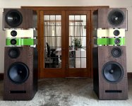
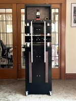
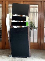
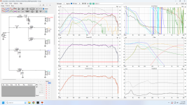
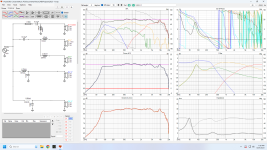
Years ago, I was inspired by the look of the Focal Grand Utopia speakers. I wanted to make my own and had a plan to build a 3 box, 3 driver version. I soon found out that I couldn’t cover the low end properly with one driver and so the design became 4 boxes. The plan was one box each year and I nearly hit it but finalizing the crossover design took a lot of time. In that time, I noticed an area in the mids that needed some reinforcing, so I added the 8” driver in its own sealed chamber. The 15” driver is powered by its own class D amp which is why I show the crossover with and without it connected. In the last 2 months I made a big push to finalize them and 7 years after I started them, they are finally finished.
How do they sound? Incredible. Unless I’m standing 3 feet in front of one of the speakers they sonically disappear and stereo image up there with the best of them. I finally got them in the listening room and now it’s time for some music and something else…
The pictures were not taken in the listening room I just needed some sun light.
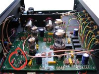
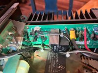
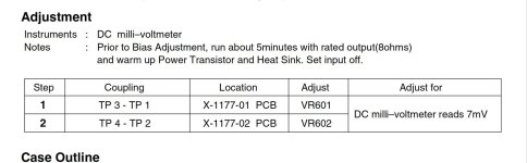
I recently purchased a used Rotel RB1080. Its in good working order, but i did some advance prep, just to get to know in general the topology and how it worked. I was able to find a service manual, and after cleaning up a bit, decided to check the bias.
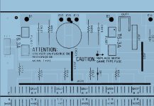
I found that my channel boards had a pretty different layout than the service manual, so was a little reticent to get too into it. I do a decent amount of building, but mostly studio audio and guitar amps, and mostly tube designs. I can read a schematic and have enough transistor knowledge to diagnose fundamental problems, but don't have a lot of experience in the HIFI world.
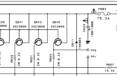
I've attached some info from the manual as well as a pic of the left channel front end. There should be two test points, TP1 and TP3 on the upper left corner. On mine they are not there. There is a resistor, R653(.22r) that parallels what should be TP1 and TP3, so I am assuming that should be the right place to test. On the PCB there is marking for TP1 right above this resistor with a line to either side of the resistor.
When I hooked my meter up to either side of R653, I got 3.5mV on both channels. I found that strange, and wonder if there was some reason it was biased to this as opposed to 7mV. I went ahead and biased both sides to 7mV. Amp sounds good, but I don't have a way of testing whether it's operating correctly.
I emailed Rotel with the serial number to see if they had a more accurate service manual with proper layout, but thought it might be worth posting here as well.
Im working on a Mosconi 5/30 thats going into protect. The PS runs for about 3 seconds and then shuts off. Im finding the Class-D section, Ch5; may be the culprit. Sometimes I see drive signal on the gate of some of the fets - and this drive signal reveals the falling edge not operating correctly. Its like the pull-down transistor may not be operational as the drive slopes instead of squares down. Other times the drive signal just has straight DC on it.
If I probe CH5 output terminals; sometimes the amp will try and stay powered on at 1.2A draw but its not stable enough to keep testing.
The parts in this amp are a bit foreign to me. I took this amp in thinking and hoping one of the ClassAB channels were the culprit and that turned out to not be the case.
Ive got this one which partially works, but LF and RR channels have 0.9vDC on them. The other two channels work. On the PCB, only half the LEDs are lighting up indicating those channels are not coming online. I removed the pre-amp board to help service the amp without having the ribbon cables flopping around and the amp still powers with only half the LEDs lit near the drivers away from the heat sync.
Is a schematic floating around for these style amps?
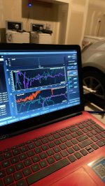
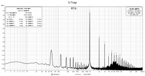
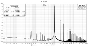
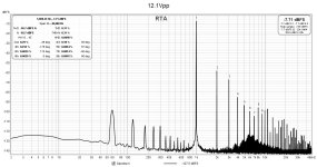
So, I made some FIRs for every speaker. I have just finished a tune where I used the time of flight removal , the “find” feature in smaart only on the HF drivers.
Then I aligned each lower frequencies to the time of flight from the Hf.
Before I would do tape measurement distance then use find and then convolve to that.
Now, I used signal delay and off the HF “find” have removed as much phase as possible, then convolve to that…
Both ways yield similar results. Which one is superior? It’s close to tape distances but not quite, I noticed also a can convolve out signal delay, if I used a different delay for the speaker I can convolve the wraps and make it the correct delay… weird
Any insight on this subject is helpful. How exactly does this stuff work
I have unequal path lengths and my room is a metal box and I sit in the corner.
One amplifier channel has much more which noise and some crackling compared with the other channel. My intuition, which can be wrong, tells me that since the bases of the differential pair are the most sensitive parts, the crackling and stronger noise might be generated by some component connected to the differential pair bases. The are two electrolytic capacitors, one on the inverting side and the other on the non-inverting part. One is quite large, 2200uF and the other an AC blocking capacitor of only 10uF.
Do common electrolytic capacitors cause white noise? I am suspecting a capacitor might be the culprit. I am also suspecting the differential pair might be from different batches, and hence, might not be matched.
Hi all. I have 8 1578 and 8 1579 tubes. All were got at least 10 years ago (or more, I do not remember it) for building MOSKIDO amplifier, but never was done. So, these tubes are as I purchased. These tubes never has been connected to any circuit, at least for me. And I do not measure them never.
Price is 80 eur + shipping + paypal fees for two 1578 and two 1579 tubes.
I was looking into buying classic electrostatic speakers and noticed that the listings are full of Audiostatics, Quads, Martin Logans that either already had their foils replaced or are sold as in need of foil replacement, and there are companies in Germany ans Switzerland offering to do this. At the same time, I find rarely anything here on diyaudio.
So if a foil starts sagging, developing folds, crumbling or having a non-uniform metallization, it is clear you need to change it. At the same time, there are few pictures of such foils. I also read one the pages of one such company offering overhauls that there is a gradual loss of sensitivity due to electro-corrosion, cigarette smoke, dust, animal hairs.
So, in a non-smoking home and without obvious visible flaws in the foil, is this really a thing or just good marketing by repair shops?
I can imagine audiophiles worrying about foil maintenance and I have read many German forum posts where owner state how much better their speakers sound after foil replacement. There probably is space for wishful thinking.
A gradual loss of sensitivity, especially if it does not change the frequency response, may be hard to verify without measurement equipment and a reference, and it is not particularly worrysome (turn up the volume or the stator voltage).
It is interesting to know what members of this forum use as music players.
I use a Raspberry Pi with a monitor and keyboard. The music is played through an IQAudIO card. I should think there are better options than this and sharing such knowledge should be beneficial to all forum members.
I'm working on a 3 way speaker design and found a neat small dual coil subwoofer (https://www.daytonaudio.com/product...-mmag-extended-range-subwoofer-4-ohm-per-coil) for the low end speaker. I wanted to try using one coil to cancel out the nonlinearities of the other. To do this, I would use a transformer to act as a comparator, then reverse the polarity to the second coil, thereby acting as an error signal. Is this a feasible way to use a dual coil subwoofer? If so:
1) what kind of transformer should I use?
2) would I need to power both coils, or just treat both of them as part of the same load?
Folks, I need your advice: is LASE 12 a direct replacement for EVM 12L? If not, how close are the specs? If not, what other 12" driver would be close enough to replace the venerable EVM 12L in a front loaded horn? Thanks to all that responded.
Is there anybody that can help me with copies of the following articles? I would very much appreciate it, thanks!
1. G. Galo, "Pooge-5: Rite of Passage for the DAC960, Parts I and II," (Audio Amateur - 2/92, 3/92).
2. G. Galo, "Pooge 5.5: More DAC960 Modifications," (Audio Amateur - 1/94)
I have two Edcor GXSE10-8-8K single ended tranny on a decaware amp. One channel is very quiet and the other is fine. When I reverse the output trannies the quite side follows the output tranny. Can I conclude a bad tranny
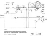
I'm trying to analyze the crossover network of ADS L1530 speakers. The schematic is posted on attached.
I calculated back the low-pass filter of the woofers, via online calculator, and found the crossover point to be around 500 Hz with Q of 0.33. This is not unusual because the active crossover, the ADS C2000 which was built for L1530, also have this characteristic in its selectable programs.
However, it's surprising that the high-pass section of the 2" midrange dome was only first-order, most ADS speakers I found usually having second-order slopes. Anyway, the problem is, as can be seen, the first-order high-pass of the midrange is formed by a single 10uF capacitor. By looking at first-order crossover table, it indicated that this filter is having crossover point at around 2.5 kHz! (with 6 Ohms midrange driver)
The question is, did I use the table or online calculator wrong, because I think there was too huge gap between the drivers -- about 5 times? I, actually, found the gap about 1.5-2.5 times in general crossover networks, but this is 5 times! What's your opinion?
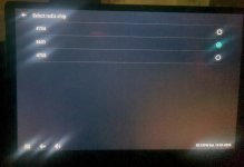
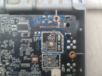
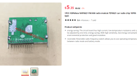
please i have this car multimedia system and i am only able to receive FM stations , so i am interested to add external tuner to be able to receive AM stations
from device software radio options i realized it can operate by si4754/4755 module ... by looking to board i could find these pinouts for si4755/54 but unfortunately i can not find a full module that can be directly soldered to radio board and i thought about adding any other module that do the job regarding sound quality >>> so my question is can i simply get one of available radio tuner modules and directly solder to board ? like tda 7703 or nxp 6621 nxp 668X ?
anyway is that simply possible ?
i'll attach some photos hoping that some one could help .. thank you very much
Hello, I have a problem with my Sony 700ES. Well, more than one.
1- Red power lamp stays ON and does not switch to green even after relays seem to engage (this thing is full of relays, not just for the output connections…)
2- attenuator seems to leak some signal on either channel at both ends of run. i.e.: all down some faint signal on the right channel isntead of zero, the opposite at max volume (tried the later with damping engaged and no signal input …)
3- the channels are altogether slightly unbalanced (R quieter and hollower, L fuller and louder) and possibly slightly distorting at times.
I downloaded several of the service manuals available online but they're not really usable (especially because all the voltage ratings on the schematics were originally in red ink and kind of disappeared in copied/scanned black and white images in pdf's.
Cheers again everybody, long time away. And got some time on my hands here.
Started a solid project several years ago. So Im searching some guidance on active filters/DSP. Before I continue.
Available toys :
Source :
Computer
Amps :
B&O ASP1000 4pcs
B&O ASP250 8pcs
McIntosh MC501 2pcs
McIntosh C50 pre
Speakers :
18Inch No-name Sub (Recommended from thrusted source)
12+12 mid bass Hi-Vi research D5.8
4+4 mids Hi-Vi research F5Ba/W5a
4+4 tweeters Hi-Vi research RT1.3
Active filter : MAIN QUESTION.
Consider MiniDSP Flex HTx with 8 balanced outputs. Sub/Mid-bass/Mid/Tweeter.
Im aiming for any dsp or filter within max 2-3K. To serve the rest of the setup decently.
Most likely also need a proper audiocard for my laptop. But the DAC in my C50 is quite OK.
Part list is a result of an ongoing hobby for a while.
Im not used to active setups at all. So therefore.
Any advice would be appreciated. If possible with info provided.
And yes, I plan to use 6+6 midbass/4 mids/4 tweeters/1 sub in each speaker. In 4 separate cabinets each. 12 midbass on top of each other. 4 mids and 4 tweeters in listening height on each side. Building in progress ;-)
I am rebuilding an old TAC Scorpion mixing console power supply - full re-cap and new volt. regulators.
While working, I noticed these resistors and thought I would go ahead and measure their values.
The schematic I found lists R3, R4, and R5 as 1 Ohm, 2.5 Watt. That schematic is located here: TAC PSU Schematic. (a note about this - my PCB is labeled JP294B on the underside and other than these resistor values, I haven't found a difference between my board and that schematic)
Anyway, all three of the above resistors test out at .5 Ohm. If I have the correct schematic, that is wrong.
Additionally, I noticed a slight discoloration on the underside of the PCB:
Are these guys in need of replacement? These are wirewound type, correct?
I bought a PCB that will replace the the dip 8 op amps in my Philips CD880 with an SRPP tube amplifier. The transformer and tube amp board will be mounted in an outboard chassis. The board holds it's own power supply and outputs left and right analogue signals to my preamp. Do I need to connect the ground in my CD player to the ground on the PCB? Neither the CD player or tube PCB connects to earth ground.
I've got a bunch of LD1014Ds that are looking for electrons so I have been thinking about more ways to keep them happy. I'm still working on my Variation of Zen Variations #9 amp, but I had an itch that needed scratching. I have been thinking about an LU1014D preamp off and on for a while, and recently the idea reached critical mass.
I fired up LTspice and sticking with the cascode approach and inductor loading, I played around with different power supply voltages and operating points. High voltage and low current seemed to work, although I encountered a problem with increasing gain above 10 kHz. The inductor loading was not working out.
I replaced the inductor with a resistor and that smoothed out the frequency response. I ended up with LD1014D Vds of 2.0V and current of 11mA.
The next issue is the high output impedance, around 3.5 kohm. That can be handled with a output buffer, so maybe not such a big deal.
To test this idea, I modified my Zen Variation #9 circuit, hooked it up to my lab power supply and ran some measurements. The DC voltages were not too far off from the simulations, and the distortion measurements were in the same ballpark. I did not optimize the LD1014D operating point by trying different source resistances, so the results can probably be improved.
I ended up with a V+ of 60V because that's the maximum output of my lab power supply. My next iteration will be to build a 120V-140V power supply for further testing. LTspice simulations show that better results may be possible with higher voltages.
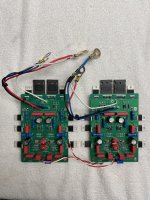
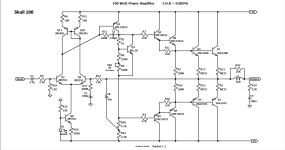
I am replacing some faulty output transistors and while the new transistors are spec’d equal or better than the originals. They are smaller in physical size. It was recommended that I add some output transistors as there is plenty of room on the heat sink just to give the output transistors an easier time I haven’t had to do this before, but I like the idea of it, as it gives me a new method to learn. The amplifier is a class H design, and here is a portion of the schematic for the outputs.
I have the collector wired directly in parallel with the other collectors. The emitter going to an additional emitter resistor (.22 ohm or .1)which then ties to where the other emitter resistors go. The base connects to a resistor (2.2 ohm) and then the other side of that resistor connects to where the other base resistors are.
Is the appropriate way in adding transistors? There are two output sections for each channel and each section uses two pairs of outputs. I would be increasing it to three pairs per section, a total of six pairs per channel. Thank you