I've got a bunch of LD1014Ds that are looking for electrons so I have been thinking about more ways to keep them happy. I'm still working on my Variation of Zen Variations #9 amp, but I had an itch that needed scratching. I have been thinking about an LU1014D preamp off and on for a while, and recently the idea reached critical mass.
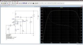
I fired up LTspice and sticking with the cascode approach and inductor loading, I played around with different power supply voltages and operating points. High voltage and low current seemed to work, although I encountered a problem with increasing gain above 10 kHz. The inductor loading was not working out.
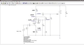
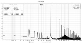
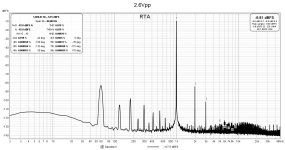
I replaced the inductor with a resistor and that smoothed out the frequency response. I ended up with LD1014D Vds of 2.0V and current of 11mA.
The next issue is the high output impedance, around 3.5 kohm. That can be handled with a output buffer, so maybe not such a big deal.
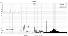
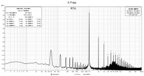
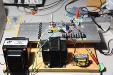
To test this idea, I modified my Zen Variation #9 circuit, hooked it up to my lab power supply and ran some measurements. The DC voltages were not too far off from the simulations, and the distortion measurements were in the same ballpark. I did not optimize the LD1014D operating point by trying different source resistances, so the results can probably be improved.
I ended up with a V+ of 60V because that's the maximum output of my lab power supply. My next iteration will be to build a 120V-140V power supply for further testing. LTspice simulations show that better results may be possible with higher voltages.
I fired up LTspice and sticking with the cascode approach and inductor loading, I played around with different power supply voltages and operating points. High voltage and low current seemed to work, although I encountered a problem with increasing gain above 10 kHz. The inductor loading was not working out.
I replaced the inductor with a resistor and that smoothed out the frequency response. I ended up with LD1014D Vds of 2.0V and current of 11mA.
The next issue is the high output impedance, around 3.5 kohm. That can be handled with a output buffer, so maybe not such a big deal.
To test this idea, I modified my Zen Variation #9 circuit, hooked it up to my lab power supply and ran some measurements. The DC voltages were not too far off from the simulations, and the distortion measurements were in the same ballpark. I did not optimize the LD1014D operating point by trying different source resistances, so the results can probably be improved.
I ended up with a V+ of 60V because that's the maximum output of my lab power supply. My next iteration will be to build a 120V-140V power supply for further testing. LTspice simulations show that better results may be possible with higher voltages.
Attachments
Last edited:

I remembered that I have some high inductance Hammond chokes somewhere which could be suitable as load for a high output impedance amp. These Hammond 156C inductors are rated at 150H at 8 mA and have a DC resistance of 3700 ohms. I could replace the 4.7k ohm load resistor with a Hammond 156C and the DC operating point would not change much.
So, I made the change and ran some tests. Distortion dropped considerably which was no surprise, and gain went up. Again, no surprise. Distortion dropped to about 1/3 of the resistor loaded circuit and gain increased to about 15x.
I tweaked the operating point a bit, and ended up with the LD1014D Vds = 2.48V and 8.5mA. The voltage after the inductor was about 25V.
Now, 150H of inductance is overkill, so a practical inductor design could be to use a Hammond 157G, which is rated at 30H at 40ma with 595 ohms resistance. The inductive reactance of 30H is about 3.8k ohms at 20 Hz, 4.7k ohms at 25 Hz, and about 190k ohms at 1000 Hz. The inductance is a bit low for 20Hz, but testing may prove otherwise. Or, it might be a good compromise.
At 8.5 mA, the voltage drop across the Hammond 157G (0.085 x 595) would be 5V, so the power supply voltage can be reduced from 60V to (25V +5V) = 30V.
One issue with an inductor, though, is the higher gain. Although, even with the resistor load, the gain is quite high already. Some negative feedback would help and it would also reduce the output impedance. Something to test.
Attachments

Another set of inductors emerged out of my memory banks. These are a pair of chokes wound by the late Mike LeFevre of Magnequest fame. I had used them in a pair of parafeed 45 SET tube amps. These amps were just breadboarded on pieces of wood so I dismantled them when I discovered VFETs. I've already re-used the interstage transformers in my 2SJ28/2SK182ES transformer coupled amps.
I couldn't remember the inductance of the chokes but they are rated for 60 mA and have DC resistance of 290 ohms. I connected one of the chokes in series with a 100k ohm resistor and with a variable frequency oscillator, determined that at 345 Hz, the choke's reactance equaled 100k ohms. That works out to an inductance of 47H. This is with no DC, so the value may vary with current, although in this preamp test, the current is only about 9 mA.
Any any rate, I threw it into the preamp circuit, tweaked the cascode a bit and made some measurements. The DC voltages actually matched the LTspice simulation quite well.
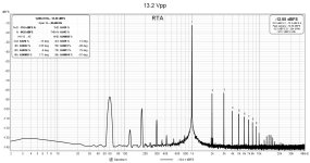
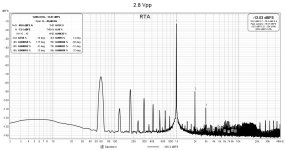
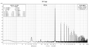
In terms of performance, distortion at low output is about the same as the small Hammond, but definitely an improvement at 12Vpp. I also upped the output to 34Vpp and that produced a THD of about 0.5%.
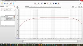
Frequency response was down about 1 dB at 20 Hz and about 0.5 dB at 20 kHz.
I modeled the output impedance in LTspice and the calculations show about 6.5k ohms. I will perform a measurement on the actual preamp to see what it is for real. However, I don't expect a huge difference since the low current LD1014D operating point is in the area of the characteristic curves where they are just starting to bend upwards.
I've included a photo showing a Hammond 193U and a 156C along side the Magnequest choke for comparison. The Magnequests are not small.
I couldn't remember the inductance of the chokes but they are rated for 60 mA and have DC resistance of 290 ohms. I connected one of the chokes in series with a 100k ohm resistor and with a variable frequency oscillator, determined that at 345 Hz, the choke's reactance equaled 100k ohms. That works out to an inductance of 47H. This is with no DC, so the value may vary with current, although in this preamp test, the current is only about 9 mA.
Any any rate, I threw it into the preamp circuit, tweaked the cascode a bit and made some measurements. The DC voltages actually matched the LTspice simulation quite well.
In terms of performance, distortion at low output is about the same as the small Hammond, but definitely an improvement at 12Vpp. I also upped the output to 34Vpp and that produced a THD of about 0.5%.
Frequency response was down about 1 dB at 20 Hz and about 0.5 dB at 20 kHz.
I modeled the output impedance in LTspice and the calculations show about 6.5k ohms. I will perform a measurement on the actual preamp to see what it is for real. However, I don't expect a huge difference since the low current LD1014D operating point is in the area of the characteristic curves where they are just starting to bend upwards.
I've included a photo showing a Hammond 193U and a 156C along side the Magnequest choke for comparison. The Magnequests are not small.
Attachments


I assume there is some wiggle room with that 7.16v at the gate of M1
so could you just use a 9V battery instead of that volage devider and
220uf cap. After all arn't batterys much quieter than using a voltage
devider and a cap.
so could you just use a 9V battery instead of that volage devider and
220uf cap. After all arn't batterys much quieter than using a voltage
devider and a cap.
There is great variation among the Lovoltech JFETs and because the JFET and MOSFET work together in the cascode, the 7V at the MOSFET gate in my implementation may not work for other LU1014Ds. R9 is a variable resistor which is part of the voltage divider to adjust the MOSFET gate voltage which varies the voltage at the MOSFET source /JFET drain. The operating point of the JFET is determined by this voltage and the source resistor self bias voltage. The MOSFET gate voltage needs to be determined by testing as the operation of the MOSFET and JFET are intertwined.
In any event, the difference between 9V and 7.2V at the MOSFET gate will change the operating points of the MOSFET and JFET enough that the parameters of the cascode will be quite different. The LU1014D operates with a Vds of 2 to 3 volts, so a variation of a couple of volts is huge.
You can always substitute a battery after you get the circuit working and see if there is any improvement in noise.
I got around to measuring the output impedance of the Magnequest choke loaded version of the preamp and it came out at 4.7k ohm. This is a little bit lower than the 6.5k ohm predicted by LTspice.
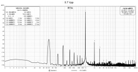
In the quest to lower the output impedance, I incorporated a bit of negative feedback. I added a 2.4k ohm resistor to the JFET input and moved the ground end of the 47.5k ohm gate resistor to the preamp output. This lowered the overall gain to 9x (19.1 dB) and the output impedance dropped to 1.2k ohms.
I had rechecked the gain prior to adding feedback and measured it at 19x (25.6 dB) . This translates into (25.6 dB - 19.1 dB) = 6.5 dB of negative feedback in the new configuration.
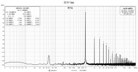
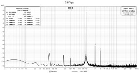
With negative feedback added, I made some distortion and frequency response measurements. THD at 2.8 Vpp and 5.6 Vpp dropped significantly and there doesn't appear to be much increase in high order harmonics. Distortion at 34 Vpp output also dropped by about one-half. Frequency response at 20 Hz improved to about 0.5 dB down.
I'm going to hook this version of the preamp to my LD1014D choke loaded source follower amp and make some measurements. The goal is to combine this preamp with the output stage to make an LD1014D/LD1014D amp that can be driven by a low output preamp.
In the quest to lower the output impedance, I incorporated a bit of negative feedback. I added a 2.4k ohm resistor to the JFET input and moved the ground end of the 47.5k ohm gate resistor to the preamp output. This lowered the overall gain to 9x (19.1 dB) and the output impedance dropped to 1.2k ohms.
I had rechecked the gain prior to adding feedback and measured it at 19x (25.6 dB) . This translates into (25.6 dB - 19.1 dB) = 6.5 dB of negative feedback in the new configuration.
With negative feedback added, I made some distortion and frequency response measurements. THD at 2.8 Vpp and 5.6 Vpp dropped significantly and there doesn't appear to be much increase in high order harmonics. Distortion at 34 Vpp output also dropped by about one-half. Frequency response at 20 Hz improved to about 0.5 dB down.
I'm going to hook this version of the preamp to my LD1014D choke loaded source follower amp and make some measurements. The goal is to combine this preamp with the output stage to make an LD1014D/LD1014D amp that can be driven by a low output preamp.
Attachments


Lately I have been listening to this prototype preamp feeding the left channel of my LU1014D follower amp. The power amp drives my Quad ESL speakers. I posted about this in my thread - https://www.diyaudio.com/community/...ke-loaded-source-follower.400792/post-7528722
I was concerned about the preamp's higher output impedance affecting the amp's frequency response, but it was not a big problem. All in all, I'm happy enough with the results that I've been working on a PCB for the preamp over the last few days, and it's almost ready.
I was concerned about the preamp's higher output impedance affecting the amp's frequency response, but it was not a big problem. All in all, I'm happy enough with the results that I've been working on a PCB for the preamp over the last few days, and it's almost ready.
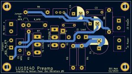
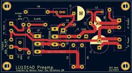
I've been working on the PCB on KiCad for the last few days, and after quite a few "I think I'm done" moments, I think I'm done.
I have tried to build options into the PCB: negative feedback or not; resistor or inductor load; power supply decoupling capacitor footprint to accomodate some 63V electrolytics; parallel resistors on LU1014D source to allow bias adjustment.
The MOSFET dissipates about 2 watts so a small heatsink is required. There is enough room around the MOSFET for this. I am going to try using a small aluminum plate (3cm x 5cm) to see if that is sufficient for cooling. The LU1014D mounted on the aluminum breakout PCB is fine without additional heatsinking.
I will be generating Gerber files and ordering some boards from JLCPCB probably tomorrow. The boards are 50mm x 90mm so with slow shipping, they should be quite cheap.
I intend to provide the Gerber files to interested persons. Until I actually receive the boards, populate, and test them, I don't know how they will perform. However, if anyone doesn't want to wait, I can provide them with the Gerbers now.
Attachments


The preamp PCBs are in Canada, so they should be in my hot little hands in the next few days. Pretty good service for US $4.00 for five boards from JLCPCB. Including postage.
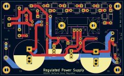
Meanwhile, I created a PCB for a regulated power supply which I just submitted to JLCPCB. Again $4.00 for five boards.
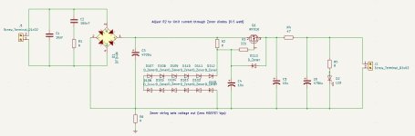
The power supply is a simple zener regulator with a MOSFET source follower buffer. I've made the circuit board to accommodate electrolytic capacitors up to 25mm diameter so input voltages up to 180V or so can be used. There is also room around the MOSFET for a heatsink. This regulator circuit is the same as the one Michael Rothacher used for his LuminAria, and so this design can be used for a wide range of voltages.
I have included room for 12 zener diodes to set the voltage. This should be enough so lower voltage zeners can be used to minimize noise. R2 drops the input voltage to the value of the zener string and it can be sized so the current through it and the zeners is around 7-8 mA. Power dissipations of the resistor, zeners, and MOSFET should be considered. The output voltage will be about 5V (Vgs of MOSFET) lower than the zener regulated voltage at the MOSFET gate.
Meanwhile, I created a PCB for a regulated power supply which I just submitted to JLCPCB. Again $4.00 for five boards.
The power supply is a simple zener regulator with a MOSFET source follower buffer. I've made the circuit board to accommodate electrolytic capacitors up to 25mm diameter so input voltages up to 180V or so can be used. There is also room around the MOSFET for a heatsink. This regulator circuit is the same as the one Michael Rothacher used for his LuminAria, and so this design can be used for a wide range of voltages.
I have included room for 12 zener diodes to set the voltage. This should be enough so lower voltage zeners can be used to minimize noise. R2 drops the input voltage to the value of the zener string and it can be sized so the current through it and the zeners is around 7-8 mA. Power dissipations of the resistor, zeners, and MOSFET should be considered. The output voltage will be about 5V (Vgs of MOSFET) lower than the zener regulated voltage at the MOSFET gate.
Attachments
Long ago in The Audio Amature I saw a guy used a CCS and
a resistor instead of a zener to eleminate any zener noise. Or in
view of the low curent you will require what about a voltage
regulator tube not only are they super quiet but have a nice glow !
Sort of off topic but doesn't part of the voltage gain of the circuite
come from the mosfet. If that's the case about how much of the gain
comes from the jfet.
Merry Christmass
When I was into tubes, I used 0D4 regulator tubes. They did have a nice, soft purple glow.
In terms of voltage gain in the cascode, the common source JFET outputs into the common gate MOSFET stage. The input at the source of the MOSFET has low impedance so the gain of the JFET is not maximized. The MOSFET does contribute to the gain.
It's easy to simulate in LTspice to show this, and I will post some results when I have access to my LTspice computer in a couple of days.
I finally got around to exploring the voltage gain of various parts of the cascode. I did this both in LTspice and in the actual circuit itself. In general, the LTspice results agreed with the measured values of the test circuit.
The bottom line is, the voltage gain of the common source JFET is significantly below 1, with all the gain coming from the MOSFET common gate stage. The key is the low common gate input resistance which is the load of the JFET. This resistance is approximately 1/transconductance which works out to less than 1 ohm.
Here are my measurements for a 1 kHz input signal into the cascode:
Input = 600 mVpp
JFET gate = 340 mVpp (due to negative feedback)
JFET drain / MOSFET source = 40 mVpp
Output (MOSFET drain) = 6.0 Vpp
Gains:
JFET = 40 mV / 340 mV = 0.12
MOSFET = 6.0 / 0.040 = 150
I have a good ZV9 I built, in Pictures of your diy Pass amplifier post #904,
being fed by an old NAD 1700 preamp/tuner. I love the combo but the NAD is old and I have several LU1014D’s that might be just the ticket for this preamp. If it had sufficient voltage gain to drive an F4 or any other current gain amp I would already be ordering parts. More research on my part is in order. Please keep up the good work. That said I would gladly take 2 preamp boards and 2 power supply boards. Feel free to pm me with pricing and availability.
being fed by an old NAD 1700 preamp/tuner. I love the combo but the NAD is old and I have several LU1014D’s that might be just the ticket for this preamp. If it had sufficient voltage gain to drive an F4 or any other current gain amp I would already be ordering parts. More research on my part is in order. Please keep up the good work. That said I would gladly take 2 preamp boards and 2 power supply boards. Feel free to pm me with pricing and availability.
You can actually get JLCPCB to make and send you 5 pieces of each board for probably less than what I would have to pay in packaging and postage to send you the PCBs. Paying by credit card and not Paypal, and using the cheapest shipping, it costs US $3.50 for 5 boards. So, $7.00 for preamp and power supply boards, and you would have some left over.
After I receive, build, and test the boards, I can send you the Gerbers or some boards at cost of envelope and postage.
As for driving the F4, it may do the job. See post #7 for distortion numbers at various output voltages.
After I receive, build, and test the boards, I can send you the Gerbers or some boards at cost of envelope and postage.
As for driving the F4, it may do the job. See post #7 for distortion numbers at various output voltages.
Thank you, that sounds great. Kicad and I go way back so having the actual Gerber’s will work out great.
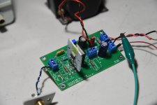
I visited my mail box and discovered a late Christmas present. JLCPCB came through with my preamp PCBs.
So, I disassembled my test prototype and populated a PCB with the parts. I don't have a small capacitor for the feedback loop, so that is not in place, and I used a 220 ohm resistor for the JFET source resistor. The prototype had an 180 ohm resistor, but there is room on the PCB for a parallel resistor to adjust the final value. The spot for the film capacitor to parallel the output electrolytic capacitor is also empty. I'm using this PCB for test purposes only, so I wasn't particular about some of the details.
I hooked up the finished PCB to my lab power supply, applied a 1 kHz input signal, and the oscilloscope showed a good output signal. I adjusted the cascode and measured voltages were correct.
It looks like the schematic to PCB process was successful.
Attachments


Fugly!
tried some TO220 as cascode?
in principle, part with lesser capacitances can do just some good
tried some TO220 as cascode?
in principle, part with lesser capacitances can do just some good
No, I haven't, ZM. As I was working on a cascoded power amp, I just modified it to work as a preamp. That's why I've got the IRFP240 there. It's overkill, but then I don't have to worry about heatsink.
I've got some IRF510 TO220 devices. I see that Ciss = 180pF compared to 2800pF for the IRFP240. Might have to try them. I'll see what LTspice thinks.
I've got some IRF510 TO220 devices. I see that Ciss = 180pF compared to 2800pF for the IRFP240. Might have to try them. I'll see what LTspice thinks.
- Home
- Amplifiers
- Pass Labs
- LU1014D Preamp