DIY CLD Plinth Design--A measured Approach

I've been investigating different ways of building a better turntable plinth. There appears to be a lot of myth and misconception surrounding the techniques used in proper plinth design, and not just from the DIY crowd. I did a lot of on-line research, but the best resource I found was this site:

http://qualia.webs.com/plinthbuilding.htm

He also posts at these sites as well as others:

plinth building - audio qualia
Lenco Reference :: Damping factors
audio qualia - Information


The author does a great job of explaining the physics behind a seemingly simple concept of building a supporting structure for your turntable's components and applies the necessary amount of scientific rigor to the problem, rather than guessing at the results or just hap-hazzardly combining materials that may look good, but produce specious results. I highly recommend anyone interested in the subject to read through his website, but the short version of it (if I may paraphrase and with apologies to Bryan) goes something like this:

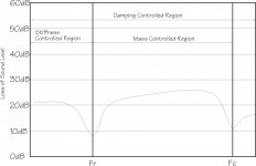
There are 3 areas of acoustic interest regarding the plinth, divided by 2 boundaries: One measured (resonant frequency) and one computed (critical frequency). All solid objects will have a resonant frequency (or multiple Fr) at which they will vibrate when excited properly. The critical frequency is computed and is affected by the density (P), thickness(h), Young's modulus (E) and Poisson's ratio (v) of the material: fc=[c^2*sqrt(12*P*(1-v^2)/E)]/(2*PI*h) (where c=speed of sound in air). The critical frequency is the frequency where the material becomes acoustically transparent. Vibrations that originate in the plinth (or a component such as a motor attached to the plinth) will propagate freely into other components and radiate sound into the air. Airborne vibrations at Fc or above, will freely enter the plinth and propagate into other components attached to the plinth.

Below the resonant frequency, vibrations are mainly controlled by the bending stiffness of the material. Between the Fr and Fc, mass loading mainly controls the vibrations and above Fc, only damping controls the vibrations, although damping has an effect across all 3 areas. Ideally, you want some spacing between Fr and Fc for mass loading to be effective; if Fc is at or below Fr, increasing mass will have no effect on vibration control. Increasing thickness lowers Fc and raises Fr, which are both undesirable, so you want a material which is thick enough to provide good stiffness, but not to thick that causes Fr and Fc to converge or cross. The ideal single material would be very dense, stiff (but not too stiff), thin and have good natural damping characteristics. Unfortunately, there doesn't seem to be a single material that hits every check box, so the next best thing is to combine materials into a layered construction.

The situation described above is valid for a plinth made of a single layer of homogenous material. It gets a little more complicated when you start to layer different materials. Finite Element Analysis may be the proper tool to analyze layered approaches, but simulators are only as good as the models you feed them and so far, I haven't found an adequate model for multilayer panels. I took a more empirical approach and measured/computed individual materials that seemed like good candidates, combined them in a number of ways and measured the composite results.

One of the most common approaches is to use a technique called Constrained Layer Damping or CLD. A number of mfrs claim to use CLD plinths, but technically, they aren't CLD. CLD uses two stiff outer layers that are attached to an inner damping layer via a visco-elastic layer between each section that dissipates the vibrations as heat when the layers flex. The VE layer needs to be elastic, but have high sheer strength and be thin enough not to create a "sprung" design. The author of the reference website explained it this way: If you hold a piece of glass between your fingers and strike it, it will ring. If you loosely place another piece of glass on top of it, the first layer will be damped and ring for a much shorter time. If you tightly bond both pieces of glass together, they act as a single layer of glass and will ring when struck again. I'm confused by some of the commercial designs that seem to ignore the basic premise of CLD design. Instead of a damping layer sandwiched between 2 stiff layers, with visco-elastic material between them, they have a stiff layer (aluminum) sandwiched between 2 damping layers (MDF or acrylic) with rigid glue holding them together, and fairly substantial hardware bolted through all three layers (feet, platter bearing, tone arm mount) that will reduce the isolation created by separate layers. ClearAudio does a good job of this using thin aluminum outer layers, with a thick layer of Panzerholz between them, which has excellent damping characteristics. VPI uses MDF-Aluminum-MDF which does not provide the optimum characteristics, and bolts the layers together as well as gluing them. When I eventually settled on the materials and construction that I wanted to use, I mounted the platter bearing and tone arm to the top stiff layer only, they are isolated from the damping layer and the bottom stiff layer. Likewise, the feet are attached to the bottom stiff layer only and isolated from the damping layer and top stiff layer. This provides maximum coupling between the platter and tonearm, but minimum coupling between the platter/tonearm and the outside world.

Attachments

  • Critical Frequency.jpg
    Critical Frequency.jpg
    110.6 KB · Views: 3,551

For Sale Bartolucci Plate Chokes

Hi,

I have Bartolucci plate chokes for sale. They were purchased maybe 10 years ago, if I remember correctly.

Model is FMPC 226.

Good thing I wrote that down because the web isn't online anymore.

They were rated at:
200H @20hz
DC current 20mA
Rdc 516R
Freq response 4Hz - 80kHz +-3dB

Price is 200€/pair!

If you have any question, don't hesitate to ask.

Attachments

  • IMG_20240327_041750.jpg
    IMG_20240327_041750.jpg
    341.1 KB · Views: 108
  • IMG_20240327_041807.jpg
    IMG_20240327_041807.jpg
    467.8 KB · Views: 90
  • IMG_20240327_041826.jpg
    IMG_20240327_041826.jpg
    392.3 KB · Views: 97
  • IMG_20240327_041859.jpg
    IMG_20240327_041859.jpg
    428.9 KB · Views: 99

Bipolar Mirage combined with dipole bass/subwoofer

Hello. I have Mirage OM6 speakers and are pleased with the big bipolar/omnipolar soundstage. Now I have the chance to buy OM8 very cheap. I think they use same tweeters and midranges so I can use them a spares. But I got another idea; what about using the top,skipping bass module and using open baffle in bass instead? Would this be totaly wrong combining two different solutions? Bipole top with dipole bass?

any audio BJT low noise but very high voltage?

I have a class-A small signal TIA challenge to be solved with BJTs.
From your experience, which transistor models are similar or better to the BC550 in noise figure, but much higher voltage VCE0?
Maximum input signal, for example, is 5mVp@1KHz delivered by a pickup coil. If I design for 80dB amplification, the output signal is already 50Vp which in class-A it requires VCE0>100V.
This is not a power amplifier, it is a preamp.
Which direction&part do you advise and recommend?

For Sale Salas UltraBIB v1.3, L Adapter and Reflektor-D power supply PCBs and actives

1x L-adaptor high current PCB $18
2x Salas SSLV 1.3 $25 each
2x Reflektor-D $18 each
Plus active devices 18 x measured PF5102 (measured at <7.5ma for $1 each) and 12x BC560C for Ubib, $18 (Setting UBIB for 5v needs the measured PF5102)

Free shipping in UK for the above, would prefer the equivalent in £. Can supply links to the build guides and original group buy.

Originally purchased from Teabag, brand new and unused.

Attachments

  • IMG_4774.jpeg
    IMG_4774.jpeg
    688.4 KB · Views: 106
  • IMG_4773.jpeg
    IMG_4773.jpeg
    782.5 KB · Views: 106
  • IMG_4772.jpeg
    IMG_4772.jpeg
    808.7 KB · Views: 113
  • IMG_4771.jpeg
    IMG_4771.jpeg
    815.6 KB · Views: 114

For Sale PCBs to build an active 2-way crossover, 4th order

I have a few PCBs to build an active 2-way crossover (4th order, Linkwitz transform in both LP and HP sections).
The schematic of the circuit and the PCBs are shown in the photos below.

The cost is 19 Euros for one PCB (shipping is included). For 2 pcbs, the cost is 33 Euros (shipping is included).

I will provide also the PCB assembly guide.

If you are interested send me a Private Message.

Attachments

  • 2-way active crossover schematic -1.png
    2-way active crossover schematic -1.png
    127.1 KB · Views: 1,302
  • 2-way active crossover.jpg
    2-way active crossover.jpg
    476.4 KB · Views: 1,288

NS1000M New Mid/high Crossover & Active Bass

Hi all,

I can see there’s a lot of experience of the NS1000M here, so maybe someone can help me?

I’ve just joined the club with a really nice lateish pair, and want to start tweeking them. I want to initially go active on the bass, and use a simplified crossover on the mid/tweeter. I will use an active crossover for bass to mid at 500hz LR 4th order, so don’t need a low pass on the mid. And I want a simple mid HP filter / tweeter LP filter, 2nd order, with no L pads.

So what is the consensus for cap and inductor values for what I want to do:

1) Stick with the Yamaha values as they are now?
2) Or is there a better crossover point to aim for? If so what are the values I need.

I’ll be using low power class A on the mid/high, and class D for the bass.

Cheers,

Jonathan

JBL BP1200.1

Hello all.

I have extensively repaired this amplifier and all is well and working good.

I was wondering if somone knows what VR102 the 5k pot is for on the board? The service manual does not mention adjustments.

In the parts description it is called volume? Does this need to be adjusted and how is the proper way. I have not moved it from the factory setting.

Markaudio: has anyone designed something like this?

I've been investigating MarkAudio drivers & I'm itching to try a design. It occurred to me that a 4" driver (like the inexpensive CHR-70) mated with a low cost high efficiency 6" or 8" bass driver could simultaneously achieve baffle step compensation & relieve the load on the 4" driver, when crossed over at the baffle step frequency. A double chamber bookshelf style box is required, no biggie. The crossover could be fairly simple too. Has anyone published a DIY design along these lines? Thanks in advance!

cheap UCD "500 watt" modules on eBay

Hello,

I'm just curoius to know if anybody has had any experience with these knockoff hypex modules:

https://www.ebay.com/itm/186177367845?var=694210321088

Just ordered one with this PSU to power it:

https://www.ebay.com/itm/375000352708

I know that people aren't going to like the chinese stuff, but just looking to see if anybody has had any success with these yet.

thanks and cheers.
  • Like
Reactions: Roby60

Can I Replace a Mechanical POT With A Digital One On My Delay Pedal?

Hi All,

I'm inventing something for the effects pedal market. As in distortion pedal, delay pedal etc. I know only a bit about electronics and circuitry. Engineers will help me later. For now I'm just trying to understand this:

Is it possible to remove any given pot from a pcb, as in the "Time Knob" on a delay pedal, and replace it with a digital means of parameter control?

If so, how?

Can the now empty points extruding from the pcb be connected to a DAC of some sort, thereby opening the possibility digital control?

I'm knew to this forum thing.. please be gentle. 🙂

Thanks in advance.

Pete

  • Locked
Cheap Rack Cases

I have the following brand-new rack cases in kit form for your audio/electronic projects at clear-out prices:
Item Case size Available Unit price
A. 2H x 12W x 7D inches 13 C$14.
B. 5 x 12 x 7 5 C$18
C. 3 x 17 x 12 10 C$20.
D. AL 3 x 17 x 12 19 C$30.
E. AL 4 x 17 x 12 11 C$35.

Note: All front panels are aluminum
AL=all aluminum ideal for your preamp project
All come with handles, hardware, and instruction
Shipping extra. Give me your address to work out the cost

Attachments

  • 20190713_120235.jpg
    20190713_120235.jpg
    219.4 KB · Views: 109

POE lighting and the new Class 4 digital electricity.

Is anyone following these areas? I've watched POE lighting gain popularity lately with server racks full of POE switches dedicated to lighting. Rated inherently safe @ <60V- 802.3bt (100w poe) and subject to Class 2 wiring standards (US, NEC). It feels like this could change the way a lot of wiring/lighting is handled. Then I ran across an article on Digital Electricity, packetized electricity at 200 or so packets per second with fault protection, also deemed inherently safe. With IEC/NEC approval, widespread adoption is likely on the horizon. I'll need the 2023 code on hand soon so will go ahead and pick it up to get at first hand look at the details. I'll dig up a link to an article I read a month or so ago. Interesting stuff.
So, anyone else seeing this? Anyone here actually planning on implementing it? New commercial projects might look a little different soon.
Cheers

Ortofon step-up transformer wiring

I am trying to hook up an Ortofon TU-20 transformer (it is the actual transformer in an Ortofon T20) and I am not sure how to connect.

Can someone guide me?

See attached pictures

The Ohm readings I get are

Wires Left side Right side
striped -red 0,6 ohm 0,6 ohm
striped-gray 0,66 kohm 0,66 kohm
red gray 0,66 kohm 0,68 kohm

There is no continuity between left and right side. The gray cable in the middle has no connection with any of the other wires, so I assume it is ground.

Attachments

  • IMG_0656.jpeg
    IMG_0656.jpeg
    777.9 KB · Views: 130
  • IMG_0657.jpeg
    IMG_0657.jpeg
    668.2 KB · Views: 122

Guides for diagnosing amp trouble? Niles Si-275, no output

Hi Solid state folks,
A Niles Si-275 has come into my possession. Its a great 2 channel amp that goes overlooked in used a lot of times. Sadly, this one powers on but does not have any sound output. Could anyone provide a brief checklist of things to go over with my DMM to try to locate the issue? I did a visual inspection and nothing looks burnt. The capacitors have some brown staining around some the bases, could be old glue?

I'm not an engineer but I am pretty capable, and know enough to not get myself electrocuted. I can post some photos of the inside if anyone's interested, its all discrete components, very nicely spaced out.

For Sale A pair of Focal Audiom 11 WX

I'm selling a pair of Focal Audiom 11 WX drivers, which are used but in perfect condition. I no longer have the original packaging, but I can assure you they will be packed securely. If needed, I can provide photos of the packaging process for your approval. You can find the technical specifications in the following link: Datasheet

The price is fixed at €1000 for the pair, payable via bank transfer. Shipping costs will be the responsibility of the buyer. I'm not interested in any material exchanges. Please feel free to reach out privately if you're interested.
  • Like
Reactions: Behruz

How to improve the quality of your sound: Practical guide to optimize your audio room

B0C1J2WRR9.01._SCLZZZZZZZ_SX500_.jpg

*** ✔️ THE BOOK THAT WILL HELP YOU GET THE MOST OUT OF YOUR SOUND SYSTEM ***This is the book you should read to learn how to optimize your room and achieve maximum performance from your audio system. It covers all the necessary knowledge so that, starting from scratch, any average enthusiast can reach a level of excellence. Anyone of us can achieve professional results, you just have to follow the step-by-step recipes.

THIS BOOK TEACHES YOU:

▶️ What are the basic concepts of sound and acoustics.
▶️ What are the advantages and disadvantages of different types of audio rooms.
▶️ How to create and condition an audio room from scratch.
▶️ How to measure, analyze, and treat noise.
▶️ How to optimally orient and position furniture, speakers, and the listening point in your room.
▶️ How to perform and analyze acoustic measurements.
▶️ How to perform passive conditioning based on temporal response.
▶️ How to perform passive conditioning based on frequency response.
▶️ How to use active components (equalizers, audio processors) to improve the sound of your system.
▶️ How to perform active listening to detect problems and verify improvements.

Available in the following Amazon stores:
https://www.amazon.com/dp/B0C1J2WRR9
https://www.amazon.co.uk/dp/B0C1J2WRR9
https://www.amazon.de/dp/B0C1J2WRR9
https://www.amazon.fr/dp/B0C1J2WRR9
https://www.amazon.es/dp/B0C1J2WRR9
https://www.amazon.it/dp/B0C1J2WRR9
https://www.amazon.nl/dp/B0C1J2WRR9?language=nl_NL
https://www.amazon.se/dp/B0C1J2WRR9
https://www.amazon.ca/dp/B0C1J2WRR9

Also available in Spanish:
61oKkJoo80L.jpg

Attachments

  • B0C1J2WRR9.01._SCLZZZZZZZ_SX500_.jpg
    B0C1J2WRR9.01._SCLZZZZZZZ_SX500_.jpg
    22.9 KB · Views: 93

Tarkus or not Tarkus?

Hi all,

The Tarkus seems to be still appreciated after 14 years of existance. I understant it is an relatvely inexpensive design and rock music oriented. Since i come from Harbeth, Audio Physic and Triangle land, I want to make shure the Tarkus is not a too fatiguing speaker (harsh, agressive, etc.).

I do want a rock speaker buy my old ears are fragile 😉

Can I have some feedback please.

Walter

Not so new member

I've been a member for a couple of years, but I've never been particularly active. The only thing I've built so far is an ACAmp. Future plans include the Biamp 6-24 Active Crossover, either another ACA or an Aleph J, and probably a tube preamp. I currently have a question posted on the Biamp Crossover thread to confirm capacitor selection before placing an order from DigiKey, but I'm still waiting for a response.

I look forward to getting more active on the forums and to meeting new folks. Thanks for having me!
  • Like
Reactions: stv

What position to place Peavey bass tube horizontal or vertical

I'm placing an old dj bass tube I made out of a 15" pro driver and a sonotube design app into my motorhome (so i can get throwed out of all the rv parks) and because we are remodeling it I'm building the interior around the tube . It is 4ft tall when standing if laid on its side it's 24"x24" and 48" long and the driver is ported on one end and the driver is placed at the other so my question is whether to stand it upright in a corner or on it's side on the floor ????? No bad answers cause we know that this is an opinion of personal result so just what would you do 8x20 room 8ft tall and not for outside sound just inside.

Choke Orientation

I am working on the orientation of the Power Transformer, Output Transformer and especially now the two chokes. I have determined the quietest relative positions of the PT to the OT but how do the chokes play into this? Should I energize the PT and position the chokes where they are the quietist of energize the chokes and listen at the OT? I also have a stand alone filament transformer I have to deal with, so many different pieces to fit together.
Thanks

Music Reference RM9 Mk.I schematic

Is there anyone who have the schematic for the RM9 Mk.I?
Made some new pcb for this one. Double sided and with 70um tracks. The silkscreen is marked with the resistor values I found on the old pcb but I`m not sure if they all were the original ones. Got 4 left so if anyone is interested I could sell for the actual cost.

Attachments

  • DSC_0424.jpg
    DSC_0424.jpg
    892.7 KB · Views: 1,083
  • DSC_0425.jpg
    DSC_0425.jpg
    609.7 KB · Views: 1,098
  • DSC_0427.jpg
    DSC_0427.jpg
    557.5 KB · Views: 926
  • DSC_0429.jpg
    DSC_0429.jpg
    967.7 KB · Views: 1,053

Luxman C120 a Phono Stage Input Capacitance

Can anybody confirm the input capacitance of the MM Phono stage of this pre-amp?

It’s not listed in the specs section of the service manual. The circuit diagram shows a 56pF capacitor to ground on the input stage but this sounds very low as I understand most phono stages are somewhere around 150-300 pF.

Does the input transistor contribute to extra capacitance in addition to the 56 pF in circuit? How much?

My phono cartridge specifies ideal capacitance of 400 pF, and allowing for typical 150 pF in the cabling, I need about 250 pF in the pre-amp.

Magnavox vintage field coil speakers - free for shipping costs

I have a pair of 10" or 12" (not sure) Magnavox vintage field coil speakers that I will sell for $35 which should cover the cost of shipping only. US only. I will remove from the plywood and bolt together to ship. There are no rips or tears in the cones. The transformer is included. The whizzer cone in the picture is not attached to the speaker but is included. I'm sorry but no refunds since I'm essentially giving away.

Maganox 1.JPG
Maganox 2.JPG
Magnaox 3.JPG

SBAcoustics SB17CRC sounds really nice!

20240323_132923.jpg


I have the SB26STCN 4ohm tweeter and SB17CRC carbon fiber 8ohm woofer in a small bookshelf setup, sealed box design of about 0.2cuft. I use the reference driver curves (frd/zma files I found online) and modeled a very simple crossover: just a 10uF and 2ohm resistor on the tweeter, and a 0.6mH and 10uF cap on the woofer. Tweeter is wired reverse polarity. No baffle step correction yet. I dont think I need it in my setup close to the wall.

I am quite impressed with these SB drivers. Compared to my Vienna Acoustics Bach speakers (1" Scanspeak dome tweeter and 17cm Seas woofer), these SBAcoustics drivers sound just as purely musical, but I feel like it removes a veil in the midrange nicely. And it has really good bass slam.

I even tried replacing the 17cm Seas driver in the VABachs with the SB17CRC. It was 2mm too big, but I buffered the cutout with foam tape and bolted it in. The tweeter was too bright, needed to be trimmed down, but wow, solid depth and slam in the 0.7cuft ported box. It would be an amazing upgrade if it just fit the existing cutout and the tweeter was padded down about 2-3db.

Next up is to source a measurement microphone and take some readings of in room performance, maybe further tweek the crossover. But I would be happy living as is with these speakers now.

Fun little project, and low barrier to entry. Highly recommended. Would do again!

Attachments

  • 20240322_181500.jpg
    20240322_181500.jpg
    283 KB · Views: 99

Zu Dwx

My current speakers have become the weak link in my system... So I was thinking of the Zu DWX. They get rave reviews and would cost $1,500 to my door. I have all the tools to build a published design and I would surely do so if I could get something comparable for $1,000 or less. Would need to live happily with an Amp Camp amp. MY current speakers are OB Hestias without the woofers and supported by a small sub. They are very good and excellent in the value department.
1000001090.jpg

For Sale HD Audio (of Surrey, England) Monoblocks

In excellent fully working condition
Very good cosmetic condition and in their original packaging.

These were made in Surrey UK I think in the early 90’s
Unfortunately just when the company was about to launch to market it went bust ( personal reasons I’m told )

These have been in use daily in different systems, I no longer have a use for them since repairing my Stasis 2 .

I have been in contact with the maker who said they are 90w to 110w each .

Very nice quality and solid cases .

Only selling to fund the purchase of a B1k preamp from the DIY store .
I also have the matching preamp which will become available once I replace it .


£300
Postage/shipping at cost
IMG_6052.jpeg
IMG_6054.jpeg
IMG_6055.jpeg
IMG_6056.jpeg
IMG_6057.jpeg
IMG_6058.jpeg
IMG_6059.jpeg
IMG_6060.jpeg

Low Distortion Signal Generator

(Mods...had no idea where to put this...seemed more related to testing of the SS gear I fool with, so here it is. Move if you feel appropriate)

For years I've had a very old Waveforms tube sine-wave generator, but lately it has developed some problems so I'm looking for a more modern replacement.

I'm using a distortion analyzer to check out my work, and I'd like distortion of 0.01% or less. I have a opportunity to grab a used Leader LAG-126, which is supposed to be capable of less than 0.005% thd. Attractive specs, but it will cost around $200 US. Seems high for a used piece nearly 10 years old.

What other ultra-low distortion generators are out there? What do you all use? I'm really too busy to build something, and the DIY circuits I've seen are not capable of distortion readings as low as the Leader I found.

Dell PC audio is mediocre , need a good USB DAC or DAP

Hey guys ,

I bought a new laptop this year after 16 years with my old one with XP. It is a Dell and like some other computer makers they use the mediocre Realtek chips not just as codec but also as output amp. They are not good. My old Dell computer from 2006 sounds much better. Then there is the problem of Dell's audio "enhancement" with MaxxAudio/waves that really is very bad and an absolute no-no for audiophiles. I have managed to get this off my computer at great cost, but that is another story.
The Realtek chip can't even go higher than 48kHz audio , so all the 96k or 192k files I have are for nothing. A stark warning for Dell buyers !! (Then for the linus folks , it seems linux converts everything to 44k ). Both are so outdated in a 2023 computer.

Obviously I'm thinking about an external DAC. Just straight 2 channel stereo , no enhancements , no 5.1 7.1 stuff. Next month I'll be visiting my home country where I have the DAC's from my SONY MD and DAT players through an Elektor USB to coax or optical circuit, but they only go 48kHz too and those are 1996-7 tech, they can handle 300 ohm HP's though. The MD player is light enough to bring with me but not the big but better DAT player.

I need an compact audioplayer too (DAP), since my low cost/low quality Cowon player died. So I'm thinking of something like a quality player like Astell&Kern SR25 II or 35 , that I can use as DAC too. But they are hard to buy in europe and freaking expensive.
https://www.astellnkern.com/product/product_detail.jsp?productNo=143
When browsing around for just USB DAC's there is a lot of choice , how to choose ? I want something better than the crappy Realtek and just buying blind from the internet might not be better.
Yes I've read the whole thread : https://www.diyaudio.com/community/threads/what-do-members-of-diyaudio-use-as-music-players.386298/
Didn't really find a good one. This is do-able : https://www.cambridgeaudio.com/usa/en/products/hi-fi/dacmagic/dacmagic100
But it is only a DAC , I rather have a DAP with a useable quality DAC .

For Sale Audioquest XLR Connectors Male and XLR Connectors Female - 4 piece - Brand New

Audioquest XLR Connectors Male and XLR Connectors Female - 4 piece - Brand New​

Retail price is $240 for 2 pairs, purchased from The Cable company.

www.thecableco.com

XLR Connector (Set of 2)

Audioquest XLR Connector - The Cable Company carries Audioquest high end audio cables and accessories.
www.thecableco.com
www.thecableco.com

XLR Connectors Female · Audio & Video Connectors · Splitters / Connectors / Adaptors · Accessories

AudioQuest cables and other audio products combine solid conductors, high-purity metals, specialized geometries, and stable dielectrics to enable naturally beautiful sounds and images.


Selling price : $150 including PayPal charges 5.5%.

Shipping to Worldwide at buyer's risk, but it will packed carefully.

Shipping to world will be through INDIA post Registered mail which will take 2-4 weeks.

Please contact me for shipping charges.

Thanks for looking.

Attachments

  • IMG_4044.JPG
    IMG_4044.JPG
    416.5 KB · Views: 58
  • IMG_4045.JPG
    IMG_4045.JPG
    360.7 KB · Views: 77
  • IMG_4046.JPG
    IMG_4046.JPG
    360.8 KB · Views: 63
  • IMG_4047.JPG
    IMG_4047.JPG
    328.2 KB · Views: 66
  • IMG_4048.JPG
    IMG_4048.JPG
    477.8 KB · Views: 66
  • IMG_4049.JPG
    IMG_4049.JPG
    362.2 KB · Views: 67
  • IMG_4050.JPG
    IMG_4050.JPG
    351.7 KB · Views: 83
  • IMG_4051.JPG
    IMG_4051.JPG
    546.7 KB · Views: 73
  • IMG_4052.JPG
    IMG_4052.JPG
    437.8 KB · Views: 78
  • IMG_4053.JPG
    IMG_4053.JPG
    603.8 KB · Views: 56

For Sale Vishay VSH bulk foil radial lead resistors && Audionote/Shinkoh Tantalum Resistors

Vishay VSH bulk foil radial lead resistors

9.53K -- 8 piece
21.5K -- 2 piece
19.1K -- 2 piece
475ohms -- 2 piece


Audionote/Shinkoh Tantalum Resistors

all together 28 resistors , 0.5W, 1W, 2W

Resistor Value and wattage details are in images, please refer.


-------------------------------------------------------------
These All resistors cost more than $225.

I am willing to sell as complete package at very reasonable price of $100 including shipping and PayPal charges.

Shipping to Worldwide at buyer's risk, but it will packed carefully.

Shipping to world will be through INDIA post Registered mail which will take 2-4 weeks.

Thanks for looking.

Attachments

  • IMG_4016.JPG
    IMG_4016.JPG
    356 KB · Views: 236
  • IMG_4017.JPG
    IMG_4017.JPG
    613.3 KB · Views: 224
  • IMG_4018.JPG
    IMG_4018.JPG
    619.1 KB · Views: 169
  • IMG_4019.JPG
    IMG_4019.JPG
    585.3 KB · Views: 160
  • IMG_4020.JPG
    IMG_4020.JPG
    600.5 KB · Views: 158
  • IMG_4021.JPG
    IMG_4021.JPG
    601.7 KB · Views: 150
  • IMG_4022.JPG
    IMG_4022.JPG
    571.5 KB · Views: 152
  • IMG_4023.JPG
    IMG_4023.JPG
    540 KB · Views: 175
  • IMG_4024.JPG
    IMG_4024.JPG
    493.8 KB · Views: 160
  • IMG_4025.JPG
    IMG_4025.JPG
    441.7 KB · Views: 169
  • IMG_4026.JPG
    IMG_4026.JPG
    418 KB · Views: 235

For Sale Various ICs and McMaster Neoprene Vibration Damping Spacer

AD711JN - 2 piece
AD8561- 2 piece
OPA627BP - 2 piece
NE555 - 3 piece
Toshiba 74HC04AP/74HCU04AN - 1/1piece
LME49860NA - 1 piece
LME49740NA - 1 piece
NPC SM5842AP - 2 piece
Pulse PE-65612NL coaxial input transformer - 2 piece
AD1896A - 2 piece

I will sell All IC's together and provide very good deal.
Interested person please send your offer, pictures also upon request.


Shipping to Worldwide at buyer's risk, but it will packed carefully.

Shipping to world will be through INDIA post Registered mail which will take 2-4 weeks.

Please contact me for shipping charges.

Thanks for looking.

"Omni" Sub 3d Printed

Hi Ho, just finished my 3d Printed Sub build. I have plenty of construction photos if anyone is interested. Sub features 6 x 10in drivers from SB Acoustics. Its fully 3d printed with epoxy filled walls and with an internal force cancelling structure to link all the drivers. Its completely force cancelling in all directions and is a sealed design.
Best wishes,
Ben.

Attachments

  • _DSF3604.jpg
    _DSF3604.jpg
    503 KB · Views: 112
  • _DSF3598.jpg
    _DSF3598.jpg
    216.1 KB · Views: 103
  • _DSF3606.jpg
    _DSF3606.jpg
    400 KB · Views: 113

For Sale ETI Research PhonoPod - 4 piece, Switchcraft Black bodied gold plated XLR male and female socket - 4 piece, Canare 75Ω R1-RCA socket - 2 piece

ETI Research PhonoPod, TeCu Gold Plated Female RCA socket - 4 piece
light used in good condition
Purchased from VH Audio for $116.

Switchcraft Black bodied, gold plated XLR male and female socket - 4 piece
brand new condition
Purchased from hificollective for £28.

Canare 75Ω R1-RCA socket - 2 piece

light used in good condition
Purchased from Micheal Percy Audio for $16.


Selling All items at $90 including PayPal charges 5.5%.


Shipping to Worldwide at buyer's risk, but it will packed carefully.

Shipping to world will be through INDIA post Registered mail which will take 2-4 weeks.

Please contact me for shipping charges.

Thanks for looking.

Attachments

  • IMG_4040.JPG
    IMG_4040.JPG
    320.8 KB · Views: 71
  • IMG_4039.JPG
    IMG_4039.JPG
    332.6 KB · Views: 68
  • IMG_4038.JPG
    IMG_4038.JPG
    350.3 KB · Views: 70
  • IMG_6703.jpg
    IMG_6703.jpg
    308.5 KB · Views: 65
  • IMG_6704.jpg
    IMG_6704.jpg
    332.6 KB · Views: 63
  • IMG_6705.jpg
    IMG_6705.jpg
    317.2 KB · Views: 66
  • IMG_6706.jpg
    IMG_6706.jpg
    345.5 KB · Views: 63
  • IMG_6707.jpg
    IMG_6707.jpg
    324.3 KB · Views: 63
  • IMG_6708.jpg
    IMG_6708.jpg
    360.2 KB · Views: 97

Binding posts & quality source in the EU?!

I've settled what I want in a binding post by reading these forums, basically something with good mechanical torque that won't oxidize over time. Gold plated copper seems ok. But in the EU I'm a bit lost so I'm looking for recommendations for a good quality source. For reference I was going to buy the ones on the diyaudio store, so you know more or less what I was after... It would also be a good way to support this site, which I've been reading very sporadically, but I think it deserves support given the fact that places with knowledgeable people and open discussions are slowly disappearing...
Like I said, I was going to buy some stuff from the diyaudio store but realized it would go through EU customs... Last time I've dealt with them a few years back they messed up a valuable item, I suspect from inspection, and refused to take any responsibility from it. I don't wanna go through the details here, suffice to say I hate them and don't want to deal with them, too many dishonest people accepting dishonest rules... Seen similar complaints all over the EU in other countries so probably not unique to where I'm at, although my case was speciall, they opened a device and messed it up, probably didn't knew how to reassemble it.... Anyway, sorry for this including a bit of a rant, but I'm pissed with everything that's going....

Capabilities of Acro/Allen 75 chokes

Hi,

I had the good fortune of finding a full set of matching Acrosound iron from two Allen 75 (or maybe 90?) amplifiers (the old square Acro cans) at a show today. The chokes say 14hy, 40ma DC, 10V 60 CPS, 50 ohm. They are about 7lbs, so half the size of either the OPTs or PTs (14 lbs each). The Allen 75 schematics I've found show these are input chokes.

I have a couple of George's universal PP driver boards stored, and I'm thinking this will all be a good match. I'd aim for something that spends more time in class A than the original implementation, and I'm puzzled by the size and markings on the chokes. Even biased in the original use, how could 40ma be sufficient? The OPTs are marked for 175ma (These are TO-340/350 sized, but 3.3K rather than a stock model). The only choke input amp I've built was a 6V6 push pull, and despite all the rest of the iron being MUCH smaller, I used a 15lb old Stancor that was rated for LC use.

Does 40ma somehow mean that these things consume 40ma when used as originally intended? That would make sense with the 10V marking that follows it. Or, does it somehow relate to these seeing something quite a bit choppier than the DC you'd get in a CLC supply? The actual Acro schematics I've reviewed (their own 6550 or Williamson designs) show the choke at the 200ma I'd expect.

Sorry for what is likely a stupid question!

Paul

How do you calculate for an AC transformer in VA for DC current draw?

HI All..

How do you calculate for an AC transformer in VA for DC current draw properly is my question? Usually I'm building things on here that have been built before where the appropriate size of the transformer has been spec'd out and I don't bother to ask how they came to that value.

My primary AC power is 120V and the AC voltage on the secondary will be 9V AC. The final DC voltage will be 5V and the current draw will be max 1.5 Amps

A 25VA 9V AC transformer would put out 2.77 A , I know you want headroom so the transformer isn't stressed, humming, etc. etc.

A 50 VA 9V AC transformer would put out 5.55 A , I know you don't want it too oversized because the magnetic field creates more noise I think.

What value is best?

120V from two transformers

Hi, I got an old Pioneer DVD player ( Pioneer DV-606D ) that works on 120V AC , MAX 25W power consumption written on the back .
At least for testing purposes I was thinking to use two 50VA transformers, one that has 220 to 12V and another one that has 220V to 6V.
Now , if I take the 6V from the one and input it on the 12v on the other I should get half of the 220V - ( so 110V ). ?

Attachments

  • sc.png
    sc.png
    19.6 KB · Views: 78

For Sale Lots of Drivers

Make offers. I'd like to get ~60% of what this stuff sells for from retailers. Almost everything here is new. If anyone wants to make an offer on everything, that'd be cool, but I'm ok with selling stuff separately or small bundles.

Tweeters:
Electro Voice 1823M with mid horn (1)
Dayton ND16FA-6 (2)
Dayton ND28FB-6 (65)
Dayton D250P-8 (2)
GRS PT2522 Planar (4)
Fountek Neo CD 2.0 (2) (part of faceplate routed off for closer CTC)

Mid/full range:
MarkAudio CHP70A (2)
MarkAudio CHR70A (2)
MarkAudio 7MS (4)
Alpair 11MS (2)
Dayton RS75 (2)
Dayton ND65 (4)
Dayton DC50FA (2)
Scans 8414 (2)
Fostex FE208 Sigma (3)

Mid woofers/Woofers:
Usher 8836AC2 (2)
Peerless 850544 (2)
Dayton RS180P (2)
Dayton DC130B (2)
Dayton DC130A (2)
Dayton DS115 (2)
Dayton ND140 (2)
Dayton DS215 (2)
Electro Voice SRO 15 (1)


Subwoofers:
TB W5 1138
SMF (1)
Peerless 830668 (1)

Located in Dayton Ohio. Can ship

10" woofer/subwoofer IMD comparison

Continuing some in room Intermodulation distortion measurements I've done for 6-8" drivers I now take a look at 10" drivers.

First off is the Seas L26roy 2 layer voice coil version and an oldie but goodie Peerless XXLS 830842 a high Bl version originally designed to pair with a passive radiator.

Due to conflicts with box bracing I've mounted the drivers magnet out.

Testing condition are as follows: The test enclosure is a .5 cu ft (14 liter) sealed box with the bottom lip of the speaker just 2 inches above the floor. The microphone is on a stand 49"high with the base of the microphone 33" from the driver. A distance of about 1.5m from the speaker to the microphone. As I'm not measuring in an anechoic chamber my measurements are not comparable to anyone else's but comparisons can be made between the drivers I test.

Let me know what drivers you'd like to see tested, I can't guarantee anything but I am collecting ideas.

Attachments

  • 40and96hz70dbXXLSvsROY.jpg
    40and96hz70dbXXLSvsROY.jpg
    182.9 KB · Views: 313
  • 40and96hz80dbXXLSvsROY.jpg
    40and96hz80dbXXLSvsROY.jpg
    183.3 KB · Views: 259
  • 40and96hz85dbXXLSvsROY.jpg
    40and96hz85dbXXLSvsROY.jpg
    189.1 KB · Views: 250
  • 40and96hz90dbXXLSvsROY.jpg
    40and96hz90dbXXLSvsROY.jpg
    193.7 KB · Views: 239
  • 60and144hz80dbXXLSvsROY.jpg
    60and144hz80dbXXLSvsROY.jpg
    173.9 KB · Views: 256
  • 60and144hz90dbXXLSvsROY.jpg
    60and144hz90dbXXLSvsROY.jpg
    172 KB · Views: 237
  • 75and180hz80dbXXLSvsROY.jpg
    75and180hz80dbXXLSvsROY.jpg
    163.4 KB · Views: 264
  • 75and180hz90dbXXLSvsROY.jpg
    75and180hz90dbXXLSvsROY.jpg
    171.8 KB · Views: 300
  • IMG_4554.JPG
    IMG_4554.JPG
    377.1 KB · Views: 323
  • IMG_4576.JPG
    IMG_4576.JPG
    444.9 KB · Views: 317

Marantz PM66SE signature - repair/troubleshooting

Hi folks

I'm hoping I can possibly get some assistance on fault finding with this great amp that Ive had for quite some years, but which dropped one channel a couple of years back, and since then while not being used seems to have died fully.

A little while back after I found it was giving no output at all I opened up snf found the main two caps bulging so replaced them. There was also a transistor that looked nasty so replaced that too. Tested some other components but couldn't find anything obvious to me.
I tried it again after that but still nothing.

So tonight I removed the main amp board and resoldered every joint on it as there was evidence of at least some dry joints, which is apparently real common on these. Again, it's no different after.

So currently what I have is this:
1) it powers on, power led/other leds are fine.
2) motor control of the volume and mute from remote appear to work fine. Not sure what else without any output.
3) There is Zero output from either of the speaker terminals (I've tested all inputs), and even via headphones there is also zero output.
4) I have noticed that when I press the power button there is a physical click from the actual power switch itself, but I do not hear any relay click after a few seconds, or anything like that, like most amps tend to do.

I have read of problems with relays on marantz amps, but if that was the case would it prevent any output at all through either the speaker terminals AND the headphone socket?

There is a chunky 24v relay sitting between the big power caps and the output terminals, so possibly that should be switching on and is not? But if that was the case would it still affect the headphone jack, which is on a totally separate board?

I've got a circuit diagram, and am fairly handy with a multimeter and very basic electronics, but I've not tried to troubleshoot something like an amp previously.

I am in the unusual position of owning a scope but having no idea how to use it. So if anyone can offer guidance on what points I should probe on the boards then perhaps that will make it easier to id the fault(s) possibly?

Many thanks in advance if anyone is willing to offer some guidance on this. It's a lovely amp and I'd really like to get it back to life if I can. I'm sure there's no value to it, but I don't like throwing things out, I'm fond of the amp, and I love repairing stuff so it makes sense to at least try.

Cheers!

Old KSC digimoda DDC552 DC on the subwoofer channel troubleshoot.

Hey I have an older KSC era digimoda amp. I haven't used it for about a year, and I just set up the cabinets I had them in to demo my reference floor standing speakers.

I first noticed there was some periodic low level rustling noise on the sub woofer channel. Later I noticed the woofer cones were excurding outward. I didn't notice any noise and it wasn't constant, then the other day they persisted to the point where the magnet of the drivers got hot and I could smell something heating up.

My best guess is one of the coupling caps / dc blocking caps has failed and is allowing a DC bias to pass into the output stage? Not sure exactly what that translates into with a PWM amplifier I assume more average off or on time on he pulse train?

I would very much like to trouble shoot this amp. I have soldering tools, hot air rework station scopes signal generators dummy loads etc.
Does anybody have any information and or schematics regarding these ICE amp modules and the DSP being used? I'm going to make a wild guess that KSC was doing what everybody else from the late 90s and on do and buy standard modules from some manufactuer, so the information must exist?

Any suggestions on where I should start with this beast, its such a cool amp and I tuned the crossovers with a TEF 25, be a shame to have to start over. I don't think I have access to the original config files anymore.

Hum from mp3 player when turned off

Yes, i searched. No real explanation of this phenomenon.
Actually, its not real problem, just curiosity. Nothing is broken.
Let me explain. This hum happens in numerous instances, various combinations of mp3 players and amplifiers. Mp3 players are all battery powered. In garage system, or traveling system, various classD amplifiers. Big or small speakers, does not matter. While mp3 player is on, there is no hum. When its off, there is hum. When i unplug cord from mp3 player, no hum. Maybe slight static, depends what amp and where the volume is set.
Any idea why the mp3 player generates hum when its off? There is no hum the moment its turned on.

For Sale EDCOR XSE15-8-5K

For sale, a recently ordered Edcor single-ended 5K:8 ohm output transformer rated at 15 watts. I ended up not needing it for a repair job. Only opened to take pictures for this ad. CONUS only, PayPal preferred, ships double-boxed from Oakland, CA (94609).
$30 plus shipping, can ship within 24 hours of payment. Local pickups welcome.

Attachments

  • 0C95641E-BA5F-49F2-B761-3F20C9FFE987.jpeg
    0C95641E-BA5F-49F2-B761-3F20C9FFE987.jpeg
    461.6 KB · Views: 168
  • 62E1696D-6DDF-464B-9EA3-39AAB8510F04.jpeg
    62E1696D-6DDF-464B-9EA3-39AAB8510F04.jpeg
    482.3 KB · Views: 172
  • 739AFE51-6A2F-4222-B658-6AA467A52E29.jpeg
    739AFE51-6A2F-4222-B658-6AA467A52E29.jpeg
    316.8 KB · Views: 167

Volume pot noise

I’ve recently (almost) finished my amplifier, and I’m having trouble with the volume pot. I wasn’t going to add one, but my current phono pre amp doesn’t have one, so why not…

It’s an Audio Note 100k log volume pot, so not some cheap thing. Under normal circumstances it is pretty scratchy sounding particularly in the left channel only when adjusting the pot. I normally leave it at full volume except for vinyl listening, and bias checking, so the scratching sound is not too big of a deal. Today I was listening for about two hours, and noticed a scratchy sound; I was listening with a low input volume, and the scratchy sound was pretty loud. I adjusted the volume pot slightly, as I immediately suspected the pot, and got a very loud noise on the left channel. No abnormal temperatures, voltages, or bias anomalies.

Did I get a defective part, or is there another likely explanation?
I have the wiper of the pot going to R61, and the full resistance of the pot basically replaces R64
IMG_7249.jpeg

Thanks
  • Like
Reactions: kouiky

Hegeman's tuned pipes bass enclosure design re-patented by Shure

The Acoustics Patents column by James Croft in the April 2024 issue of Voice Coil magazine covers a patent by Shure of what is essentially Hegeman's tuned pipes bass enclosure going back to the 50s.
Fast-forward 50 years and Hegeman’s multiple, closed tuned pipe system has apparently been reinvented by two engineers at Shure in Illinois.
Well worth a read. Inspires me to get going on making one of these enclosures!

The birth of a 15 inch woofer

I have worked for a while on designing drivers now and I wanted to make something I would really love to have in my own system. After a bit of considerations, I found out that the basic requirements should be as follows:

- T/S-parameters that fits a 150 liter vented box with 24Hz tuning.
- X-max (real x-max) in the 10-12mm range.
- 15 inch paper cone and paper dustcap with F0-1000Hz operating range.
- Roll off that fits a typical room response (-3dB @ 50-60Hz and -6dB @ 30-35Hz).

So we ended up with a set of parameters that looks quite interesting. A buddy of mine tested them and commented that they gave the same sensitivity and response as the TAD TL1601b in the same box. So even though the parameters are slightly different, it will basically deliver the same frequency response as the TAD, and therefore could work as a replacement for it.

Here are the parameters for those who are interested:

551392d1566531507-en-15-bassdriver-blir-til-skjermbilde-2019-08-23-05.35.42.png


Note the Re of 31,7 ohms. Yes, that is in fact not a typo. This unit has a double gap and double coil design, and the two coils are connected to separate terminals. Connected in parallell, they produce just shy of 8 ohms. In series, well, you can have the coils in parallell and run 8 in parallell on a typical amp.

For Sale Two stuffed mini Alephs on BrianGT boards

Both have been used in the past with no issues. A trimpot is used to allow trimming the DC offset.

Parts used for both include:
  • Vishay/Dale military spec RN series metal film resistors
  • Panasonic metal oxide 3W resistors
  • Elna Silmic II electrolytic capacitors
  • Silver mica feedback capacitor
  • Zetex input MOSFETs
Amp#1: One set of boards is a true mini-Aleph with IRFP240 output transistors and is intended for ~12V rails and 1A bias. $40 for the set. See first image.

Amp#2: The other set of boards is kind of a mini Aleph 30 with IXYS IXFH74N20P output transistors. Tested at 24V rails with about 1.3A bias. $50 for the set. See second image.

Buyer to cover actual shipping cost. Will generally ship with the cheapest carrier unless otherwise requested. Payment by PayPal. Friends and family appreciated to avoid the fees, but left to the discretion and comfort level of the buyer.

Attachments

  • 20240327_142024.jpg
    20240327_142024.jpg
    723.6 KB · Views: 155
  • 20240327_134047.jpg
    20240327_134047.jpg
    1.1 MB · Views: 150

Constraints and Considerations

Constraints and Considerations
I am wanting to join the club of people who have designed and built their own ESLs. I know there are great sources out there like jazz an if I just wanted to copy what someone else did, but that doesn’t excite me as much as designing and building my own. Part of the motivation for designing my own comes from the reality that everyone has different constraints and Considerations. Some of use need to limit the height of our build to 3 ft while others of us can build 6 or 12 ft towers. Some can use mylar while others may opt for cheaper or more expensive materials. We also all have different considerations. Some may need or want a built in sub, others have a sub and don’t need to worry about integration. Some have crossover at 250hz others at 150hz. And then there is the greatest limiter of all, the wife acceptance factor. All of these constraints and Considerations effect the choices and designs we make. My intent for this thread is to try and compile a master list or decision tree that can help myself and others understand there constraints and Considerations. From the area of the driver, to segmentation, to film coating. I want to understand all the different variables and the consequences of each path taken both in terms of realistic output of the end product and in terms or how one decision might effect the rest of the ecosystem (driver size and power requirements or spls and stator design). If you know any good sources feel free to share, or if you want to share the story of your journey highlighting the constraints and Considerations that guided your design, or if you just wanna mention one thing that you wish you or fathers had known. Also any limitations of els and the various methods of engineering used to try and Address them would be relevant and worth sharing. Thanks.
Ps math’s and physics very much encouraged.

Another Transformer Buzz Question

I've gone through a bunch of threads and didn't find a direct answer but sorry if this is a redundant post. I have an amp I've been running for 6 months now with an 18-0-18 500 VA antek transformer and a DIYaudio store power supply with an Aleph 3 clone board for months. I recently updated it to an Aleph J which is wonderful! However, after a couple of hours, the transformer starts to buzz noticeably (it is silent until then). This is a mechanical buzz not through the speakers. Is this likely a heat-related problem?

Although the transformer itself doesn't get warm the Aleph J does run warm inside the box and the rectifiers (KBPC3xxx) are getting to ~50 degrees C. The heat sinks for the amplifiers are well within reasonable limits less than<40 C in most places I measure them <50 C in the "hot spots". There is plenty of space on the bottom and both sides and warm air is flowing out the top vents.

Should I try a fan or better heatsinks on the rectifiers? Any other suggestions???

STA311 + STA516 - Consumption problem at low power.

Hello,

I'm building audio project around the couple STA311 PWM controller and STA516 power stage.
This couple is interesting for us at it allows to have a variation of our electronic to drive 8 vibration transducer in a specific product. Otherwise we would run a 80-90W 8R audio amplifier (on mono or 2x45W stereo)

Our projects will run on PoE power, so the STA516 is interesting as its max power supply is at 60V. Our PoE stage will provide 50-57V maximum. So it should avoid us to include a buck of flyback stage.

Anyway the problem now during the trials of our prototypes is that our amplifier board is consumming to much power for even low audio signals.
Before injecting 55V from PoE, I'm trying with smaller voltage.
And with 16V supply we have already 2,7W consumption (30V - 9W). Would reach a crazy 20W at 52V? On only one regular speaker 8ohms.
These 2,7W is the minimum as soon as a signal is present on digital inputs.

I suspect something wrong maybe on the STA311 configuration making generating PWM signals making amplifier working a lot outside the audio band.
Or maybe there is something wrong with the output filter components. They are the ones coming hot, power is not taken by the speaker.
Nothing fancy about them as they are chose from the ST Datasheet.

Have you any suggestion?

Thank you.

Attachments

  • Sch 90W PWm.png
    Sch 90W PWm.png
    25.4 KB · Views: 174
  • Sch 90W STA516.png
    Sch 90W STA516.png
    33.8 KB · Views: 277

Down the repair or replace rabbit hole?

Over the years I have accumulated several drivers that I have bought cheap or received free only to find that they do not perform as expected/advertised or that I was given because " I build speakers and maybe could use these" from mates.
Yesterday I bought another driver that seemed OK, not open circuit and good travel but hooking it up all top end/ no bass and woofer tester tells me it has a real problem and Fs is 1100Hz not the 30 or 40Hz it should be.
My question is this; at what point do you just send the drivers to the tip? At what point is it worth having a driver rebuilt ?
I'd personally not bother when a woofer has a small magnet and a pressed steel frame but some of these drivers have cast alloy frames, massive magnets and 4inch voice coils and I have a hankering to build another huge box or two and retail on my last $50- buy is about $350- and more.
https://www.lorantz.com.au/loudspeaker-products/loud-speakers/15-inch-bass-mid/ac400x-b9s-1400w/
Micheal at Lorantz hasn't yet replied to my email but I have asked if they have a rebuild service and if so at what cost.

Motor Replacement Audiomeca J1

Need help figuring out what a good replacement motor would be for an Audiomeca J1 turntable. The turntable was damaged during shipping, mostly cosmetic except for the motor drive shaft, which is bent. From what I can tell, the original motor was manufactured by Crouzet back in 1988. I'm pretty sure its 24vDC. I've attached a photo of the motore and what is left of the label.
Looks like the model # starts with 82520 4. 24 v 50 Hz. I've reached out to Crouzet, hopefully they can help. If not, what are my options? I'm new to diy, and not new to stereo gear. Any help is greatly appreciated.


IMG_0282.jpegIMG_0284.jpegIMG_0283.jpeg

About JBL L250

Dear all,
few days ago I purchased second hand a pair of JBL L250. I really think they are simply fantastic and I am super excited about the way they sound in my setup.
I am trying to collect any kind of document about them, especially schematics, that could help me understanding if there is any electronic component that I should check and replace.
Suggestions and any kind of information are very welcome!

Thank you in advance
Gaetano
Projects by fanatics, for fanatics
Get answers and advice for everyone wanting to learn the art of audio.
Join the Community
507,663
Members
7,883,194
Messages

Filter

Forum Statistics

Threads
405,981
Messages
7,883,194
Members
507,663
Latest member
The driver