Hi folks
I'm hoping I can possibly get some assistance on fault finding with this great amp that Ive had for quite some years, but which dropped one channel a couple of years back, and since then while not being used seems to have died fully.
A little while back after I found it was giving no output at all I opened up snf found the main two caps bulging so replaced them. There was also a transistor that looked nasty so replaced that too. Tested some other components but couldn't find anything obvious to me.
I tried it again after that but still nothing.
So tonight I removed the main amp board and resoldered every joint on it as there was evidence of at least some dry joints, which is apparently real common on these. Again, it's no different after.
So currently what I have is this:
1) it powers on, power led/other leds are fine.
2) motor control of the volume and mute from remote appear to work fine. Not sure what else without any output.
3) There is Zero output from either of the speaker terminals (I've tested all inputs), and even via headphones there is also zero output.
4) I have noticed that when I press the power button there is a physical click from the actual power switch itself, but I do not hear any relay click after a few seconds, or anything like that, like most amps tend to do.
I have read of problems with relays on marantz amps, but if that was the case would it prevent any output at all through either the speaker terminals AND the headphone socket?
There is a chunky 24v relay sitting between the big power caps and the output terminals, so possibly that should be switching on and is not? But if that was the case would it still affect the headphone jack, which is on a totally separate board?
I've got a circuit diagram, and am fairly handy with a multimeter and very basic electronics, but I've not tried to troubleshoot something like an amp previously.
I am in the unusual position of owning a scope but having no idea how to use it. So if anyone can offer guidance on what points I should probe on the boards then perhaps that will make it easier to id the fault(s) possibly?
Many thanks in advance if anyone is willing to offer some guidance on this. It's a lovely amp and I'd really like to get it back to life if I can. I'm sure there's no value to it, but I don't like throwing things out, I'm fond of the amp, and I love repairing stuff so it makes sense to at least try.
Cheers!
The headphones have their own, separate relay. The speakers as well.
A microprocessor controls both of the relays, and the volume and remote.
The TA7317 protection circuit monitors some signals. This may be the immediate cause
of no sound, but a fault would be causing this device to flag a fault and shut down.
I would start by measuring the power supply voltages.
A microprocessor controls both of the relays, and the volume and remote.
The TA7317 protection circuit monitors some signals. This may be the immediate cause
of no sound, but a fault would be causing this device to flag a fault and shut down.
I would start by measuring the power supply voltages.
Last edited:
Thanks for the advice, appreciated. I'll test them and update in here, and also check to see if the schematic I've got mentions what they should be.
I've a vague feeling the voltage to the amp board was around 35v px2 but will check.
There's a little red relay to on the long board that runs beneath the front panel. In terms of testing power to a relay (where you can't access the legs while everything is in situ) Ill identify the other components that share a connection and test at that point.
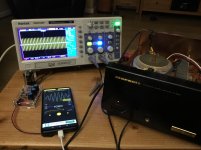
Hopefully I'll be able to start making use of this digital scope that I have (hantek) to also start troubleshooting once I figure out where is safe to put it. I'll keep it from mains voltage but maybe start trying to poke around from the input rca sockets and boards to see what I can observe.
I think I have a small signal generator somewhere I could try to use on the input.
I've a vague feeling the voltage to the amp board was around 35v px2 but will check.
There's a little red relay to on the long board that runs beneath the front panel. In terms of testing power to a relay (where you can't access the legs while everything is in situ) Ill identify the other components that share a connection and test at that point.
Hopefully I'll be able to start making use of this digital scope that I have (hantek) to also start troubleshooting once I figure out where is safe to put it. I'll keep it from mains voltage but maybe start trying to poke around from the input rca sockets and boards to see what I can observe.
I think I have a small signal generator somewhere I could try to use on the input.
You can easily check if the +24V supply for the relays is present by toggling the 'SOURCE DIRECT' switch....I have read of problems with relays on marantz amps, but if that was the case would it prevent any output at all through either the speaker terminals AND the headphone socket?
If you don't hear the 'SOURCE DIRECT' relay engaging/disengaging, you've lost the +24V supply.
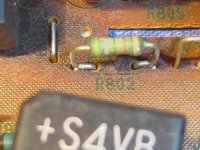
R802 is the prime suspect and Q801 may be loose.
Good Luck!
https://www.diyaudio.com/forums/attachment.php?attachmentid=843903&stc=1&d=1589443541
Attachments
Last edited:
Thanks very much for the suggestion, I will check those components later today once I finish work and spot where they live on the boards.
I did check the relays though just now.
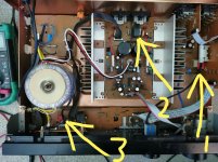
The one on the source control/input board (relay marked 1) is working when I switch the source direct as you suggested.
Neither of the other 2 relays marked are doing anything at any point though, either at power up or down or any other point.
I did check the relays though just now.
The one on the source control/input board (relay marked 1) is working when I switch the source direct as you suggested.
Neither of the other 2 relays marked are doing anything at any point though, either at power up or down or any other point.
Attachments
That suggests R802 & Q801 are functional. It also suggests that there is a more serious issue and the protection circuit is engaged....I did check the relays though just now.
The one on the source control/input board (relay marked 1) is working when I switch the source direct as you suggested.
Neither of the other 2 relays marked are doing anything at any point though, either at power up or down or any other point.

With your trusty meter (or DMM), measure the voltage between the chassis and each centre pin of the large transistors on the heatsink (skip the little transistors).
N.B. ±Voltage polarity is NOT optional and shorting adjacent pins with your meter probes is NOT ALLOWED!
Please post the results.
Also measure the voltage between the chassis and each centre pin of the large white resistors and post the results.
Good Luck!
P.S. Which transistor did you replace?
...There was also a transistor that looked nasty so replaced that too.
Last edited:
OK the test of those is showing that
Centre pin voltage on the rear pair of the large transistors is 43.7v
Centre pin voltage on the front pair of them is - 43.6v
Is that right that the polarity is the opposite way between the front and rear pairs?
This was done with no input signal and no speakers attached. Volume control at 9oclock if that makes any difference.
The other voltage on the mid pin of those resistors is - 10mv on the left one and - 13mv on the right one (facing the front of the amp).
For what it's worth the 3 pin power cable from the psu to the centre of the amp board is supplying 2x 33vac.
Some nice warmth from this amp once its been on a while too. Nothing nasty though and no horrible smells.
The transistor I changed was either the 2sc4883 or 2sa1859 on the amp board. Possibly both. I don't think either had visibly blown but both have a very dark area on the board beneath which suggested to me too much heat possibly from these overheating and failing. Think I'd sent a photo of the board to a mate that repairs quite a lot of electronics and he'd suggested that.
PERFECT!OK the test of those is showing that
Centre pin voltage on the rear pair of the large transistors is 43.7v
Centre pin voltage on the front pair of them is - 43.6v
For future reference, unless otherwise specified, the volume control should always be @ ZERO/minimum during diagnostic testing with no speakers connected. My apologies for neglecting to state this requirement even though it made no difference in this case.This was done with no input signal and no speakers attached. Volume control at 9oclock if that makes any difference.
PERFECT!The other voltage on the mid pin of those resistors is - 10mv on the left one and - 13mv on the right one (facing the front of the amp).
That's great info... Thanks!For what it's worth the 3 pin power cable from the psu to the centre of the amp board is supplying 2x 33vac.
Despite the beating that both Q801 (severe) & Q802 (less severe) take, they are remarkably resilient.The transistor I changed was either the 2sc4883 or 2sa1859 on the amp board. Possibly both.

I performed the following (poorly documented) modification.

Check ALL the cabling between the circuit boards around the headphone relay (number 3 in your supplied picture)

If possible, try connecting headphones to the ¼" Jack and listen for relay activity.
If you hear nothing, you may have to start probing the following;

Good Luck!
That's great thanks. And I'm reasonably sure it was 801 I replaced but might have been both.
Only thing I can find a record of buying at that time was a STF3NK80Z, but not sure what for. I just know though that I defo replaced at least one of that pair you showed in your video.
Tried headphones and there's not so much as a snap crackle or pop through them, or any buzz, hum either when plugging in or otherwise, and not a peep from the corresponding relay during any of this either.
That suggests that the 'protection circuit' has been triggered or has a weird failure (improbable, but not impossible), both the speaker and headphone relays are open-circuit (highly improbable, but not impossible) or that there's something amiss with the 'MUTE function' circuitry or cabling (much higher on the probability scale)....Tried headphones and there's not so much as a snap crackle or pop through them, or any buzz, hum either when plugging in or otherwise, and not a peep from the corresponding relay during any of this either.
Sanity/function check.
Using the remote control make sure that the 'Volume Up/Down' and 'Mute' functions are fully operational - you may not hear any relay clicks due to the current fault, but the 'MUTE' LED should illuminate.
If the above functions are good, set minimum volume and 'MUTE' off.
Measure the voltage between the wire link (in the large white circle) and chassis. Toggle the 'MUTE' function several times (always return to 'MUTE' off).
If there's nothing on the wire link, repeat the process whilst pushing/moving/jiggling the cables in the area around the headphone relay.
If you don't see or hear anything during this process, power-off the amplifier and measure the voltage between the anode of DN03 (small white circle) and chassis.
Power-on the amplifier.
The meter may show random voltage readings, then 0 (hopefully) after the protection circuit delay. This test may be inconclusive or show nothing if the +24V relay supply is missing.

Please post the results.
Good Luck!
Last edited:
Ok, just done those tests thanks.
First thing is that the motorised volume control did function after I reflowed all of the solder joints of the amp board the other night. Today however it has decided not to work again - no idea why, I wiggled all the cables but to no avail, so will have to investigate further again later I guess. Annoying but hopefully not a show stopper right now.
The mute function from the remote works fine in respect of toggling the LED.
There is no audible relay activity however when this occurs.
Voltages -
The wire link shows a solid 24v regardless of whether the mute function is engaged or disengaged.
The anode of the diode you said shows 24v when powered on, and after powering the amp off, this voltage falls off slowly. I watched it drop down to 0.5v which took a couple of minutes maybe but at that point it was dropping so slowly that it would have been absolutely ages to see if it actually ever reached zero, so I hope that's ok for test purposes at least.
Absolutely no audible relay activity through any of this though. Literally through everything I've done so far with the amp, at any point the only time I hear a relay do something is the one on the RCA input board board which switches when source direct is toggled. Neither the headphone relay nor the one on the amp board appear to toggle with anything I tried so far.
Hope that helps!
All this is really making me want to invest in a nice meter than the cheapo one I have.
I learned many years ago about cheap tools being a false economy and have been so much happier/poorer since then after spending on decent tools, and yet still keep using really cheap multimeters. I need to rectify this (no pun intended).
I learned many years ago about cheap tools being a false economy and have been so much happier/poorer since then after spending on decent tools, and yet still keep using really cheap multimeters. I need to rectify this (no pun intended).
That's due to R584 (which I'd overlooked) and is expected. Plugging in headphones should remove the +24V from the wire link....The mute function from the remote works fine in respect of toggling the LED.
There is no audible relay activity however when this occurs.
Voltages -
The wire link shows a solid 24v regardless of whether the mute function is engaged or disengaged.
That suggests the 'improbable' has occurred. It'll be virtually impossible to find a genuine TA7317P. BUMMER!The anode of the diode you said shows 24v when powered on, and after powering the amp off, this voltage falls off slowly. I watched it drop down to 0.5v which took a couple of minutes maybe but at that point it was dropping so slowly that it would have been absolutely ages to see if it actually ever reached zero, so I hope that's ok for test purposes at least.
Further (possibly fruitless) troubleshooting actions in order to explore why the TA7317P has failed (or has been triggered) would be to measure the voltages present on each pin by measuring the voltages on the components directly connected to each pin... there's no way you can get probes directly on each pin without a high risk of causing collateral damage to the amplifier.
An extremely risky and NOT RECOMMENDED course of action would be to bypass the protection circuit (assuming that the TA7317P has failed).
Good Luck!
OK thanks man, I will attempt to measure the voltages on that ic later on today once I'm free.
Seems slightly odd that it would fail one channel first and then the other one afterwards if it was that component, but I suppose it could be that the first failed channel suffered an additional issue first then the protection circuit broke, finishing the job.
Is then an alternative part that might be able to be used instead of that if it does prove to be faulty?
If not, then I guess the choices are to throw the amp away, Or bypass the protection circuit (I'd have to look at how or if I could add something else to do that) and maybe ressurrect it at the risk of destroying speakers if something else fails.?
It's a separate issue - most probably a bad/dirty relay contact....Seems slightly odd that it would fail one channel first and then the other one afterwards if it was that component, but I suppose it could be that the first failed channel suffered an additional issue first then the protection circuit broke, finishing the job.
There are loads of protection circuit boards available on Ebay. You'd have to 'graft one in' to the existing amplifier....Is then an alternative part that might be able to be used instead of that if it does prove to be faulty?
I cannot vouch for their efficacy.
However, there are far superior solutions available and discussed in this forum.
Good luck with your chosen path/solution and heed Harry Callaghan's advice!
ADDENDUM: Discussion on Ebay parts.
More discussion on superior solutions.
Yet more discussion on superior solutions.
Last edited:
Whilst it's possible that the TA7317P has failed (improbable - that only happens in capacitor/semiconductor replacement forums), further troubleshooting actions (whilst powered-off) should include (but not limited to) checking QN03 for Emitter-Collector short and ALL components within the GREEN outlines.
I have included a circuit segment from the PM-44SE circuit diagram as it's much clearer than the PM-66SE circuit diagram (they have identical functionality).

If the above checks prove inconclusive, you'll need a bulb limiter (cheap example follows...).

Good Luck!
I have included a circuit segment from the PM-44SE circuit diagram as it's much clearer than the PM-66SE circuit diagram (they have identical functionality).
If the above checks prove inconclusive, you'll need a bulb limiter (cheap example follows...).
Good Luck!
- Home
- Amplifiers
- Solid State
- Marantz PM66SE signature - repair/troubleshooting