First observation of the evening is that the 24v showing at that wire link remains present when the headphones are plugged in, which sounds like it shouldn’t be the case.
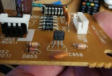
Secondly, yesterday you said to check around the area of the 852 transistor on the little power board P851 just above where the headphone jack is.
That 852 transistor actually has 24v on all 3 legs, and that remains the case even when I plug headphones in. I’m fairly sure that’s not right, it wouldn’t make sense to me, so I’m wonder if possibly that transistor has failed open or something and it’s having a knock on effect down the line?
The power transistor nearby has 5v/1mv/33v across it, which again doesn’t change whether headphones are in or out.
The little diode next to the headphone relay has got 24v both sides of it, phones in/out.
Last edited:
The second sign of something not right that i also spotted is there’s a 4 pin connector joining the control board P501 to the phono input board P451. It’s meant to have -18v which it has got, and +24v but the latter is only showing +17v, which is considerably less.
That said, on the schematic it shows one end of this cable being 24v and the other end being 16v so Ive no idea how that’s meant to work.
Both boards themselves are marked -18 and +24 though so I still think it’s suspicious even if the diagram (sort of) backs up what I can measure.
That said, on the schematic it shows one end of this cable being 24v and the other end being 16v so Ive no idea how that’s meant to work.
Both boards themselves are marked -18 and +24 though so I still think it’s suspicious even if the diagram (sort of) backs up what I can measure.
Excellent observations Sir! 😎First observation of the evening is that the 24v showing at that wire link remains present when the headphones are plugged in, which sounds like it shouldn’t be the case.
I'm surprised, but not unduly concerned with the above. All that would happen is that the speakers would remain on when headphones are inserted.
However, it's always possible (but highly improbable
 ) that I've missed something on the circuit diagram.
As there's no 'load' (under the current fault condition) on Q582, these readings are not surprising (if you enable the 'MUTE' function, the BASE voltage may drop by 0.666VSecondly, yesterday you said to check around the area of the 852 transistor on the little power board P851 just above where the headphone jack is.
That 852 transistor actually has 24v on all 3 legs, and that remains the case even when I plug headphones in.
 ).
). Q851 is a +5V regulator and you've confirmed that it's fully-functional.The power transistor nearby has 5v/1mv/33v across it, which again doesn’t change whether headphones are in or out.

As the relays are currently not energised, that's expected. However, if that diode (DN51) or DN03 are open-circuit, the TA7317P will be destroyed. Explanation.The little diode next to the headphone relay has got 24v both sides of it, phones in/out.
Another great observation...The second sign of something not right that i also spotted is there’s a 4 pin connector joining the control board P501 to the phono input board P451. It’s meant to have -18v which it has got, and +24v but the latter is only showing +17v, which is considerably less.
The reason it's no longer @ +24V is because the supply passes through RW01 (270R/2W) and drops some volts (the adjacent pin 'DIR' should be @ +24V when the 'SOURCE DIRECT' function is enabled).
+17V is a bit low - there's an 18V Zener on the RIAA board that won't be 'zenering' properly, but it's not a show stopper.
The reason the headphone and speaker relays are not engaging is that pin 6 on the TA7317P is not going LOW.
The reason why pin 6 is not going LOW has yet to be determined.
If you're confident that you can get probes on the TA7317P pins (or attached components) without causing collateral damage whilst powered up, go for it and post the results.
Nice work... And Good Luck!
Last edited:
OK now I think I'm getting near part of the problem at least.
I removed the front panel and removed the 4 attached boards and inspected them.
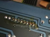
Instantly spot that the connection of the cable from P851 power board to P501 control board is proper nasty looking, and appears to have been messed with before as it looks like a big patch of flux or something around it. These connections are all super close to the headphone relay which is not doing anything.
Now something odd about this setup is where that cable begins on the little power board, it has a track feeding each core of the cable, but where it joins this big board only 2 cores actually appear to go to anything!
Seems like a single layer pcb so I'm assuming the other cores have no purpose, maybe for a different model where that board does more stuff perhaps. I'll check the diagram to be sure.
Anyway, despite looking bad they seem to have good continuity, but I don't think it's a coincidence that this looks bad and appears to have been resoldered, while there's an issue with the nearby relay, and the transistor on the board feeding this appears to have shorted open.
So I guess I'll have to order one or a few of those transistors to replace it and see if it helps, unless there's some sort of temporary bodge just to see what would happen if it was working briefly?
I removed the front panel and removed the 4 attached boards and inspected them.
Instantly spot that the connection of the cable from P851 power board to P501 control board is proper nasty looking, and appears to have been messed with before as it looks like a big patch of flux or something around it. These connections are all super close to the headphone relay which is not doing anything.
Now something odd about this setup is where that cable begins on the little power board, it has a track feeding each core of the cable, but where it joins this big board only 2 cores actually appear to go to anything!
Seems like a single layer pcb so I'm assuming the other cores have no purpose, maybe for a different model where that board does more stuff perhaps. I'll check the diagram to be sure.
Anyway, despite looking bad they seem to have good continuity, but I don't think it's a coincidence that this looks bad and appears to have been resoldered, while there's an issue with the nearby relay, and the transistor on the board feeding this appears to have shorted open.
So I guess I'll have to order one or a few of those transistors to replace it and see if it helps, unless there's some sort of temporary bodge just to see what would happen if it was working briefly?
Attachments
Sorry just saw your post above after sending that one!
Thanks for all the explanations on those points, I must admit I was quite baffled by the apparent missing voltage on that cable!
I think I can get to the pins on that ic but I have the whole thing in bits just now so would need to reassemble it all first, but before I do I'll resolder this cable, and potentially try to carefully prise off the cover of the relay to see if it is free inside, or possibly look up the connections for it and apply a test voltage to see if it functions when powered directly at least, then I know the relay itself isn't faulty before the hassle of reassembling everything.
Not sure if there's anything else I can check before I reassemble it.
Also that motor control thing working a day or so back then not working now is bugging me.
I checked the voltage to that and it seems to be only something like 1-1.5v from memory. Doesn't seem much.
I checked the remote emitter is functioning with the volume buttons too by pointing it at my phone camera and I can see it happily flickering away so it's not the remote.
Last edited:
Just tried to energise that relay by the headphone socket while I gave this apart. Found the right pins (separate from the other pins). Data sheet says it should open from about 16 or 17 volts but no joy. I think it's knackered as it just tries to draw a load of current. Will see if I can open it and move the innards tentatively.
OK can confirm that headphone relay 100% is faulty! Repeated the same energise test on one of the other identical ones and it worked absolutely fine.
So I'm suspecting possibly when that's died it's overloading something else and caused a fault elsewhere.
Will operate on it to see if it can be rescued at all, but either way will then reassemble and then rest that suspect ic.
Last edited:
Great observation... And only 2 x conductors (pins 2 & 7) are used in this amplifier....Now something odd about this setup is where that cable begins on the little power board, it has a track feeding each core of the cable, but where it joins this big board only 2 cores actually appear to go to anything!
And that PCB is a bugger to remove.
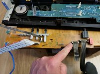
The resistor to the left of your finger in the 3rd picture is where the +24V loses some volts and becomes +17V. Check that it's still 270R.
"Shorted open" is an oxymoron....and the transistor on the board feeding this appears to have shorted open.

Be aware that Q852 has several components across it which may cause erroneous readings on your DMM. If in doubt, remove it and test. However, a short-circuit is always close to zero Ohms (0R).
A semiconductor package can 'masquerade' itself as follows;
1 - Semiconductor - desirable.
2 - Wire (short-circuit) - undesirable.
3 - Air (open-circuit) - undesirable.
If you're NOT 'risk averse' and prepared to see/smell magic smoke and potentially do lots of damage, you could solder a 'flying lead' onto the Anode of DN51 (ICOUT)....Not sure if there's anything else I can check before I reassemble it.
With power applied, grounding the other end of the 'flying lead' would energise the headphone and speaker relays.
It also means that the 'Protection' circuit is bypassed. 😱
**** DO NOT CONNECT SPEAKERS TO THE SPEAKER TERMINALS ****
It may also cause 'magic smoke' to be released if there are other undiagnosed issues.
Good Luck!
Good point about the oxymoron, it's either shorted or open circuit if it fails, not sure where that came from!
No I'm not really risk averse, I'm usually fairly happy to try things that might be a bit reckless, sometime they end with weeping and grinding of teeth and other times not.
Might try that potentially then but first if anything I'll need to reassemble it all and test the pins on that ic near the speaker relay.
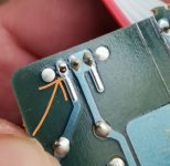
The headphone relay is trashed though. I opened it and its very hard to physically see where the issue is with it in situ, but the coil on it is shorted/has continuity, whereas the coil on one of its brethren is 1k ohms across and does not have continuity.
Since its clearly wrecked, for now I'm tempted to sever one of the connections to the coil of the relay, since anything trying to energise it is potentially going to cause a problem as its supplying power directly to a shorted coil.
Also, found the motor control fault from the look on things. Loose pin on the power feed for it.
No I'm not really risk averse, I'm usually fairly happy to try things that might be a bit reckless, sometime they end with weeping and grinding of teeth and other times not.
Might try that potentially then but first if anything I'll need to reassemble it all and test the pins on that ic near the speaker relay.
The headphone relay is trashed though. I opened it and its very hard to physically see where the issue is with it in situ, but the coil on it is shorted/has continuity, whereas the coil on one of its brethren is 1k ohms across and does not have continuity.
Since its clearly wrecked, for now I'm tempted to sever one of the connections to the coil of the relay, since anything trying to energise it is potentially going to cause a problem as its supplying power directly to a shorted coil.
Also, found the motor control fault from the look on things. Loose pin on the power feed for it.
Attachments
Last edited:
That's an excellent (and worrying) discovery!...Also, found the motor control fault from the look on things. Loose pin on the power feed for it.
Good Luck!
Well now its all reassembled I was ready to test that ic but there's a new issue it seems.
The motor control is great now, but the amp won't stay powered on.
Now I could swear prior to now that the power switch was a latching one, not momentary and that the power button stayed further in or out depending on status.
But since reassembling the amp the switch reverts to the same position after you let go, and a few seconds after doing so the power led goes off and its game over.
Can't imagine how this has become a thing suddenly but makes it very tricky to test stuff now.
Hi. I'm also trying to repair my PM-66SE which i own from new. Suddenly right channel started to fail. Now it failed completely. I took device apart, checked points mentioned in previous points. Bias measurement on R756 shows 0mV. Also if I measure middle point of Q762 this shows 0V, all other output transistors show 41,6V towards case. Any suggestions? Has the Q762 died? I really kindly ask for some help.
I have just repaired my PM-66SE the .47ohm fusible resistor R802 had fail (replaced with 1/2W) and I also replace the relay, removed the glue from around the large caps and two of the resistors under the glue. I have looked on line for a User Guide/Manual but can't find one, however, the PM-66SE is working and sound great but I'm not sure how the mute switch should operate. With the Tape 1 & 2 led's off and the Mute switch in, I have a direct source and no balance control, with the mute button out I have the balance control working but the LED above the source button does not light in either position is this correct?
You should search for service manual (with schematics).I have looked on line for a User Guide/Manual but can't find one,
I have the service manual with schematic which I used to repair the pm-66SE, but as I stated above the mute light operation is not covered in the service manual and that's why I asked re its operation, as I can't find a USER GUIDE online........ not the service manual!!!!
Internet pictures do not show any mute switch on front panel (a led is there so it is probably operated via the remote control) - can you post a photo of your amplifier?I'm not sure how the mute switch should operate. With the Tape 1 & 2 led's off and the Mute switch in
Thanks, I think that could be the answer, I don't have the remote so I can't test just yet, I will have another look to see if I can find the user guide to see if you are correct. Purchased both off Facebook Marketplace with no output CD was just a dry joint on on the Audio output socket ground and as I said previously the amplifier had a blown R802 plus a changed the relay and two other resistor covered by the brown glue.

It seems that also the inputs are controlled by the microcontroller chip, perhaps it has remained in some undetermined state and needs a "push" from the remote control.
Besides original RC units you can probably find shops in the net who can program universal units per necessary model.
Besides original RC units you can probably find shops in the net who can program universal units per necessary model.
I'm not so sure that in this amp, the RC controls the inputs as the selector switch is a mechanical device. Also, the block diagram in the service manual shows that the UC only controls the speaker relay (for mute) and the motorized volume control.
The button on the front panel below the mute LED is the source direct switch, not the mute switch. In the SE-models, tone controls were omitted. In these models, the source direct bypasses the balance control and the tape in- and outputs. In the normal models, it would also bypass the tone controls.


The button on the front panel below the mute LED is the source direct switch, not the mute switch. In the SE-models, tone controls were omitted. In these models, the source direct bypasses the balance control and the tape in- and outputs. In the normal models, it would also bypass the tone controls.
Last edited:
You may be correct...I'm not so sure that in this amp, the RC controls the inputs as the seletcor switch is a mechanical device.
But I fail to find a mechanical mute switch in the schematics.
- Home
- Amplifiers
- Solid State
- Marantz PM66SE signature - repair/troubleshooting