For Sale Jeff Bagby Continuum II Speaker Kit (Pair)

Selling the kit components for a pair of Jeff Bagby's Continuum II speakers. I bought the kit from Meniscus a few years ago, assembled the kits in cabinets I built, and used them in a second system for two years. They haven't been overdriven, and everything is in great shape...should be as good as new. The drivers are Aurum Cantus AC130-F1 and Morel CAT308. Includes what you see in the pictures - drivers, wired crossovers, wiring terminated with quick connects, foam lining for cabinet walls, instructions with schematic and cabinet plans, binding posts, and screws for mounting drivers and crossovers. The kit retailed for about $400 when I bought it. With the closing of Meniscus, I don't think either the kit or the plans for the Continuum II are currently available.

Note that cabinets are NOT included.

Asking $280, including shipping to continental USA.

Co1.jpgCo2.jpgCo3.jpgCo4.jpgCo5.jpg

I made a USB highspeed ISOLATOR

I made an isolator board using Analog Device's ADUM4166 chip.


Recently, TI and Analog device both produce isolator chips that support 480Mbps High speed.


TI's chip ISOUSB211 is a redriver, while Analog device's isolator chip ADUM4166 / 4165 is also retimer.


Analog device's isolator is a 24Mhz clock with a RETIMER function that can reset timing jitter.


In effect, the noise of the PC at the front is essentially blocked, and the clock jitter can be resolved by this reclocking isolator.


Considering that there is almost no transmission error although the USB data signal is poor.


It seems to be a fundamental solution to PCfi noise.


I made the cad using EASYEDA .
and orderd from JLCPCB.COM/KOR


in EASYEDA You can check the inventory of parts such as terminals and devices from the manufacturing process.


All parts except the tantalum polymer cap and USB A type terminal were already mounted on the JLCPCB, so it took very little time to make them.

In the case of the optional tantalum polymer, the internal resistance is only 5 milliohms.


I believe it has a lower internal resistance and total impedance than supercap or lithium polymer battery.


The board is an impedance-matched 4-layer board...


I also put an ESD protection element on the input.


The board is designed to minimize the length of stubs that can be created in the USB signal line noise and abnormal transmission.

The clock used is a 2520 size TCXO with a stability level of 0.5ppm. The clock is powered individually by LDO.


The external power supply of 5 volts can be used as a cell phone charger or GAN adapter.


The type C terminal is negated by a pull down resistor on the CC pin.


It can draw up to 5V 3A from a PD charger, so it can be used in professional equipment such as audio interfaces that consume a lot of power.


However, power noise from the charger can enter the DAC.

so I covered it with a common-mode noise filter and tantalum polymer with an extremely low ESR of 5 milliohms.

so that you don't have to worry about the power supply such as battery or linear power as much as possible.


As for the casing, I have a 6cm long aluminum chassis so it fits right in there, I think I'll just have to mill the front and back plates.


I'm testing it between the tinkerboard installed volumio and the AD1865 DAC.


I'm very happy that it worked from the first test^^.


music comes out well.


The effect on sound is easily noticible. I noticed more low bass appeard at first. and more refined mid and highs.

1.28 Billion US Dollars - to play or not to play. That is the question

The Mega Millions jackpot has risen to 1.28 Billion (!) dollars. The drawing is tonight at 11pm EST (UTC-5 I think).

Should one play or not? If you don't purchase at least 1 ticket (plus the multiplier) you have zero chance to win any of the prizes. But the odds of winning are astronomically against any individual actually winning anything at all.

So, I ask, do you feel lucky? Do ya punk? (Clint Eastwood reference there)

PP 2E22 amp rebirth

I recently mentioned the history of this amp in another thread.
Built entirely (including PT, starter and OPT) by a guy from my area (career soldier) who has now decided to retire from the world.
This amp partially burned 3 years ago, the power transformer having decided to transform into an independent heating system, it tried to get calories from anything that was flammable next to it (including the table on which it rested).
I requested information by email several times from this person to rebuild the amp in good conditions but have not had a response since he left the world.
I come here to ask for information about the schematic, to know if it is stable and/or if there are improvements/modifications to be made.
It was one of my favorite amps, I only found it a little short in the bass (for my taste, I never measured it)
Out of respect for this person, I have erased his name from the schematic, some French people will recognize his work, I do not want any controversy (there has been some in the past on his PP 845), please do not do it again.
I haven't bought a power transformer yet, I left this amp in quarantine in an isolated place in the house because it smells really bad.
It's a long-term project, but it's a start.
PP2E22 evo jpg.jpg

Before the incident
1711612238931.png

1711612261499.png


I have another amp made by him (copy of a pair of Leak TL25+ in a common chassis and common power supply) which has been performing well for years.

6146B datasheet puzzle

I wanted to refresh my memory and looked up the 6146B.
Now, some decades ago i used the quite similar QE05/40 in triode.
To my suprice :
RCA 6146B Rg1 fixed bias 30k
Philips QE05/40 Rg1 fixed bias 100k
Now, nobody wants tube run away, it could be that RCA
choosed a bigger safety factor or whatever, doesn matter.

But, what earlier went unnoticed by me, and really puzzles me,
what could be the reason for: ...only FIXED bias is recommended?

Downsides to port noise

Other than the noise itself, is there a downside to port noise? Does it "choke" anything or cause anomalies in the enclosure response? I have a small (about 0.6cf) PVC pipe enclosure that I want to put some isobaric 8" drivers into, but it looks like I start getting port noise if I go below 2.5" diameter for the port. Problem is, the port length (don't have all the math in front of me now) starts getting too long to be practical, and will be tough to package.

If I drop to a 2" port, it predicts audible port noise, but it will let me do a more "normal" length port of 10" inches.

Since this will be installed behind a plywood panel in a van, and the driver will be 10' from my ears, I'm not worried about actual audible port noise, but I don't want to sabotage the sound quality if port noise does other bad things. Make sense?

6J1 / 5654W Hybrid

A while back I had been playing with the el-cheapo 6J1 china preamp.
Even after fixing up some of the many flaws, I was never really satisfied with how it sounded.

After some reading around I came across this build by Ratti3: 6J1\EF95 Hybrid Tube Preamp.
I had a box of NOS GE 5654W's that needed a suitable home, so down the rabbit hole I went.

Adapting the scheme from Ratti3's creation, I came up with the following, running off a simple 12v Wall-Wart:

Scheme.PNG


1711778007834.png


The HV power supply comes from this cheap boost module:

HV Module.jpg


This HV supply is filtered sufficiently to not impose much noise into the system.

The main amplification is done by a single 5532 which although is sufficient, a future iteration could benefit by having either another in parallel or a simple BJT stage.

The board design:

Board#d.PNG


PCB (Don't have any pics of it populated to hand):

20230829_234809_resized.jpg


And in a finished case:

20240118_150847_resized.jpg


Measurements:

Table.PNG


As can be seen, the THD is at 0.8%, but this amp has heaps of H2 making it lovely and warm:

THD.PNG


All in all, a simple headphone amp with that nice warm 'tube' sound.

Thanks to @Ratti3 for posting his design that I used as a launch point.

Accuphase P600

Hello,

I bought a defective Accuphase P600.
Unfortunately one side of the power amplifier is broken. All 2SA1170 and 2SC2774 are defective. Does anyone have a tip where I can get these as not fake? Or can I install a replacement, which shouldn't actually be done with a device like this.

Does anyone perhaps have a circuit diagram of the device?

Kind regards, Mario

WHAMMY headphones amp

Hi,

Got this newly, fully build whammy headphones amp laying around. Also got pcb’s or if you want, compleet kits to build.

Looking for 200 euro plus shipping from the Netherlands for the fully build.70178f31-439b-4022-bcb6-6d5e17e816c9.jpeg

Attachments

  • 5ae0580d-f683-41be-84a2-12fa290ffe03.jpeg
    5ae0580d-f683-41be-84a2-12fa290ffe03.jpeg
    159.3 KB · Views: 89
  • ca499c32-1b2d-4457-84df-0ec3f3fbd021.jpeg
    ca499c32-1b2d-4457-84df-0ec3f3fbd021.jpeg
    218.6 KB · Views: 92
  • 6cb54717-97b8-4307-a6f4-8734a3e1517b.jpeg
    6cb54717-97b8-4307-a6f4-8734a3e1517b.jpeg
    193.8 KB · Views: 110
  • 3077aa17-12e6-4171-bf90-d0ed2f887c31.jpeg
    3077aa17-12e6-4171-bf90-d0ed2f887c31.jpeg
    408.9 KB · Views: 98
  • e73412a2-dcbe-4df1-a0d1-b9428a22d806.jpeg
    e73412a2-dcbe-4df1-a0d1-b9428a22d806.jpeg
    240.1 KB · Views: 105
  • 3f67518d-02ca-4e9a-a5ce-69d0ec0caa52.jpeg
    3f67518d-02ca-4e9a-a5ce-69d0ec0caa52.jpeg
    158.9 KB · Views: 101

  • Locked
I can’t start Spotify on my PC

Greetings, friends. I hope you're doing well. Best wishes to you all. Hi! This is my very first visit to this website. I'm not sure if this is the correct location. I can't launch Spotify on my PC because of some unexplained issues; instead, I get an "Oops! Something went wrong Spotify" message. This is a problem that neither I nor my IT support can solve. Your suggestions would be quite helpful.

Is an Omron MY4-02-DC24 relay a drop in replacement for a Takamisawa MAT4B 212R 24V relay?

It is a Sanyo Plus P55 power amp which has the Takamisawa relays. I have seen a suggestion that an Omron MY4-02-DC24 can replace the original Takamisawa MAT4B-212R 24V but before possibly spending money on two relays that may not be compatible, I thought I'd look for confirmation here.

If I order replacement Omron Relays with pins, not lugs, can anyone confirm the pinout and pin spacing will be correct?

There is are small traces of what looks to be rust inside the original relay so I believe replacement would be logical.

I cannot comprehend what I see on an Omron datasheet to compare with the diagram printed on the Takamisawa housing.


IMG_5300.JPG


IMG_5302.JPG

Repair, Restoration Recommendations for my Quad ESL 57s

OK, I think it's finally time to get my 57s worked on. After 40 years of ownership, one no longer powers up and there's some buzzing in one of the panels. I run them on a pair of Dynaco kit monos and a Spectral preamp from Richard Fryer decades ago. With a sub, I've loved these Quads.

I do plan on having a professional do the refurbishment, but am wondering what updates or modifications would good to do while we're at it.

Rewinding a 330VA Toroidal transformer

I want to build a low noise linear bench PSU with an electrostatic screen. I have a Cotswold Electronics 240V, 330VA toroidal with a burnt out primary which I intend to rewind; I know it's not economically sensible but a) nobody is paying me for my time, b) screened transformers are hard to find, never mind at a reasonable price and c) I fancy the challenge.

I have removed the 880 turn, .8mm dia. primary winding which was on top of the secondary. At 127m the primary would have been 4.2ohms which is reasonable for a 330VA 240V transformer. Assuming there are 5% additional primary windings to compensate for the voltage drop due to winding resistances (regulation) that gives 3.5turns/V.

The core dimensions are approximately (I haven't removed the secondary yet) 118mm outer dia., 62mm inner x 35mm depth giving a core area 9.8cm^2. At 3.5 turns/volt that implies a flux density of 1.3 Tesla. That seems a bit low by current standards but this is a late 1970's transformer. It weighs 2.8kg

The 2x35V secondary are 1.85mm dia. and measure .206 ohms each giving 2.7% voltage drop at max load, compared to 2.4% for the primary.

So the questions:

I intend to use .95 or 1mm dia wire for the primary to give me headroom to increase the output power if needed (>= 358VA for 2 x 100W outputs). There is sufficient winding space to accomodate this although it will make the winding a bit more difficult. The wire comes in 2 x 500g reels so it's tempting to do 1 x 115V + 1 x 115/125V windings. But I haven't managed to find out how these are typically wound on a toroid - one on top of the other minimises the layer to layer voltage stress (5 layers in total for 240V) but the two windings will have differing resistances. I guess the difference would be small enough to ignore. Bifilar winding would mean an unacceptable (?) 115V wire to wire stress all the way through the primary. Otherwise I guess the two windings would each have to be wound back and forth over 180 degrees of the core with insulation between the two windings where they meet. This would be awkward.

1) Primary windows on top of each other?

2) Is it worth considering any interlayer insulation in the primary (I have 50micron kapton tape)? I have never seen this done but I've seen it suggested to minimise the stress on the magnet wire insulation, especially given the increased risk of mechanical damage when hand winding.

3) What rating thermal fuse(s) should I use? I have 2 and 3 amp fuses to hand which should be ample - except that I cannot find any surge ratings for thermal fuses. Chances are that I will need inrush current limiting anyway but it would be a shame to install thermal fuse(s) that could be at risk of failing from the stress of a few hundred power-on surge events.

4) Is there any disadvantage to using 212C rated grade 2 polyester magnet wire compared to 155C enamelled wire? There isn't any price difference.

5) Commercial transformers typically use 180C rated wire and 130C insulation - but why use PVC insulation sleeve for the leadout wires only rated at 105C? The cost saving on the latter must be negligable but it reduces the overall rating to 105C - which seems odd given that 130C thermal fuses are used (Vigortronix).

6) I have an old Farnell XA35-2T supply (dual 35V x 2A) which hums loudly under load. The toroidal is probably around 400VA. It's quiet at no load so I assume the hum comes from loose windings rather than the core. So how important is it to keep the windings tight to prevent this? Typical toroids that I have don't have impregnated windings so I guess they rely on the insulation tape and /or the mechanical rigidity of thick secondary windings in the case of higher power transformers?

Apologies for so many questions; thanks for any useful insights you can provide.

Connections of RCA Ground with separate mono blocks in same chassis

IMG_20240319_220323.jpg
Masters - please suggest where to connect RCA ground while having two separate power amplifier blocks, and how to connect chassis ground with two power grounds available, as if both grounds are connected with chassis humming started due to looping created same is with RCA ground connection with potentiometer ground shorting. Please suggest me for proper solution, thanks in advance

Noise sensitivity of different measurement algorithms - graphs

A topic comming up at a different discussion about driver measurements. So I sacrificed my lunch break and did some measurements to show you.

In short - it's always important to know your Signal to Noise range, especially when measureing THD. Do I get results or am I looking at noise is one of the main questions in acoustic measurements when you get deeper into details.
A quick and simple way to check is to unplug the speaker and run a measurement - you will measure the actual noise inflicting your measurement.

There is the noise behaviour of the measurement microphone, surrounding noise but also the analysis methode! And the differences can be huge! Let me show you here.
I measured the fan of my APX515 system in 5cm distance - what a great noise source 🤓

Stepped frequency level sweep. An old but standard measurement signal and analysis. 31 dedicated sine frequencies and you measure the level.
AP Fan Noise Stepped Sweep.png

So you measure the broadband noise of the fan at every frequency - pretty bad.

When you do a bandpass stepped sweep the analyser sets a narrow bandpass arround the measurement frequency to eliminate noise of different frequencies. Helps.
AP Fan Noise Bandpass Sweep 3x.PNG

There is quite some fluctuation of the signal - it's noise ... But we see the fan produces mainly low frequency noise, you get a good S/N range at high frequencies!

Now a more modern signal - continuous sweep. It's the analysis with FFTs similar to what you use with MLSS and it's implemented very good here (not every software is the same accurate!)
AP Fan Noise Continuous Sweep 350ms raw.png

This is the reason I use 1/24th smoothing with these measurements - the "hair" doesn't give information for this measurement.

AP Fan Noise Continuous Sweep 350ms 1-24.png

As we have WAY more resolution we see spikes in the response. But we lack resolution at low frequencies - and have a huge spread at 20Hz. Even the stepped level sweep gives more stable results here.

Increasing resolution and sweep time to 2s gives this graph:
AP Fan Noise Continuous Sweep 2s 1-24.png

Now we clearly see our spikes - typical for fan noise. And we have enough information at low frequencies to get a more stable result. This was not the behaviour of the noise source before - it's a problem of the too short sequence and FFT calculation! And still at 20Hz we get more derivation as we want, from 30Hz upwards everything is perfect.


When you use small membrane (1/4") or cheap measurement microphones you get A LOT of noise at low frequencies and it will influence your results and dynamic range of your measurement significant. Choose the right measurement methode and check it!

I hope this gives more light to the toppic of noise sensitivity with acoustic measurements and different measurement algorithms as it brings new questions 🤓

For Sale Used pair Lowther DX3 Speakers

For Sale used a pair of Lowther DX3 speakers with the older straight side wizard ,new foam surroundings,new Voice coil suspension,Original cones

Price for the pair $800.00 USD (lowered price $675.00USD )plus shipping, the lower 48 states only. Please PM me if you are interested

Sold

Attachments

  • A5785105-CEED-4D08-8B8B-DDAB3EDAF360.jpeg
    A5785105-CEED-4D08-8B8B-DDAB3EDAF360.jpeg
    506.3 KB · Views: 439
  • CE1A9DE4-7DF8-4964-BD47-BB1FFC262B54.jpeg
    CE1A9DE4-7DF8-4964-BD47-BB1FFC262B54.jpeg
    581.8 KB · Views: 392
  • BE094F4E-DFA2-466B-B651-4A3E4ECBB843.jpeg
    BE094F4E-DFA2-466B-B651-4A3E4ECBB843.jpeg
    400.2 KB · Views: 314
  • 9397DC18-EC14-4947-A0C3-FB2CB9BE6DFC.jpeg
    9397DC18-EC14-4947-A0C3-FB2CB9BE6DFC.jpeg
    424.9 KB · Views: 402
  • 8E0EDCB6-BFBD-4575-8414-C8D27B3DB86F.jpeg
    8E0EDCB6-BFBD-4575-8414-C8D27B3DB86F.jpeg
    408.7 KB · Views: 312
  • Like
Reactions: jideta

Crossfire BMF 600.4 frequency response

Good day folks,
I got a BMF600.4 in, unit appears to be in original condition. It came in reportdly becoming distorted.

Powers up and verified the unit passes a clean 100hz sine wave on all four channels, however at 10khz, only the front right channel passes a clean sine wave, the other three channels pass a somewhat sawtooth/triangle wave.

When I go lower with the freq all four channels pass clean sine waves. I have clean sine waves leaving the pre/xo section entering the differential pairs.

Anyone ever came across a similar problem as this?

Attachments

  • IMG_6734.jpeg
    IMG_6734.jpeg
    488.2 KB · Views: 67
  • IMG_6733.jpeg
    IMG_6733.jpeg
    461.9 KB · Views: 67
  • IMG_6656.jpeg
    IMG_6656.jpeg
    664.1 KB · Views: 81
  • IMG_6668.jpeg
    IMG_6668.jpeg
    510.4 KB · Views: 68

A parallel BUF634A power amplifier

Hello diyAudio forum,

Currently, I'm using a homebuilt opa1642 + buf634a headphone amp. And i'm happy with it.

So, I have an idea to build a speaker amp with multiple buf634a. This is a schematic for the amp.
제목 없음.png


The amp has 3 stages to boost the power
1. input buffer with a dual opamp, opa1642
2. signal amplifying using the mbl6010d preamp circuit (dc blocking without a capacitor...), two opa1611.
3. each channel has 5 buf634a to increase the current (the opa1611 in the schematic is the socket for the buf634a)

Any comment, or recommedation will be welcomed!

Thanks in adavance.

*Thousands Sold*, Great Reviews... Received Fake AD797 Like LM741. Did You Buy These?

Seeing thousands sold and good feedback I broke one of my own rules and bought "AD797" on Ebay...

Literally thousands have sold (see attached first photo) including over 2,500 in just the five packs.

After extensively searching the feedback containing "AD797" I gave it a try. One feedback even reads "confirmed AD797 device type". What did I get? The branding looks like AD797...


Well the AD797 quiescent current is 8.2mA. I measured 1mA like an LM741... The AD797 input offset voltage spec is 80uV max. I measured 0.3V, 0.8V and 0.9V like LM741...

What about pin 8 which is the distortion cancellation and compensation pin on the AD797? On the ones I received pin 8 is no connect. No diode junction of any kind and completely open circuit. Real AD797 has a connection on pin 8. LM741 is no connect on pin 8.

I probed the offset null circuitry from Pin 1 to 4 and Pin 4 to 5 and it looks like... ...an LM741 with 1kOhm resistors. (See attached images which include an LM741 schematic.)


Since thousands have been sold and given five star reviews... ...I wonder... ...did any other DIYAUDIO forum members buy any? If you did can you please probe yours and post the measurements for simple fake detection? (Such as quiescent current, offset voltage, offset null circuit resistor values. Is pin 8 open circuit?) Do you unknowingly have LM741 in your pre-amp or DAC I/V stage? 😱

Am I the only one who seems to have received LM741 that are marked AD797? (I doubt it.) Did thousands of people really get LM741 marked like AD797 and then leave five star reviews?!? I bought from "Adeleparts2010".

Attachments

  • Thousands Sold.png
    Thousands Sold.png
    847.2 KB · Views: 1,064
  • Fake AD797 Fail Input Offset Voltage Test.png
    Fake AD797 Fail Input Offset Voltage Test.png
    59.4 KB · Views: 1,080
  • Fake AD797 Fail Quiescent Current Test.png
    Fake AD797 Fail Quiescent Current Test.png
    52.2 KB · Views: 1,003
  • Pin 8 Distortion Neutralization.png
    Pin 8 Distortion Neutralization.png
    44.1 KB · Views: 973
  • Fake AD797 Missing Pin 8 Distortion Cancellation Connection.png
    Fake AD797 Missing Pin 8 Distortion Cancellation Connection.png
    52.3 KB · Views: 995
  • LM741 as Fake AD797.png
    LM741 as Fake AD797.png
    102.4 KB · Views: 403

For Sale Ian Canada full streaming system including upgraded SC-Pure clocks, HDMI pro, Q7, Transport PI pro etc

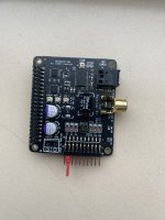
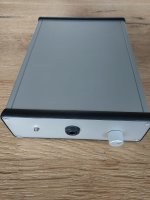
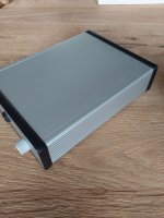
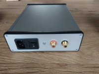
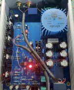
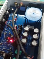
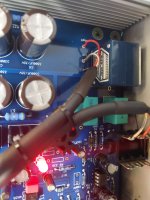
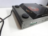
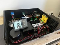
Up for sale is my Ian Canada streamer components including the PI4 Modb

Selling everything together as a set - at this stage
i'm not willing to break these up sorry.

This is by far the best digital transport i have heard by
a long margin. Reason for sale is that i've just purchased
a garrard 301 turntable and investing more in the analog side.

I've included the prices paid for each component below $1465 USD value.
Wanting $950 USD (Paypal only - buyer to pay fee) price includes shipping EMS post with tracking.
These parts are practically brand new and some are unused grab a bargin 🙂


All parts were purchased direct from Ian in Nov/Dec 2023.

The Ifi Ipower X has an Au mains plug and will require a plug
adaptor for USA or UK use (its multivoltage so just req the plug adapter)
These can be purchased from Amazon for approx 18 USD (let me know if you need a link)

The FIFO Q7 also comes with the regular clocks however i swapped
them out for the upgraded Pure clocks after listening to them
for a day or so.

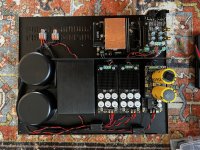
I will disassemble the components then put into the anti static bags
they shipped in from Ian. SCPure clocks will be removed and shipped
in their offical boxes and will re-install the default FIFIQ7 clocks.

The lifePO4 batteries are not supplied (for PurePI as they are not allowed to be shipped
internationally).


** installed on the PI is a licensed Gentooplayer install. I will
supply the license key to the new owner if required, or install
the software of your choosing **


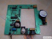
TransportPiAES $139.00
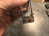
UcConditionerMkII 5V $69.00 (unused) (Needs ultracaps board only)
MonitorPi OLED audio display/analyzer $49.00
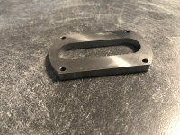
Acrylic protection cover of FifoPi stack (Clear) $8.90
Maxwell Ultracapcitors x2 purchased from mouser $50 usd
(part no: BCAP0325 P270 S19)
SC-Pure Clock 45.1584MHz $179.00
SC-Pure Clock 49.1520MHz $179.00
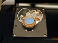
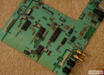
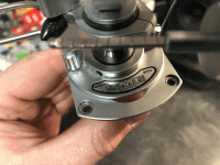
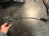
FifoPi Q7 flagship 768KHz I2S/DSD/DoP FIFO with isolator,three stages re-clocker and dual XO $189.00
HdmiPi Pro flagship HDMI transport interface $125.00
UcConditionerMkII 3.3V $69.00 (Maxwell ultracaps soldered on)
StationPi Pro II (fully finished) $76.00
PurePi II 5V + 3.3V ultracapacitor/LifePO4 battery power supply combo $97.00
Raspberry Pi 4 Model B 8GB LPDDR4 Quad Core Cortex-A72 64-bit SoC 1.5GHz... with Samsung Pro PLUS 512GB Micro SDXC $100
AEON AH020 Micro HDMI to HDMI Adaptor - 17cm
Ifi IpowerX 5v/3a (upgraded low noise PSU for Pi) $100
additional spare standoffs and screws
Hookup wire is Neotech Solid Copper Wire (Red) approx $35usd
i purchased 2m and 1m is included uncut.


IMG_2488.JPG
IMG_2489.JPG
IMG_2490.JPG
IMG_2491.JPG
IMG_2492.JPG
IMG_2494.JPG
IMG_2501.JPG
IMG_2504.JPG

Transformer Chassis Seat Antek 300/400

After giving away over 40 of these kits I've got to now at least charge my cost for a kit, which is a little over $5. If you'd like a kit, or two, just PM.

The pics below are old what I have now are different color prints than the blue and white (rainbow colors in TPU material).

The "kit" I'll send includes the "squishy" TPU (thermal polyurethane) seat, a rubber guarded stainless steel pipe strap, and associated hardware (bolts, washers, nuts) to mount your transformer vertically over a "lip up" (or lip down) perforated chassis bottom plate. (it's a complete kit to securely mount the transformer physically to the bottom plate). The 400VA transformer requires 12mm spacers which I'll also include if you note that's what you'll be using it for.
-------------------------------------‐‐--------------------------------------------

20240324_201503.jpg


Hit me up via PM if you need help getting the design printed. I've posted the files for anyone to use with no stipulations. Use as you see fit. If you want to print yourself I'm happy to share slicer suggestions to ensure a good print.

https://www.diyaudio.com/community/...ing-of-antek-300-400va-3d-print-files.410476/

Below is a link to what it looks like installed in the 4U chassis. An Antek 300VA and 400VA both have been confirmed to fit and are very secure (I can lift the entire chassis up by the donut with no slip/slide, so it's solid). I can tweak the design if folks want to use it for a 500VA, but I have not confirmed the stainless steel pipe strap fits over it. At the bare minimum, you may need some extra washers and longer bolts to get a 500VA Antek to fit snug and secure. Height wise, a 500VA transformer will fit just fine in a 4U chassis.

https://www.diyaudio.com/community/threads/f5m-kit.408290/post-7627904
20240316_120521.jpg


You can get an accurate shipping quote at PirateShip.com and I've found they have better pricing than going to UPS or USPS websites.

Package will be a 6x9 padded envelope weighing under 6oz and will be shipped from 98188. [Use this info for accurate price quote to ship]
20240316_151305.jpg


I'd appreciate if the folks who grab these simply provide me some feedback on what does, and does not, work well with this design. I'm already working version 2 that incorporates a slot for those who wish to have 'lip up' for the bottomed perforated plate which allows the transformer seat to sit over the lip to get as close to front of chassis as possible. This first version works fine lip down, but I'm happy to include version 2 if you prefer.


(If you want to simply print this yourself using your own 3D printer, a friends 3D printer, a Makerspace in your city, or a fab house like JLCPCP, I've put the files needed (STL or 3MF) in the following thread: https://www.diyaudio.com/community/...ing-of-antek-300-400va-3d-print-files.410476/)

Attachments

  • Like
Reactions: Mikerodrig27

darTZeel NHB-108/NHB-468: Curiously resp. strange Distortion Waveform in the Diagrams from Stereophile

Under
https://www.diyaudio.com/community/threads/dartzeel-amp-schematic-build-this.134362/
are describe various darTZeel clone versions but the diagram of the original models NHB-108 in fig 7 for distortion and noise waveform with fundamental notched out in the review under
https://www.stereophile.com/content/dartzeel-nhb-108-model-two-power-amplifier-measurements
so as the model NHB-468 in Fig. 9 under
https://www.stereophile.com/content/dartzeel-nhb-468-monoblock-power-amplifier-measurements
show an odd character of the distortion wave form;
only the lower half-wave has a sinusoidal character, while the upper half-wave is more like a triangular character (both mentioned diagrams also to see in the attached files No 1+2).
Every second half wave has the tip flattened (NHB-108) or rounded (NHB-468) in the upper area. Same diagram of attachment No 3-5 for the power amps Halcro DM38, Graaf GM200 and Pass Labs Aleph 4 don't show such an effect - lower and upper half-wave show identical character (clean H2 resp. H3 on Halcro's DM38).

I haven't heard the models NHB-108 and NHB-468 from darTZeel, but - as long as it is not a measurement error on the equipment from Stereophile - there is anywhere a deficiency in the circuit design which is also audible - so I think (go to the simplified schematic from attached file No 6 resp. to https://6moons.com/audioreviews/dartzeel/108.html) so as to to the various other schematics from attachment, which have a certain similarity in terms of the input stages and due the fact, that only local (serial) feedback (and no global NFB) exists regarded the "End Millenium" from LC-Audio (go for the circuit description to
https://www.octave-electronics.com/lcaudio/temil.shtml)

Where is to find a circuit description in detail for this topology from darTZeel ?

Thank you very much for an information.

Attachments

  • darTZeel NHB-108 THD waveform.jpg
    darTZeel NHB-108 THD waveform.jpg
    32.7 KB · Views: 249
  • darTZeel NHB-468 THD waveform.jpg
    darTZeel NHB-468 THD waveform.jpg
    33.7 KB · Views: 188
  • Halcro DM38 THD waveform.jpg
    Halcro DM38 THD waveform.jpg
    16.4 KB · Views: 169
  • Graaf GM 200 THD waveform.jpg
    Graaf GM 200 THD waveform.jpg
    16.2 KB · Views: 174
  • Pass Aleph 4 THD waveform .jpg
    Pass Aleph 4 THD waveform .jpg
    13.8 KB · Views: 280
  • dartzeel NHB-108 simplified schematic.gif
    dartzeel NHB-108 simplified schematic.gif
    32.8 KB · Views: 418
  • AVM Stereoplay diy-amp.jpg
    AVM Stereoplay diy-amp.jpg
    225.9 KB · Views: 424
  • C_...A-AVM-Stereoplay.ckt.pdf
    C_...A-AVM-Stereoplay.ckt.pdf
    12.1 KB · Views: 90
  • OMTEC CA25.jpg
    OMTEC CA25.jpg
    401.8 KB · Views: 498
  • End Millenium (LC-Audio) simplified schem.gif
    End Millenium (LC-Audio) simplified schem.gif
    11.9 KB · Views: 363
  • dartzeel_nhb468_002-scaled.jpg
    dartzeel_nhb468_002-scaled.jpg
    187.8 KB · Views: 262
  • dartzeel_nhb468_001.jpg
    dartzeel_nhb468_001.jpg
    85.3 KB · Views: 214
  • NHB-108-front.jpg
    NHB-108-front.jpg
    201.2 KB · Views: 204
  • NHB-108 rear.jpg
    NHB-108 rear.jpg
    299.9 KB · Views: 214
  • NHB-108-I.jpg
    NHB-108-I.jpg
    870.4 KB · Views: 230
  • NHB-108-II.jpg
    NHB-108-II.jpg
    570.8 KB · Views: 271

Snell E Clone Using Snell K III Drivers?

I have drivers and XO from a pair of Snell K III. (woofers need to be refoamed) If I build a cab the size of a Snell E can I get a decent clone or am I wasting my time? I was going to leave out the rear tweeter. Is there a big difference in the woofer between type E and type K. A good friend had a pair of E's that I admired for years. Thanks for any help or suggestions.

Help me finalize my build plan? Onken cab with multicell horn.

Planning my first non-trivial speaker build and would love any critique of my plan. Looking for a general all-arounder that lets me play with active xovers and a big multicell horn. I have lots of amps and different speakers but this would be my first foray into a more complex build. I have Klipsch Cornwall IVs as far as horn experience goes, other than that all of my systems have been full range or multiway standard drivers. So far my plan is:

Onken bass box
  • Great Plains Audio 416-8b (here)
  • Cabinet based on plans from Joseph Crowe (here)
  • Industrial/basic style finish with exposed stainless hardware in most places
  • Dayton speaker binding posts (here) mounted on plates (here)
  • Belden 9747 internal wiring, soldered with silver solder
Midrange horn
  • Great Plains Audio 288-8k (though it seems like they might have stopped making them?)
  • 1505b wood horn from Marcus Klug (here)
  • some sort of custom sled made from allthread
Electronics
  • 1000Hz done with active box, either my current Lyngdorf or a future Driverack or similar -- will experiment
  • amps -- will experiment
UHF / supertweeter
  • will not add at first, maybe in the future

Thanks for any tips on matching or other things!

Subminiature tube/valve guitar amplifier

Hello,
This is my first post here. This forum is amazing and I would like to thank you for the great content and hugely supportive community.

After watching numerous videos on subminiature tube amplifiers(mostly from Thomas), I have decided to build one.

Initially, I've watched videos from "Uncle Doug" who is an amazing youtuber and teacher. He was the one who sparked my interest on valve amplifiers.
Thank you Doug !

As first project, I would like to start with lower voltages and small form factor amps. After looking on the web, I discovered the subminiature valves. 🙂

This is what I have in mind.I am thinking of replicating either a Fender Champ or a Marshall JCM 800 amplifier (I came across schematics from Thomas on numerous amps including JCM 800s).

With zero experience in this subject, I thought of using the following components:

- 6N16B and 6N17B valves
- Monacor TR-1005 100V Line Transformer MONACOR: TR-1005
- 4'' woofer was taken from a Logitech pc sound system
- Laptop SMPS
- DC-DC boost converter for nixie tubes

I have several questions:
1 - Are the components above ok for these amps?
2 - The speaker that I have is rated 25W and 4 ohm. Will the tiny amp be able to deliver enough power to drive it? Usually I see schematics with 8 ohm speakers, not 4 ohm ones.
3 - To have enough power to drive the speaker, would it suffice a two stage pre-amp, or would I need more stages to increase the gain ?

Thanks in advance.

Best regards,
Pedro

TDA1541/TDA1387 DIY Dac, some questions

Hello

i saw the protodac some time ago and was wondering if i could diy myself one.. but i have a few questions...


sorry for the noob questions... fairly new stuff for me

thanks in advance, cheers

For Sale La Radiotechnique R120 tubes, NOS matched pair, IDTH 2A3

I'm offering one perfect matched pair of NOS R120 triodes for sale (= 2 pieces). Fully tested with Etracer, including curves.

La Radiotechnique R120 is a French indirectly heated triode produced in the 50s. Bling-bling: Jean Hiraga rates it highly in his book on triodes and it apparently won a listening test at the European triode festival from the likes of WE 300B, AD1, PX4, PX25.

Tubes are identical production-wise, with same date codes and matching is exceptionally tight:

Test conditions: 250v anode | -35v grid
Datasheet specs: 60mA (= 100%) anode current | 840R anode resistance | 6.4mA/v gm | 5.4 mu
Test results:
Tube 1: 66mA (110%) | 797R | 6.66mA/v | 5.3
Tube 2: 64mA (107%) | 812R | 6.52mA/v | 5.3

I'm asking 575 euros for the pair, including shipping in Europe at my expense (I live in Belgium). Priced to sell... you won't even find two non-matching R120 tubes anywhere near this price point 🙂

Here's the amplifier I wanted to build with them. Let me know if you also need a pair of nos Mullard ef37a.
http://www.pmillett.com/r120_se_amp.html

Some other matched pairs for sale: 71A globe, 841 = vt-51, 27 mesh, 01a, c3g etc.

Cheers,
Simon

Attachments

  • IMG_20220926_182300.jpg
    IMG_20220926_182300.jpg
    189.8 KB · Views: 284
  • r120_1.jpg
    r120_1.jpg
    112.1 KB · Views: 231
  • r120_4.jpg
    r120_4.jpg
    111.9 KB · Views: 200

F5Pi - GB for US mosFETs, BoM etc

Fellow DIYers!


This is to announce a group buy related to the F5Pi (https://www.diyaudio.com/community/...-m2-output-stage-perfectly-integrated.406024/) amplifier and hard to find mosfets for the US version.

The amplifier itself is mostly through hole, but there are some SMD components so those of you who are thinking of opting for this build should be comfortable with soldering 0805 and SOT23 components. This is not a beginners amp, so note that a reasonable level of ability is required.

So there are two options for anyone interested in building the amplifier:

1. You have the gerbers, you have your own jfets and mosfets and so all you need is the paper build guide and BoM (the guide will cover both Toshiba and US mosfets versions). Note that these will be circulated on paper to prevent unauthorised copies. There is a nominal charge for the printing etc, and then non-tracked postage to anywhere in the world for €10

OR


2. You want matched sets of 4x US jfets (MMBF5457/5460) with adapter boards, and 4x mosfets (Fairchild FQP3N30, FQP3P20) along with the build guide. The cost for this is €70 inclusive of tracked and insured postage worldwide.

The Jfets are matched at IDSS, and the mosfets have been measured for Vgs at 70mA and 90mA, resulting in matching for Yfs.


What other devices do I need?
The full BoM will be provided as mentioned above (all other parts are available at Digikey and Mouser etc), but you will also need matched IRFP240/9240. Gerbers are available freely to print your own boards at post #90 of the thread linked above.

What power supply is needed?
Bipolar 24V supply – but there are lots of options here, from a single supply for both channels, to 4x separate supplies for each front end and output stage. The options are too many to list. The front end pulls about 70mA per rail, and output stage about 1.3A per rail at 24V.


At some point later on in the year, it is hoped to offer a full set of boards similar to the amp that is shown in the first posts of the F5Pi thread if there is interest. This incorporates rectifier boards, 4x power supply boards (2 for each front end, 2 for each output stage), auxiliary supplies, front end and output stage boards, and boards for a version of the excellent Relaixed source select and stepped attenuator. Basically, all boards needed to build a fully integrated, end game quality amplifier as per the first posts of the thread.


How do I sign up?
First read the thread linked above – there is lots of information there. It is also worth your while reading the M2OPS thread as well as the output stage is based on this.
If you are still interested, there are a limited number of sets of mosfets we can provide – 20 sets in total. Please add your name to the list below, copying the entire list from post to post as you go. Mosfets are limited to one stereo set per person. Once the GB closes, I will send paypal invoices to all subscribers.

Example:
woodturner-fran - BoM only (so cost to woodturner-fran is €10)
EUVL - mosfets and BoM (so cost to EUVL is €70)

(Copy the list and add your name and which option you want)

Fran

Sealed Bookshelf designs?

Hello! I am looking to build some bookshelf speakers, and I'm hoping for some recommendations. I have read through some threads on a similar topic, but most discussions here seem to be at least 5 years old. I will be high passing whatever I end up with to play along with a couple of 8" subs, so I don't really need anything with deep bass. For this reason, I'm thinking something sealed might be ideal for me. Right now, I am considering the late Jeff Bagby's Kairos design, but unfortunately the plans for this speaker don't seem to be available at the moment due to the closure of Meniscus. Even if not for this, I would still be interested in looking at other options. Specifically, I am looking for a fairly high end bookshelf speaker with a width not exceeding 10" (and preferably not exceeding 9") that I can integrate with a pair of 8" subs at ~50-80Hz. Does anyone have any recommendations? Maybe something with pro drivers would be suitable? (Although in that case I might have to go ported given my size requirements)


Thanks!

Poor sound with new B1 Korg Potentiometer

Hello All,

After having my B1 Korg for approx 3 years and loving the sound I decided to install a motorized volume remote control, it is not one of the complete kits from the store. I originally installed dual 50K DACT stepped potentiometers to allow for independent left/right volume and was very happy with the sound.

The new motorized pot is a dual 50K “Alps potentiometer” (log taper, and assuming it’s actually Alps brand ) which controls the volume just fine, but there is a noticeable attenuation of the upper treble that didn’t exist before.

Has anyone experienced this before when changing out potentiometers? I’ve read that builders have preferences for brands, and that certain components can have “a sound” but I honestly did not expect this drastic of a difference.

This is the item I purchased…
https://www.ebay.ca/itm/16493711073...var=464467343788&widget_ver=artemis&media=SMS

Any recommendations, suggestions, in-site would be great.

Thank You

18" Coax on Open Baffle BM18CX-38

I have finally gotten started on reviving the Big Old Coax OB speakers. My buddy John Busch left these Coax drivers to me when he passed away last year.
John had used them in a couple of different OB configurations, the version I knew - we had at RMAF 2008. It had just the 18s, on OB no helper woofer. They were amazing! John and I worked to fine tune the passive crossover while we were in Denver. We never got it perfect, but it was much, much better than 90% of what was on show that year. Extremely dynamic with amazing imaging.

Today I made a couple of crude test sleds to get these up and running again. I wanted 30mm OSB,for the baffle but that didn't work out. So I have 13mm MDF (yuck). Here's hoping that the 2x4 braces add some rigidity to the baffle. Might need to add a cross brace below the woofer. It will get wings once it's up and running.

These are the biggest coaxial drivers I know of, and no longer made. They have substantial frames and weigh 17 kg each! The 18" cone serves as a horn for the 1.4" compression driver. This allows an acoustical crossover point of around 750 Hz, which this compression driver can do on this cone/horn.

I'll be using two QSC pro audio amps with plenty of power, and DSP active crossover because I have it, and because it should be fast to implement. Crossover work will begin tomorrow.

CX18-1.jpg
CX18-2.jpg

Beveridge 2SW-2 Rebuild

I am going to begin a new thread and consolidate my rebuild process . I acquired a pair of Beveridge 2sw-2 ( maybe they are 1s) in January. I have been reluctant to begin work due to life circumstances , however, over the past couple of weeks things have changed and I felt like tackling them.

I own a Beveridge Model 3s that has been converted to a all tube input and Direct Drive tube output amp . We will see what is up in the comparison when the time comes.

This pair is physically in good condition however, the amps are slightly different. One is raw aluminum one is painted black. My understanding from another forum is that the aluminum amp is a later model. My guess is there may have been some kind of failure back in the day and the amp was either returned for a replacement or rebuilt. Each amp has the sub woofer amp and active crossover. The black amp has a switch that affects the input capacitance of the SS driver amp. I read that this was a eq that Modjeski called " air" and "more air" . The only other difference is that the aluminum amp has Modjeski's servo control on the fan and the black amp does not. Both SS driver boards and HV boards are identical in each amp.

Both amps have been muddled throughout the years although the boards themselves are in remarkably good shape.
I began with a thorough cleaning. The aluminum amp had a catastrophic failure of the HV cap string and had underrated HV diodes in place , a couple were cracked. The original diodes were listed as M40- I could not find any data on them. In the end I used Diotec HV6 diodes 6Kv 200mA as replacements.

All HV caps and load sharing resistors were changed along with all diodes - I had to end up changing the caps in the voltage multiplier as they were just not doing their job.
These were sourced from Surplus Sales of Nebraska .1mfd and 4kV - the form factor was almost exact to original.

Lots is said about the HV transformer and my impression is that some might believe it supplies 3.2 kV directly. It does not. the ac output of both my transformers on the HV is 1.21kV and it feeds the multiplier.

I changed all the female banana jacks as they pitted and blackened with age , I did not want HV tracking on these. They are expoxied in so a bit of pain, I was looking for nylon nuts to secure the banana jacks but none to be found... I ended up threading 5/16" size to metric thread of the banana jacks.- I did not want any metal nuts and I wanted to be able to replace in the future if necessary.

I have one amp reliably running right now and will begin the second one. The panels measure equivalent from stator to stator and from each stator to diaphragm - there was some concern initially with corroded eyelet connectors but that was resolved. It runs pretty hot drawing about 2.2 amps @120V . Voltages are good at about 3100v +/-
IMG_2942.jpg


Some pics from this journey. One more to go and then some testing with the panels.


IMG_2618.jpg
IMG_2952.jpg
IMG_2956.jpg
IMG_2764.jpg

Looking for Krell CD Player/Transport Models without Custom made User Processors special made for Krell

When buying vintage CD player models in used condition from the upper price range, one should generally make sure that, electronic spare parts were used that were not made exclusively for the manufacturer and were also used in common brands and products.
This applies in particular to mask-programmed processors e. g. the MAB series from Philips with individual programming code (Txxx).

The "MD-1" transport seems to be therefore an example (but I am not absolutely sure).
According the youtube video under
Login to view embedded media (go to 0:11) the MAB 8441P T164 operates as servo processor, this type was also used in CD jukebox models from NSM and B&O Beocenter-Series - in the models 8000, 9000, 9300, 8500 and 9500.
This means, as replacement part still good available despite the age of 35 years, due the fact, that this program version "T164" was not exclusively made for Krell.
(according post #14 under
http://bbs.hifidiy.net/thread-540709-1-1.html
is the "T164" the professional version of the "T082" version used e. g. in Philips CD640/CD650)

But what about the display processor ?

The display itself, type "NSM4202A" which is probably in use - go to
https://www.diyaudio.com/community/...ement-for-philips-sony-cdm-transports.259790/
no issues should occur by ordering of replacements (is in the meantime no longer an issue due present remakes).

But the question is, which display processor is in use. Maybe the "MAB8441P T018" ?
If yes, this program version was also not exclusively made for Krell - go to Micromega's "SOLO" (first series) under
https://www.diyaudio.com/community/threads/micromega-solo-cd-player-help.191732/page-3
(images in post #52+53) and according
http://www.hifidiy.net/index.php?s=/home/marticle/detail/id/9630.html
and
http://bbs.hifidiy.net/thread-1048391-1-1.html
this user processor can be replace by the "MAB8441 T042"

If no, who know the type of the used display processor (in any cases also used for the operation instructions via RC) ?

Maybe the Krell model "CD-DSP" also haven't in the transport and display section processors exclusively made for Krell.
But all this I don't know exactly (unfortunately no images to find in tear-down condition of display PCBs for checking this).

Thank you very much for further advice.

Some URLs:
https://www.hifinews.com/content/space-age-cd
http://bbs.hifidiy.net/thread-1289393-1-1.html (very interesting details concerning first generations of Philips CDM mechanism and driver boards - unfortunately not in english)
https://www.octave-electronics.com/services/cdupgrade/cdupgrade2.shtml
https://audiodripper.jp/krell-md-cd-transport-restore
https://blog.naver.com/cellop2/100113477066

P.S.: Vasiltech published several years ago a CD-Player-DAC-Transport List with the used laser units (please note: URL corrupted or not adapted to current requirements).
If one had the same concerning the user processors, this would be very helpful in making a good choice when buying a used vintage CD player from the top class line.

Attachments

  • Krell MD-1display-II.jpg
    Krell MD-1display-II.jpg
    187.5 KB · Views: 87
  • Krell MD-1 display.jpg
    Krell MD-1 display.jpg
    4.5 KB · Views: 76
  • Krell MD-1.jpg
    Krell MD-1.jpg
    188.3 KB · Views: 90
  • Krell MD-1-II.jpg
    Krell MD-1-II.jpg
    164.7 KB · Views: 81
  • Krell MD-1 CDM-3 swingarm turntable.jpg
    Krell MD-1 CDM-3 swingarm turntable.jpg
    31.3 KB · Views: 87
  • Krell MD-1 top view without cover.jpg
    Krell MD-1 top view without cover.jpg
    97.7 KB · Views: 100
  • Krell MD-1 main-PCB.jpg
    Krell MD-1 main-PCB.jpg
    69.2 KB · Views: 97
  • Krell CD-DSP main-PCB transport.jpg
    Krell CD-DSP main-PCB transport.jpg
    112.6 KB · Views: 82
  • MAB8441P-T164 on NSM CD board.jpg
    MAB8441P-T164 on NSM CD board.jpg
    287.1 KB · Views: 80

Is there anything more powerful than the battery powered Dayton KABD-430?

I'm looking at options for a a portable Bluetooth stereo speaker system. 60-100 wpc @ 8 ohms would be preferable, with very long battery life.

If I could find an amp and battery to power it, I'd aim for a pair of 8-10" woofers with a pair of 1“ soft domes crossed at 1.6 KHz 3rd order, fully DSP and EQ'd flat. From this system, I'd like an F3 at or under 40 Hz anechoic and into the 20's when corner loaded in a small room. Maximum output well over 100 dB @ 1w @ 1m, 3 to 4 ft wide with a sturdy handle on top. Is 40 lbs or less too much to ask?

Please let me know what options are available. Thank you.

Electro Research Corp. Model A75 Iverson power amplifier

Last week in my workshop : the "legendary" Iverson Power Amplifier.

Pictures of front and backside. The original time counter has been replaced
by one made in Germany and has already counted more than 8000 hours.

Speaker posts and RCA sockets are not original.

Attachments

  • IMGP5124.JPG
    IMGP5124.JPG
    129.6 KB · Views: 823
  • IMGP5127.JPG
    IMGP5127.JPG
    125.9 KB · Views: 918

What Kind of amplifier would drive the B&W DM16 speakers well?

Hey

So I grabbed some vintage Bowers and Wilkins speakers built in 1982 and have found some specs, I'll attach here.
What I find weird is that it says the wattage is 15W protection circuit yet in the manual is says there is no wattage limit due to protection.

I have also owned the DM23 which have the same tweeter and it's said that they can have an amp from 10-100 watts. So really can it be true speakers this large are only 15W?

I am also thinking about building another amplifier as my Jean Hiraga 20W Class-A does not seem to give them the power they need so am thinking about an F5 Turbo which I've heard and built before for a friend and loved it!


www.rikibuckingham.com_FB_IMG_1597356563804.jpg


www.rikibuckingham.com_FB_IMG_1597356813084.jpg


www.rikibuckingham.com_Screenshot_20200813-231627.png


87db
www.rikibuckingham.com_Screenshot_20200813-231640.png

Transcendar score today, would like to learn more

Hi all. I scored all these transcendar transformers new in the boxes today at a storage clean out, and now I'm curious.

4- OPT HC-51-OT, appears to be 50w UL 5k

4- OPT HC-100-OT appears to be a 100w PPP variant, somewhere around 2.3k with UL.

2- smallish maybe 15-20w 5.6k UL, no identifying numbers on these

2- HC-480-PT, looks like 120>HV, and 2 heaters.

I'd really like to hear from anyone who's tried out either of the larger PP OPTs. Or who knows of any info, amps they were used in? Or maybe I won't, maybe these were customs? I can't find any info specific to them on the net.

Thanks all,
Loren
IMG_0168.jpeg

Apex PA88 Projects / Modules

At work I have a pile of boards that each have two Apex PA88 high voltage op-amps on them with heatsinks. these are rated for something like 450V and 100ma each. the boards were used to drive Piezo sensors so the are set up with a single ended input, One opamp inverting and one non inverting with a bridged output. power requirments would be +/- 200v up to 225v max. so they could output 400-450V P-P at 200ma! gain is set around 18-20db something like that but can easily be changed.
The Apex PA88 are crazy expensive new. so they have been hanging on to these old boards and have finally decided to let go of them. so I am curious if they would have any use for audio stuff? maybe for driving electrostatic panels directly? or as Tube drivers or. driving output transformers directly for testing or something. would there be any interest in them?


Zc
  • Like
Reactions: geraldfryjr

what kind of fasteners if plans call for 3/16" through holes?

Hi there I'm looking at some Onken speaker plans that call for 3/16" through holes in a number of places. I'm not totally clear what type of hardware these are assuming, as I'd been just planning to use deck/wood screws on the build. Would this likely be for a t nut and 3/16 machined bolt? If so, do I need to worry about how to make those air-tight? Thanks for any tips, first time cabinet builder here.

6S45 and 5842 - help needed

Hi folks, got a DAC with a pair of 6s45 and one 6z4 rectifier. The 6s45 tubes had a kind of unpleasant, cold and edgy sound in the beginning using Nordost Silver Shadow spdif cable. After a while when they got broken-in I replaced Nordost with a copper-based AES cable, the edge and unpleasantness were gone, but some sterility still remains.

Now I have an option to modify it for using the 6x4 rectifier and 5842 tubes. The mod will be done by the DAC designer. The question is if it’s worth it. I’ve never had any experience with WE 417 or 5842 stuff.

If you could point me in the right direction I’ll appreciate that.

The Raw B&W Nautilus Tweeter

I was given a link to a DIYer's B&W 802 D2 upgrade page. One of the very interesting pieces of data there was a measurement of the raw B&W D2's tweeter in the cabinet, and I wanted to share it with you all in the hopes of reading expert opinions on it. Petr focuses onthe change in directivity above 3.5 kHz, while I focus on the 5 dB disparity in output.

This is not at all a well behaved tweeter to my eyes and would make any passive crossover a real challenge. Is the change we see due to some sort of built-in wave guide effect, or uneven reflections coming from the nautilus chamber behind the tweeter, or both?

1711804784934.png

Big problems with my midrange

Hi,

I've built my first pair of speakers (other than subwoofers). I've used components from a well-known American speaker component retailer.

The drivers are all Dayton Audio 8 ohm drivers - each speaker has a DC300-8 12-inch woofer, a PC105-8 4-inch "full range" driver as the midrange (one of its suggested applications), and a DC25T-8 1-inch dome tweeter.

Each speaker has a ~1.5 cu ft sealed main/bass enclosure (built from 18mm / 0.7" thick MDF). Inside, the top, bottom, left and right walls, and part of the back wall (around the PRV Audio 3DF500/3500 8 ohm 3-way crossover - 500Hz and 3.5KHz at 12dB per octave) are lined with two thick sheets of polyester wadding.

Built into each speaker is a ~0.07 cu ft sealed midrange enclosure (made from a 10mm / 0.4" thick rigid cardboard tube, with an 18mm / 0.7" thick chipboard baffle and rear piece). Inside, polyester wadding is fitted to one side of the length of the tube.

The woofer impedance jumpers on the crossovers are correctly set to 8 ohm, and the attenuation jumpers on the midranges and tweeters are set to -6dB (it's not enough attenuation, so I'd like to add L-pads, but I'll worry about that another time).

Now, obviously, until I add the L-pads, I'm using equalisation (system-wide software on my source PC, in my case), cutting the frequencies in the passband of the midranges by one amount, and cutting the frequencies in the passband of the tweeters by another amount.

However, unlike the woofers and tweeters, the frequency response of the midranges within their passband is far from flat. There's an enormous peak around 400-600Hz, into the double digits of dB.

This is despite me having been advised that the very reason for making the midrange enclosures as "big" as 0.09 cu ft (granted, I had to make them ~0.07 cu ft to fit), is to not cause such a peak around the midrange HPF of 500Hz.

Other than the midrange enclosures being slightly smaller than I was advised to make them, what could be causing such a big peak around 400-600Hz? And what can I do to get rid of it?

I understand that in 3-way speakers with passive crossovers, the woofers and tweeters are wired normally, but the midranges are wired in reverse polarity.

To my knowledge, I've done this - I've wired the woofers and tweeters normally at the driver terminals. Then, I've wired the midranges "backwards" at the driver terminals, then normally (both internally and externally) at the midrange enclosure terminals.

That of course is assuming that the colour coding of the midrange wires from the crossover is not reversed (black wire for +, and coloured wire for -). Could it be the case that it is?

Tomorrow, I'll swap the + and - wires "externally" at the midrange enclosure terminals and see (or hear) whether or not there's an improvement.

Other than that though, what can I do? Fit more polyester wadding in the midrange enclosures? Apply bitumen deadening to the midrange enclosures? Wrap polyester wadding round the midrange driver frame openings? Use smaller (3") and/or different make/model of midrange drivers in the same enclosures? Modify the midrange circuits of the crossovers to raise the midrange HPFs to say 1KHz? Anything else?

Any help would be much appreciated 😊

Shiit Magni is Nice, but Miss Bass Control

Hey All,
I have been supplementing my Adcom SLC-505 controller with a Shiit Magni pre- headphone amp. I still miss a bass tone control! As part of this re-building of an active pre-amp, I would like to place a passive stereo bass control (James?) in front of this 25K "Schiit" load. A 6db insertion loss could be compensated by bumping-up the gain via the switch. What would be a good circuit that would mildly boost or cut bass?
Thanks!
Paul

Help me understand the whole MEH thing please?

Hey fellow DIYers……I’ve seen many of these builds here and elsewhere…..even read through a few of em only to get left in the dust of confusion as to the design principles and the ‘why’ of it all. Not to mimimalize the design or the efforts undertaken to build them in any way……just what makes it the advantage over the more classic and conventional solutions when considered for practical in home applications. Thanks!

Difference between using a 2 or 4 pin power switch?

So I have a two pin 220v power switch that I have between the power socket at the back of my amplifier and the PSU that cut's the live wire between them when flipped, but is there any maybe electrical or safety benefit to instead having a four pin one that also cuts the neutral wire as well? 🙂

Also if this 2 pin is good enough and I want to add a 220v power LED this, I guess I should add this in parallel with the wire between the switch and the PSU?

NuTube preamp $450PPD

I built this Pete Millett design with the intention of selling it to fund future builds. It is presently for sale at USAM for $550. Full description there. I will knock off $100 and pay shipping if I can sell it here quickly. For $450 PPD you are getting a great build along with a DHT triode sound. Plug and play.
The separate black/brass box contains the power transformer, reducing the chance of unwanted noise.
The SP1 Korg NuTube is isolated by a product developed by Pete Millett, and it works. There is no gain in this buffer design, and so the volume control is used to keep any 'hot' source at a level that doesn't overdrive the circuit. The selector switch is made by EIZZ and they are what I use when I want quality at an affordable price as compared to Elma and other more costly selector switches.
Yes, free shipping in the USA lower 48 only! All other locations to be negotiated.

Please note that some of the photos were taken before completion of the build. This unit is completely ready to use.

Attachments

  • P8110002.JPG
    P8110002.JPG
    258.9 KB · Views: 349
  • P8110001.JPG
    P8110001.JPG
    274.7 KB · Views: 371
  • P8070005.JPG
    P8070005.JPG
    570.7 KB · Views: 357
  • P8070006.JPG
    P8070006.JPG
    351.1 KB · Views: 355
  • P8070004.JPG
    P8070004.JPG
    218.2 KB · Views: 345

Sphinx Project Fourteen help wanted

Dear all,

Recently a Sphinx amplifier entered my workshop. It is a model 14 with 2 tubes and Mosfet's in the amplifier stage. These are the 2SJ50 and the 2SK135, very famous in Holland in the 80's when Elektuur came out with the Cresendo amplifier for diy purposes and these mosfet's.
The tubes are ECC88

The reputation of the 14 is not so good. Later, Sphinx made a rebuild which was more reliable. The biggest problem is the design of the PCB and the power supply for the tubes. But the sound is fantastic!

Well, my question, does anybody have a diagram for this amp?

Thanks in advance for the help and i'll keep you folks posted.

Ah, the problem is loud hum and oscillation.

Attachments

  • IMG_1714.JPG
    IMG_1714.JPG
    778 KB · Views: 645
  • IMG_1715.JPG
    IMG_1715.JPG
    794.2 KB · Views: 497

For Sale F6 boards fully built and tested

Here are a pair of fully built, tested, biased F6 boards with NOS Toshiba JFETS installed and the green LED biasing mod installed for quick temperature stabilization after initial turn on. Output Fets are IRFP150’s which have a small advantage over the usual IRFP240’s with regards to durability and intrinsic matching. Boards have been completely cleaned and DC offset is near zero.

$OLD/pair delivered in the USA. This offsets the costs of the Jensen transformers and NOS JFETS. Plug & Play if you have Modushop 4U/300 with UMS drilled holes.

IMG_0108.jpeg


Payment preferred is PayPal F&F.

Thanks!

Anand.
  • Like
Reactions: manniraj

Sansui G-4700 Impossible to get DC offset stable

I've just rebuilt this amp with new output transistors. I've also replaced fuse resistors, touched up solder, replaced bias/offset trimpots etc. I've replaced the caps in the power supply, power amp, and preamp.
It plays music, but it is impossible to get the DC offset stable.

  • The offset adjustments are extremely sensitive, and adjusting one channel affects both channels, so I have to go back and forth while watching both channels.
  • Offset keeps wandering. It starts at over a volt when I turn on the unit and slowly descends over a few minutes.
  • There is a ~50-100mV of offset difference depeneding on whether or not speakers are selected
  • Offset jumps about 200+mV when I switch to tuner. Seems there is no highpass filter on the tuner output and I'll have to add one.

This looks like one of those weird designs where the preamp and power amp are combined? Any other design oddities?

Are there some mods I can do to get this thing to settle down? Tweaking filters?

Attachments

  • G4700.JPG
    G4700.JPG
    439.7 KB · Views: 166

For Sale SME 3012 Series II 12" tonearm

Selling a SME 3012 Series II Tonearm, in great condition

Including counterweight, bias weight and anti-skate weight

Including SME headshell and spacer block
With RCA conversion kit installed

Without cartridge

Asking 950€, will ship worldwide

Attachments

  • tempImageTBno40.gif
    tempImageTBno40.gif
    2.2 MB · Views: 70
  • tempImageXGrdd6.gif
    tempImageXGrdd6.gif
    1.4 MB · Views: 72
  • tempImagemg8zkl.gif
    tempImagemg8zkl.gif
    1.5 MB · Views: 69
  • tempImagejLOy7v.gif
    tempImagejLOy7v.gif
    1.4 MB · Views: 73
  • tempImageK0sO7s.gif
    tempImageK0sO7s.gif
    1.6 MB · Views: 76

Looking for the best SQ Phono LCR schematic

Looking for the best SQ Phono LCR schematic, attached all schematics that I got it surfing the net.

Attachments

  • Reinhöfer LCR phono stage.gif
    Reinhöfer LCR phono stage.gif
    15.6 KB · Views: 2,658
  • PhonoV phono stage.gif
    PhonoV phono stage.gif
    62.4 KB · Views: 2,653
  • naz_420 phono stage.jpg
    naz_420 phono stage.jpg
    44.8 KB · Views: 2,573
  • LS3-5A LCR PHONO STAGE.jpg
    LS3-5A LCR PHONO STAGE.jpg
    646.3 KB · Views: 3,026
  • SACT Transformer_LCR3 PHONO STAGE.jpg
    SACT Transformer_LCR3 PHONO STAGE.jpg
    41.6 KB · Views: 2,451
  • TANGO LCR phono stage.jpg
    TANGO LCR phono stage.jpg
    37.9 KB · Views: 1,608
  • Torsten Loesch LCR600 phono stage.jpg
    Torsten Loesch LCR600 phono stage.jpg
    78.3 KB · Views: 1,609
  • TUNDERSTONE AUDIO LCR Phono Equaliser Schematic.gif
    TUNDERSTONE AUDIO LCR Phono Equaliser Schematic.gif
    13.9 KB · Views: 1,708

REL Stadium III plate amplifier filter cap orientation

Afternoon all,

I am not very well at the moment but am trying to keep myself busy. I’ve got a lovely REL Stadium III with low output, buzzing etc. Decided to pull the (mint) plate amplifier but did not note the polarity of the main caps before I unbolted them. The caps are marked clearly. Having been caught out in the past, can someone clarify if both negative poles couple in the centre? This would be my guess.

Kind regards

Mat
7A8AFB50-9EF8-4FEC-8884-CA220B77B41E.jpeg

External OPTs?

Hello everyone,

I am on the process of swapping the OPTs of a push pull EL34 amplifier with higher quality (and hopefully better sounding) OPTs.

With the occasion, I was thinking about moving the OPTs outside the amplifier chassis, in separate enclosures, and wire them with a connectorized cable.

In that way it'd become very easy to swap the transformers for an A/B comparison, and also it would reduce the weight of the amplifier, which is not an irrelevant advantage considering that I suffer of back pain and that the new OPTs weigh 10 kg each.

Any thoughts?

For Sale Fully Built Ian Canada dac/streamer

Ian Canada fully built/fully functional dac/streamer.
Built this for a winter project. Sounds phenomenal.
Details:
Stationpi Pro
FIFO q7
Ess Dual mono dac
Opa861
Dual Linear pi x2
Ess controller
LifePO4 mini 3.3v
UcConditioner 3.3v
Accusilicion 338 clocks
5in touch screen loaded with Ropieee
A lot more
Build thread here. https://www.diyaudio.com/community/threads/help-with-ian-canada-shopping-list.408502/
Shipping CONUS
$1500

Attachments

  • IMG_8647.jpeg
    IMG_8647.jpeg
    437.7 KB · Views: 403
  • IMG_8615.jpeg
    IMG_8615.jpeg
    811.8 KB · Views: 346
  • IMG_8667.jpeg
    IMG_8667.jpeg
    235.5 KB · Views: 345
  • Like
Reactions: manniraj

WTB DIYSG SEOS horns 12,15,18,24 Compression Drivers

Wanted To Buy:

I would like to redo my music and home theater with quality horns.
Unfortunately, I did not have the money when these were available.
I have heard a number of them though and enjoy the sound.

DIYSG SEOS horns 12" 15" 18" (pairs only please on 18")
DIYSG compression drivers Denovo DNA-360
DIYSG SEOS kits for 12" & 15" horns
One Acoustic Elegance TD15M, 8 ohm, non-apollo (North America only due to shipping cost of woofer)

Please PM me with what you have, thanks.


Oscillate

Tek 454 + manual, free to a good home (pick up in Los Angeles)

This is a not-quite working scope that needs some TLC (that I can't provide).

The CRT on this scope is dead or nearly dead. There may be other problems. One channel was working about 10 years ago.

I'd hate for this classic to go to e-waste. Come by and pick it up if you're in LA and can make good use of this (to rebuild, or for parts).
  • Like
Reactions: taloyd

MC Transformers and Tubes: 6N30P-DR \ 6N23P Reflektor 1975

Up for sale is a couple of Terrapin Audio Cobalt Amorphous core MC Transformers:


mc.jpg


Can be wired as 1:10 \ 1:20 or 1:40

These have been compared favorably to many top MC step up transformers (including TX103)

1:40 is perfect for Ortofon SPU series and other cartridges with low output,

300$ for a pair

===========================


Rare 6N23P Matched Pair of Silver Shield - Holy Grail 75' SWGP Reflector ECC88 6922 E88CC 6DJ8​


6n.jpg


NOS

400$ for the pair


=========================================


6N30P-DR Matched Pair - NOS


6n30p.JPG


500$

Mark Levinson 380S general Upgrade (incl. opAmps)

Dear Friends,
after having succesfully repaired and upgraded my ML335 and ML336 amps a couple of years ago (other post), with your valuable assistance, I am planning to upgrade also my ML380S, although it is in good working stage.

After 20 or more years, i believe it is time for this.... While i was planning to change only the electrolytic capacitors (with Rubycon ZLJ series), I noticed the significant number of old opamps used in this circuit, most of them already obsolete or not state-of-the-art.

So, a 'crazy' idea came up: to change all opamps with the best i can find nowadays.
More specific:
  • ADEL2020 (instead of EL2020)
  • LM4562 (instead of AD823)
  • OP275 (instead OPA2604)
  • OPA828 (instead of OPA627) - not that easy as the OPA828 comes only in SOIC, but can be done i guess...

These are the top replacements i have found up to now. If someone has something better in mind it would be very usefull.

So, theoritically, such upgrade will give a huge 'boost' on the already very good preamp, right??

However, on a second thought, few questions came up:
  • what about the gains. Unfortunately i do not have any detailed schematic, only few parts i found here. If someone has the complete schematic, please contact me.
  • with the device be stable after such extended upgrades or am i going to destroy it instead of improving it...?

So, if someone has done such upgrades before, i would appreciate a tipp.
By the way, Hans Polak i would appreciate your opinion. I remember from the past that you are 'kind of expert' on Mark Levinson designs 😀

Thank you all.

Best regards,
Theodore
Projects by fanatics, for fanatics
Get answers and advice for everyone wanting to learn the art of audio.
Join the Community
507,669
Members
7,883,458
Messages

Filter

Forum Statistics

Threads
405,990
Messages
7,883,458
Members
507,669
Latest member
dukerd74