Hello all. I've been quiet for a while- workshop is in the middle of a very slow remodel, and most of my gear is buried. Taking that time to plan some projects, and get parts together until I can clear off a workspace to get back to multiple in-progress PCB work (the 6v6 Salas boards, my PSU boards, among others) and resume hobby stuff. I also ordered some of my PSU mosfet filter PCBs, based on Millet's mosfet filter from his Engineer's amplifier.
A while back I designed a quick EL84 SE stereo PCB, and since I had a coupon from JLCPCB, I ordered a set to play with. I have some generic 5K SE output transformers, and plenty of Sovtek EL84, Surplus 6P14P, 6N1P, 6N2P, cleartop 6CG7/6FQ7, and a suitable power transformer that should give ~290-300 volts after smoothing. Easy peasy right?
Just to be clear, I will not be purchasing any additional tubes or transformers here. I am restricting those choices to parts on hand. I have a big enough stash that I will not be spending anything except on the chassis, most likely.
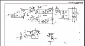
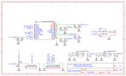
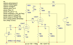
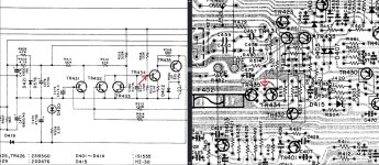
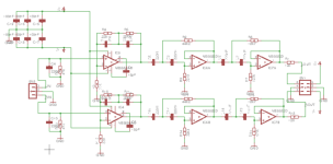
Here's the Schematic, the LED is in parallel with the spot for a resistor, in order to be somewhat universal, I'm likely using a bypassed resistor-
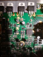
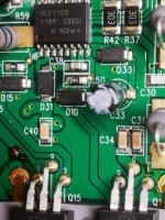
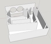
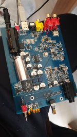
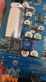
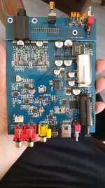
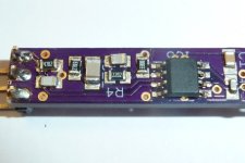
And here's some pics of the 100mm square PCB, only change is that I rounded the corners, added a capacitor across R9 for feedback compensation if needed, and ordered them in purple. The PCB allows pentode, triode, or UL connection-
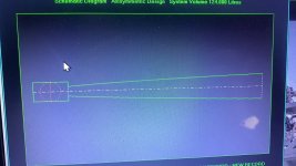
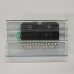
Here's a multi-layer view of the 50mm square power supply PCB i have coming as well-
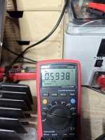
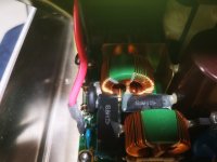
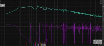
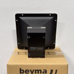
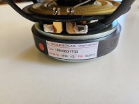
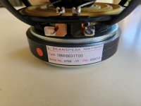
Transformer specs (generic black chinese units, no frequency graph)-
REHOC Inductance Value: 12H
Primary DC Resistance: 315 ohm
distance of mounting holes: 72 mm
colour: black
Material: metal
Size: 60x55x50mm
Weight: .41kg
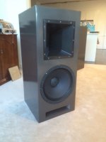
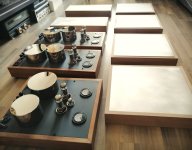
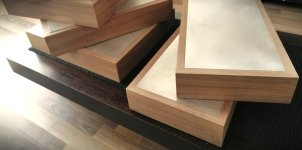
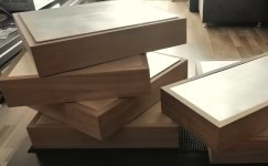
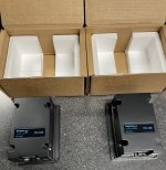
They arrived very beat up and dented, and I received a refund, in addition to that, I got to keep them. Some work to clean up the dents and some hammertone paint to cover the imperfections should make them perfect for a prototype build. Reviews on them were found that explain them to work well within the 4-5 watt power level, and they allegedly have adequate frequency response as well.
My chosen operation point for the EL84 is 5K load, 250 volts plate to cathode, and a bypassed cathode resistor, value to be determined by the choice to run either pentode or triode. Going to likely go off the datasheet values and adjust as needed for the 6P14P/EL84 that I have on hand.
So my main debate here, is what to do for the main topology.
I am currently considering the following three options for overall circuit configuration-
-Pentode output, 6N2P input, with cathode feedback to the 6N2P
-Triode connected output, 6CG7 or 6N1P input, no global feedback
-Triode connected output, 6N2P input, with cathode feedback to the 6N2P
I really like the idea of triode with global feedback, but I also really like the idea of running a 6CG7/6FQ7 front end, with the disadvantage being I will not have much headroom for lower level sources. Since the output stage only needs like ~8 volts bias worst case, I should have no issues running the lower mu front end. I have many 6FQ7 cleartops onhand, and less 6N2P onhand. The lower power output of triode mode is no trouble, as this amplifier will be run near field with DIY speakers of reasonable efficiency. I'm not terribly fond of triode/pentode switching, so It will likely stay in whichever configuration I build it into unless there is a compelling reason to change it up later.
Any input?
Almost
everything I build is pentode connected with global feedback. Rarely do I ever go for something run "wide open" so I feel like I'm cheating going for zero global feedback. Last EL84 triode build I did was push pull with global feedback as well.
Thanks for taking a look!


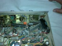
![IMG_7400[1].JPG](/community/data/attachments/1208/1208639-b550e181d46f50d282dbafbccbb0b068.jpg?hash=tVDhgdRvUN)
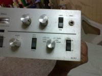
![IMG_7401[1].JPG](/community/data/attachments/1208/1208640-82e81fcabfcea317b6b616917508ac53.jpg?hash=gugfyr_Oox)