I have designed a PCB for adding an audio output to a Flipper Zero device after verifying that an I2S interface was available through the GPIO headers. This is my first post after hearing about the forums for years.
I am a beginner to circuit design so there may be a lot to fix. Any ideas to improve the design will be appreciated.
PCB design, BOM and schematic are attached.
I am a beginner to circuit design so there may be a lot to fix. Any ideas to improve the design will be appreciated.
PCB design, BOM and schematic are attached.
Attachments
-
BOM_flipper_i2s_tlv320dac3203_2024-04-19.pdf16.6 KB · Views: 68
-
PCB_pcb_tlv320dac3203_2024-04-19.zip43.1 KB · Views: 62
-
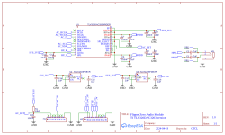
 Schematic_flipper_i2s_tlv320dac3203_2024-04-19.png23.6 KB · Views: 90
 -
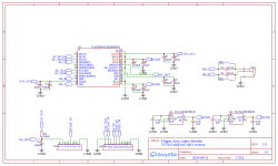
Schematic_flipper_i2s_tlv320dac3203_2024-04-19.svg184.8 KB · Views: 58
-
Gerber_flipper_i2s_tlv320dac3203_pcb_tlv320dac3203_2024-04-19.zip46.1 KB · Views: 57
Looking at the schematic .png file, it looks like the voltage regulator inputs are not connected to any supply.
I did not notice that. I updated the PCB and schematic. Thanks.