Amp out as PSU

Hello all, here is a shot in the dark. Please excuse if a stupid question. This is related to my Cub Sandwich sub build

Let's say I wanted to keep the speaker passive and use if with an outboard amp. It's a very small cab in a system sealed by passive radiators. I have designed in a heatpipe to take hot air away from the motor vent. Is there a way to bleed off a lil bit of power from the speaker terminals to power a small fan to encourage air movement in the pipe?

I.e. an active fan inside a passive speaker without any other power supply for the fan

Thanks and regards
Randy

Variations of materials for internal lining, which is the best?

What is the best internal lining for sealed and ducted boxes?
Do sealed boxes really need internal lining?
I once made a sealed box and covered it with glass wool but I was never able to check whether or not it made a difference to the sound.
For ducted boxes with subwoofers intended for deep bass, what coating should I use?

Choosing the right Class D amplifier for me

I'm working on creating a "Wall Sequencer" that let users create their own beats.
I'm trying to get a budget friendly options to build the right Audio Setup.


I'm looking at the following:

The wall will be outside in the open desert.
My goal is to have a clear sound of mostly Electronic (Techno) Instruments, so clear sound and low frequencies are important for me less than volume (power).
I believe the setup should be 2.1 speakers.

Would love to hear your thoughts an ideas on how to get the right Class D for me.

Creek Audio T50: LCD issue displays gibberish when brightness level is Off

Hi folks,
Is this an issue with the LCD itself or the circuit? I am thinking of replacing electrolytic capacitors anyway as a preventative maintenance.

Another issue I’m seeing is brightness level will not adjust (stuck on High) in the AM band.

I’ve attached schematics to the T40, similar model. The LCD model on the T40 appears to be NEC FIP7A8S, so far no luck with finding this model on google.

Thanks.

Photos of LCD brightness set to Off and Low, and T50 boards.

Attachments

  • IMG_3765.jpeg
    IMG_3765.jpeg
    365.5 KB · Views: 59
  • IMG_3766.jpeg
    IMG_3766.jpeg
    359.9 KB · Views: 73
  • hfe_creek_t40_mk3_schematics_en.pdf
    hfe_creek_t40_mk3_schematics_en.pdf
    194.6 KB · Views: 60
  • IMG_3767.jpeg
    IMG_3767.jpeg
    311.7 KB · Views: 91
  • IMG_3769.jpeg
    IMG_3769.jpeg
    722.9 KB · Views: 66
  • IMG_3768.jpeg
    IMG_3768.jpeg
    750.1 KB · Views: 63
  • IMG_3770.jpeg
    IMG_3770.jpeg
    708.8 KB · Views: 64

A simplified method to implement digital frequency division using FIR filter in Windows system

Foobar2000 released the VST 2.x/3.x Adapter plugin on 2022-11-17, the latest version is 0.12, the plugin allows VST effects to be used as a DSP in foobar2000, VST/VST3 can be used. In this way, the foobar2000 can directly call to load the FIR filter as a DSP digital crossover. It's extremely simple and plays smoothly.
Hardware:
One PC. One multi-channel DAC.
Software:
System software version: Windows7 SP1 or later. Install the sound card driver.
Foobar2000 version V1.6 or later, preferably V2.1.5.
VST 2.x/3.x Adapter Current version: 0.12。
convolver4-4vc++。 convolver4-4vc++ is an open-source, high-performance Windows application for applying a finite impulse response (FIR) filter.
rePhase。 Speaker phase linearization, equalizer, and FIR filter generation tools.

First, install convolver4-4vc++ on your system. Then, the administrator runs rePhase to generate the FIR filter file (low-pass .wav, bandpass .wav, high-pass .wav), and uses a text editor to generate the txt text file of config.
Install foobar2000V2.1.5 on the system, download and install the VST 2.x/3.x plug-in, add the VST 2.x/3.x plug-in in the DSP management of the preferences, configure the VST 2.x/3.x plug-in, add the folder where the installed convolver is located, select convolverVST (VST v2 32bit), and display the VST Effect in the pop-up format Click Filter/config in the configuration window, select the config file generated earlier, OK. Select the default speaker exclusive in the output and play it.

Audio Technica AT-LP120USB Tone arm weight?

Purchased a decent Audio Technica turntable with the stock cartridge and want to replace the original cartridge with one I have owned for many years. I am concerned with the additional weight of the Pickering XV-15 cartridge with the D1200 stylus and brush that I want to use. The weight of the Audio Technica cartridge with headshell and hardware is 15.525 grams. The weight of the Pickering with head shell, brush and hardware is 17.8 grams. The stock Audio Technica head shell and hardware is 10.7 grams.

The only information I was able to come up with is the Audio Technica can use a cartridge between 3.5 grams and 8.5 grams. I can find no information as to compliance or tone arm weight.

Haven't used it yet as I'm still trying to find more information so any help or comments would be appreciated.

Pioneer PD-106 : CD which does not turn systematically

Hi there,

I need your suggestions please. It's a curious failure, at least for me.

DSC_2368.JPG


Most of the time, we insert a disc (in perfect condition) and it fits correctly in its slot.
The disk does not turn, we hear the actuator click while it makes several movements, then nothing and the display indicates zeros.

We eject the trapdoor and its disk several times AND! the disc starts to spin, the Toc is read immediately.
We insist on the "read" button, the actuator clicks once, the disc does not turn.

We take the disc out several times, but this time we press the “play” button directly.
At some point, reading will start !
The entire disc can be played perfectly, without skipping. You can skip back and forth between tracks, change tracks at will !

As soon as you stop the disk, it will not restart. We eject the disc several times and wait for the next reading ! 👽

Notes :

  • The central motor has been checked with an external power supply and is working well. I added a drop of oil to the axle.
  • I looked at the cable connections to the motherboard, but no false contact
  • Using the multimeter on the central motor connector of the motherboard, I have between 4 and 2 volts when the disk is spinning. No voltage when the disk is not spinning.
  • Belts have been checked, no problem.
  • I also noticed that the LA6520 (ic202) is hot when the second one is cold (there are two on this card)
  • The control panel is not the cause, we see the actuator move with each selection.
  • There is nothing visually suspicious about the electronic components.

DSC_2359.JPG


- The soldering under the card was bad originally. it is poor in tin and under the soldering iron, the component legs refuse to solder.
We see in this photo the difficulty :

DSC_2463.jpg


I reworked a majority of solders correctly and even on the chips
A view of the entire board :

DSC_2464.jpg


- I also looked under the optical unit. Maybe a problem with the cms capacitors?
I didn't see anything special on the weld side.

DSC_2465.jpg


- I then saw that the rubber suspensions of the chassis were all dead !

DSC_2466.jpg


- I temporarily replaced these suspensions with plumbing washers on hand I had. No improvement.
In any case, even if the chassis is poorly suspended or crooked, the spindle remains aligned on its common chassis facing the optics.
isn't it ?
(and the CD did not rub when turning)


DSC_2470.jpg


It's only with the revision of the soldering of the board that I find the best. The disc is read once in five, instead of once in 15.


I find it hard to question the optics since when the reader works, it works perfectly.
It's a PEA1335, unobtainable or overpriced !

What can I do now ? Can you help me please ?

Doc here : https://elektrotanya.com/pioneer_pd-106_sm.pdf/download.html

Biamping 8 ohm 3-way with Denon AVR (min 6 ohm)

Hi Diyers,

I have a MiniDSP 8-channel processor, a Denon AVR-3083 (with pre-in for each channel) and a pair of KEF Q7s. I'm getting set up for bi-amping and bass management trough the MiniDSP. The Q7 is bi-ampable - splitting the woofer from the coaxial mid-hi arrangement. The Q7 nominal impedance is 8 ohm. I've just measured each driver separately (Q7 disassembled for refinishing) and they each measure 3 ohms woofer, mid & hi.
The AVR-3803's recommended minimum impedance per channel is 6 ohm.

Am I going to destroy my cheap old AVR if I biamp with it?

I'm surprised the binding post bridges seem to be series linking the drivers to get 8ohm. I would have thought positive to positive and negative to negative binding post bridges are a parallel connection. (drivers at 16ohm each...) Maybe KEF internally flipped the connections so we are getting 4 +6 ohm = about 8 ohm.

Thoughts?
Thanks

Attachments

  • KEF_Q7_posts.png
    KEF_Q7_posts.png
    28.2 KB · Views: 67

DIY Shielded Phono Cable, wire recommendations?

Hello DIYers,

I'd like to make a shielded cable to connect a tonearm (low output MC cartridge) to an MC phono stage. The phono input is unbalanced (sigh).
A few cables I've looked at are the Mogami W2534 and the W2893, both shielded quad. Another option is Canare L-4E6S sheilded star quad.

If there is a better choice of wire and preferred shield termination style for this application, just lemme know!

Desktop full range

So I had these on my desktop, and they are deceased after 2 decades of loyal service. Also a tad large, but I liked them a whole lot.

So after a lot of searching and reading (sitting close and phase, open baffle and wall, imaging, that tweeter has ehm questionable reviews apparently), I think the best and easiest option is a nice fullrange in closed box, either a Fane or a Sica, this is (probably?) as large as I can get away with next to my screen. But I'd like to avoid an absolutely huge box.

What is the smallest housing for either of these that I can get away with, is 45-47 liter good? Is it stupid to even ask and am I then better off with 10 inch drivers? About 50% music, 50% games if relevant. I just want to get rid of these crappy Logitechs. Recommend other drivers if a lot better for a small box but try and cap it at say 2×-3× the price.

SSL10455-2.JPG

Quarter Wave Absorber

Hello, I currently has an idea to dampen standing waves in a room, but I didn't find much content about it, to know if this idea would work.

So, the idea is to make a transmission line with one extremity open and the other closed, where the open extremity is the entrance of the sound from the room, so it can pass through the path that will probably have a conicity that decreases towards the closed extremity.
So, this idea came to me when I was thinking about a way to dampen or absorb low-frequency standing waves in a room.
The first alternative that came to me were bass traps, but research showed me that for bass traps to work with good efficiency from 50 to 100 or 200 hz, they would have to be very thick, in addition to the expense of large amounts of rock wool or glass wool would start to get tall.
The second alternative that came to me were the Helmholtz absorbers, but this type of absorber would not be ideal for me, as it only works with a very small range, which would make me have to make several resonators each tuned to an ideal frequency, and they also seem to me to be more complex than the quarter wave absorbers.

So, if this idea can work to dampen or absorb the stationary waves that are in the corners of my room or in other regions of my room, then could you show me content about this type of absorption or if it has ever been tried?
If this absorber idea can work, I'll talk more about my room.

I need help identifying parts on a generic Korean 5k board

I am having trouble identifying a diode that was physically burned by a cooked power supply mosfet. I could not get clear photo of the diodes in the power supply section but it looks exactly like D3 in the photo, no numbers just black on one end and a thin gold stripe. It has .6 voltage drop one way and reads open when I reverse the leads. I was thinking it’s a 4148. Any thoughts?

Attachments

  • IMG_1445.jpeg
    IMG_1445.jpeg
    99 KB · Views: 53
  • IMG_1434.jpeg
    IMG_1434.jpeg
    315.1 KB · Views: 58

Is there a reason to terminate a connection at the binding post vs. the transformer?

See attached schematic.

Audio Research terminates the feedback loop connections at the binding posts. Is there any reason they chose that vs. terminating at the transformer? The area behind the posts is cramped, and terminating the wires at the transformer also reduces overall wire length. I don't want to second guess ARC, I'm sure they have their reasons, but it seems electrically equivalent. Am I missing something?

Attachments

Ian Canada HDMIPro => Topping D90 / Ian Canada TransportPiAES and Gentoo Player

I'm new(ish) to using digital streaming. I had been successfully using Ropieee through a Raspberry Pi over the last 3 years or so. I used various DAC hats or USB outputs to various DACs.

I've now expanded my horizons, and I'm trying out some new things that I desperately do not wish to screw up.

After assembling some of the Ian Canada parts into a very basic setup, I have the Gentoo Player on the Raspberry Pi configured for USB output to a DAC. I set it up as a Roon Bridge, and it seems to be working quite well.

Now, I want to try out the other "fancy" Ian Canada parts to output the signal to the DAC properly over the various interface options.

A few (okay a lot of) questions:

First the I2S
  • I assume in Gentoo player one would select the "DAC" as Generic I2S, correct?
  • Then, as but one example, I have a few DACs. One is a Topping D90. I noticed that the pinout for the Ian Canada board is:
1713407563309.png

In the manual for the Topping, it shows the following for phase:

1713407643678.png

It would seem that I would need to reverse the phase with the D90 (or just remember to do it in Roon, I think) - no big deal.

What's odd (to me) is that it shows the following for DSD:
1713407885400.png

If I'm interpreting this correctly (highly suspect) the two (Ian's board and the D90 with DSD) cannot match. I can either have the phase reversed or the channels reversed, correct? I don't play a lot of DSD, but I'd like to have it set up properly.

It seems like it may be easiest to change the DSD to DSDR Data to get the channels correct. I can leave the phase alone. It would be inverted for both types. Then, I can just leave the phase inverted in Roon, if I actually care at all about absolute phase... which... I don't really, but...

OR

Are those settings independent of each other? i.e. if I swap the phase in the preceding step, it ALSO applies to the DSD?

I can test all of this, but it would be nice to not need to fool with testing phase.

So, if anyone knows, I'd be grateful.

-------------------------------------------

Next the AES

Onto the one that I really don't have a clue about... Gentoo Player with the TransportPiAES.

Do I still leave the "DAC" in Gentoo Player as generic I2S when I swap over to that?

Also, does anyone know how to use the Ian Canada I2S and the AES boards in a stacked configuration? I'd love to have both options permanently mounted, so I don't have to swap back and forth. However, the Masterclock from the Fifopi can only go to one thing, I think. Any advice is appreciated.

Just getting the Gentoo Player set up and running was a monumental task. In hindsight, it's easy as Pi :joker: It just had a steep learning curve for me. It's playing now, and it hasn't glitched, so... I'm leaving it alone... until I may need to change it for the AES board...

:cheers:

Edited to insert thumbnails vs. have the massive pics.

Telefunken E88CC Variants

Hi all!

I recently acquired a project preamp without documentation which uses six pentodes dual triodes (two in phono stage plus four in linestage).

I assumed all would be the same E88CC, and prior to turning it on, proceded to test the tubes on my TV-7U/D. Four are Telefunken, one Siemens, and one sans-branding (likely Chinese).

When I began testing, two showed no conductivity for both triode sides, which led me to question whether they were in fact E88CCs. Of course they lack markings other than the Telefunken diamond and country of manufacture.

What's odd is that the two mystery tubes were not in the phono stage, but instead within the linestage section, which relies on matched pairs for the two channels.

Attached is a comparison of the tube in question as well as a known, labeled Telefunken E88CC. The known E88CC has a getter plate supporting the halo post, whereas the tube in question does not. I'm not familiar enough with 9-pin tubes - much less Telefunken models to identify whether this is just another variant or a different tube altogether, so pitching this out to the experts 😉.

In the attahed images, the known E88CC is the one with gold pins and the mirror image of the number "11" inside its diamond on the underside.

Thanks!

Attachments

  • 20240509_202921.jpg
    20240509_202921.jpg
    437.3 KB · Views: 173
  • 20240509_203028.jpg
    20240509_203028.jpg
    408.3 KB · Views: 159
  • 20240509_203101.jpg
    20240509_203101.jpg
    336.5 KB · Views: 145
  • 20240509_203355.jpg
    20240509_203355.jpg
    333.2 KB · Views: 142
  • 20240509_203531.jpg
    20240509_203531.jpg
    386.4 KB · Views: 151

Acoustat Interface MK-121-2 - Minimizing the Bias Transformer Hum Noise

Preface
  • This report is a follow-up to, "Acoustat Magne-Kinetic Interface MK-121-2 - A Successful Restoration" https://www.diyaudio.com/community/...ace-mk-121-2-a-successful-restoration.404764/
  • As stated in this restoration report, "Initial Symptoms. When powered up, annoying hum noise coming from both interfaces." This noise issue was addressed in section "Minimization of 50 Hz induced hum noise" accompanied by Figures 19 and 20 in the report, whereby applying synthetic rubber sheeting to the chassis was effective in reducing the hum noise.
  • However, I was intrigued by the comment from Mr. AAM from his review of my report where he kindly replied with, "And speaking of the bias transformer, later units had the transformer mounted on rubber grommets, alleviating the "chassis hum" you experienced."
  • As these are my only pair of Acoustat electrostatic loudspeakers having purchased them new in 1980, I would never have known about this subsequent change to the transformer mounting. So, thanks to Mr. AAM for sharing this information, it got me thinking!
Purpose
  • While the initial restoration report addressed reducing the hum noise, the purpose of this report is to minimize the noise vibrations at its source.
  • Without having information about how the transformer mounting was changed in subsequent production or the parts involved, another purpose of this report is to share with our members an inexpensive solution using commercially available parts.
Anti-vibration method
* Initially I experimented with grommets to modify the bias transformer mounting, but the most effective result came from using rubber anti-vibration studs to isolate the vibrations (Fig. 1).
VD1-1510M4_VD1-1515M4.jpg

Figure 1. Elesa VD1-1510M4 (left) not used, and Elesa VD1-1515M4 (right) used in this installation.
  • Two vibration dampers are required for each bias transformer, or total 4 for the pair of speakers.
  • Of the two series of vibration dampers purchased, VD1-1510M4 of rubber height 10mm and VD1-1515M4 of rubber height 15mm, I decided to first try the VD1-1515M4 as it had the softer spring constant (Table 1). In the event of insufficient clearance between the bias transformer housing and the high-voltage board with the VD1-1515M4, then I would change to the lower profile VD1-1510M4.
  • An M4 thread type was chosen as the M4 diameter was close to the diameter of the original mounting hardware, whereas the next size up M6 would require enlarging the chassis holes.
Table-1.png

Table 1. Specifications of Elesa Type VD1 Rubber Vibration Dampers - dimensions in mm.

* A full set of specifications for the VD1 series can be obtained from the attached specification sheet. An optional stainless-steel version VD1-SUS is available for wet or corrosive applications but isn't needed here.

Preparation
  • Safety. Ensure the AC power cord is disconnected, and the high voltage circuit has been fully discharged.
  • A consequence of the rubber damping material is it isolates the earth connection between transformer housing and chassis. Proper grounding is very important, both for safety and to complete the connection to the bias high voltage.
  • To re-establish the ground connection a small wiring harness was constructed (Fig. 2).
Harness_b.jpg

Figure 2. Pre-assembly showing wiring harness for connecting both ends of each VD1-1515M4.

Pre-assembly_a.jpg

Figure 3. Partial assembly, VD1-1515M4 pair and wiring harness attached to transformer base.
  • The inside surface of the interface's chassis was lightly sanded around the mounting holes to ensure a bare metal contact with the grounding wire lugs.
  • Finally, the bias transformer with wiring harness and anti-vibration studs was installed back in the interface using M4 fastening hardware (Fig. 4).
Assembled_d.jpg

Figure 4. Bias transformer reinstalled with new VD1-1515M4 pair and ground wiring.
* Fortunately, this installation using the VD1-1515M4 pair allowed just enough clearance between the bias transformer housing and the large 50 K ohm resistor (Fig. 4).

Results
  • After installing these parts and upon powering up I was pleasantly relieved all transformer hum noise is gone, both interfaces are now dead quiet. Considering the parts cost less than $5 per interface this was a worthwhile modification.
  • Previously when placing your hand on the interface chassis you could feel the vibrations, but this is greatly diminished now.
  • Regarding the initial approach of attaching synthetic rubber isolation sheets to the chassis, this was left in place as it does no harm.
  • Side note, while the reduction in hum noise was clearly apparent, I was not expecting any changes in the audio sound quality. But there is a very subtle improvement with a clearer, more open sound. I don't think I'm imagining things as I have owned these speakers for 44 years and am accustomed to their amazing sound quality, on the other hand I cannot quantify in measurements what I have heard. While it's difficult to say, one theory might be the previous mechanical vibrations throughout the chassis impacted the performance of different components, whereas these chassis vibrations are now considerably diminished.
Final notes
  • Why it took me so long to act on Mr. AAM's comment regarding transformer isolation? To be honest the biggest priority after restoring the interfaces was repairing the multiple broken stator wire joints, documented in "Acoustat Stator Wire Repair: Hints and Lessons Learned" and this effort took over a year to complete before I could address the transformer hum. https://www.diyaudio.com/community/...wire-repair-hints-and-lessons-learned.404881/
  • As mentioned, I purchased two series of vibration dampers, VD1-1510M4 of rubber height 10mm which I kept as spare, and VD1-1515M4 of rubber height 15mm which I installed and documented in this report. Should one day the VD1-1515M4 rubber become soft and the bias transformer begins to sag, my plan is to change to the lower profile VD1-1510M4 having a higher spring constant (Table 1).
  • While not documented in this report, other makes of similar anti-vibration hardware could give similar results.
References

Attachments

Military-Grade 814 Valves for Sale

Fellow DIYers! I am reaching out to you regarding a unique collection of 814 valves that I currently possess. These valves were acquired from France some time ago, and I have meticulously preserved them since then.

However, as life often leads us down unexpected paths, my circumstances have shifted, prompting me to reassess my priorities. Consequently, I find myself in the position of needing to part with these valves.

I am posting here to inquire whether you might be interested in acquiring this collection. The valves are in impeccable condition, having been carefully maintained, and I believe they could be of value to someone with a passion for such items.

Given my impending relocation to another country, I am eager to find a new home for these valves. If you are interested or require any further information, please do not hesitate to reach out to me.

You can read more about this tube here: https://www.bartola.co.uk/valves/2013/11/23/814-se-a2-amplifier/

Thank you for considering this opportunity.

Attachments

  • 1.jpg
    1.jpg
    431.9 KB · Views: 89
  • 2.jpg
    2.jpg
    485.5 KB · Views: 89

DIY KEF Blade Coax + Dayton RS180 midbass array in baffle wall

I have 3x KEF Blade Coax drive units that I want to use in a new setup in a new house, together with 8x Dayton RS180 per side in a baffle wall.
(I have 3 of these nice coaxes, so there will also be a center speaker with the same setup but with only 4 RS180 mid)

Does anyone here know how to calculate spacing and possibly distance from floor and ceiling, and possibly have general thoughts about solutions?

Appreciate feedback and discussions!

My thoughts are in this way to solve a lot of the room nodes in the elevation plan. Split frequency will be considered, but around 4-500hz possibly with some overlap.
Originally Kef Blade is shared at 320hz, but I personally feel it is a bit low. There will be a subwoofer to take the bass area.
I have a Minidsp OpenDRC-DA8 for active crossover incl FIR.

See picture for alternative placements of mids.
In one set-up, the coax is at a height of approx. 1.25m, which I feel is somewhat high compared to the approx. 1m sitting position?

IMG-8715.JPG

Attachments

  • Baffelvegg alternativ.png
    Baffelvegg alternativ.png
    11.7 KB · Views: 356
  • IMG-8721.JPG
    IMG-8721.JPG
    395.6 KB · Views: 404

A Schade feedback PP design for GU50 tubes.

Hi All,

As I was tidying up my workshop, I naturally came across an old Music Angel XD-800MkII for EL34's that I'd bought as a DIY project, without tubes, but with case and transformers. GU50 was (is!) the tube I wanted to use.

So I'd merrily started this about a decade ago, but then got distracted onto something else, and never managed to get back to it. As such, it needs tidying up, I.e populating with tubes, and a circuit, etc.

So the original Music Angle (KT88) schematic floats about, and there's the Dynaco ST70 design which is nice, but that's all been done before, and my original concept was to build a local feedback PP, due to the wonderful sound from my local feedback SE.

Anyway, if I just built old stuff, where would I be? Surrounded by nice, working things? The horror..

So anyway after a few false starts and dead ends (LTPs, I'm looking at you!), this is what I came up with. LtSpice only so far.
The 'slightly unconventional' anode resistors for the 6AU6's (which I'm pretty sure I have in stock, from an old raid on a Tek 545b) to B+ is to give it a 'more CCS like' anode load, without having to add Yet More Bits'.

Caveats: I'm not 100% sure of the B+ voltage. Or the output transformers. Or really, the tube models.. but I've attached them.
The tubelibrary I downloaded from the tube Spice model thread, but I re-wired the GU50 model to match the tetrode symbol. I'm not sure why they don't use the pentode symbol, perhaps some SPICE vs LTSPICE thing.

So I don't get much feedback in there, 6dB or so, but I'm low on gain. But at least this concertina + Schade resists the temptation to turn into an oscillator, so that's encouraging. I could add an input stage, of course, but that's another stage, more distortion and more bits. No feedback beyond the primary, as that would be madness 😆

I did try the GU50 in triode mode too, but that was hopeless. In Pentode mode literally everything is better 😍. This design has a wonderful soft clipping too, tubes seem far more 'elastic' than MOSFETs !

Tubes are chosen as to what I already have, a sure fire method I use to ensure I can build stuff...

Please point out any easy fixes, improvements, etc, as in my ideal dream world, I'll build it and it'll be magnificent.
At some point I'll send a small AC signal into the transformers and work out what the ratios might be too. 🔬

Biasing is a bit glossed over, it's awful in the original, but if anyone has a good circuit for PP tube balance (Pot 1) and level (Pot 2) please can you post it? A handy method to casually null the PP magetic field would be cool, with absolute level setting being demoted to a 'baseplate off' think as that drifting doesn't worry me.

All comments welcome, many thanks in advance!

Attachments

How would you drive an EL509 in enhanced triode mode.

I've seen the late Tim's 859. And he uses a cathode follower. I'm not sure he would do it the same if he were to design it today. Though if a pcb was available I would have used that design. But it will become a rats nest if I build it point to point. But I digress.

How would you do it today? Perhaps a "power drive"?

Power Drive | Tubelab

I have few STU9HN65M2....

My output transformer is going to be a One Electron UBT-1.

Attachments

  • IMG20210211174927.jpg
    IMG20210211174927.jpg
    96.9 KB · Views: 983
  • Like
Reactions: TonyTecson

REL Studio II relay clicking

I powered down and unplugged my working REL Studio II for a planned power outage to repair a utility pole. Two hours later, when I turned the sub back on, the drivers relay began to click on/off. No sound could be heard except for a brief moment when the relay tried to connect the speaker drivers to the audio circuits. Needless to say, my sub is no longer working.

Visual inspection of the board show the caps to be in like new condition (no bulging or leaks anywhere). In fact the whole board looks brand new.

This sub was always left on and only turned off either due to infrequent power outages (storms) or when away for an extended time. Otherwise, the powered sub is always on.

Has anyone experienced this where only the relay is faulty or is it the power supply causing the clicking? I haven't tested any voltages yet needing advice on what/where to test. See image below for the relay picture. I can't find a schematic for this unit.

I did measure the relay's coil voltage and it fluctuates with each click - rising to a few volts then falling to zero. My digital meter is not fast enough to catch it because the click is so fast.

Thanks


Capture2.PNG

Capture.PNG

WinISD: Sealed box construction for midrange (Questions)

It was very recently that I started studying speakers and the hi-fi scene. I read in an article recently that when it comes to a sealed midrange box, the QTC has to be between 0.5 and 0.7. So far so good, but when I put any example midrange in winISD the internal volume of the box is very low... around 3 liters and I've seen examples on this forum of boxes with a volume of 7 liters. Midrange 4"

Attachments

  • 1.PNG
    1.PNG
    25.2 KB · Views: 101

BTK5-120 by YOK amp help

Good afternoon,

I've NEVER seen an amp like this one. It has 2 damaged output sections. There are no board designations and just about everything important has been defaced. The amp is sold under the name OG Audio.

The output transistors seem to be IRF640As. Can I use IRL640As?

I've circled what I believe to be the drivers... no idea what they are though... any insight??

Thanks in advance!!

Attachments

  • 20240505_192000.jpg
    20240505_192000.jpg
    459.7 KB · Views: 94
  • 20240505_192006.jpg
    20240505_192006.jpg
    500.3 KB · Views: 66
  • 20240505_192228.jpg
    20240505_192228.jpg
    347.8 KB · Views: 65
  • 20240505_192407.jpg
    20240505_192407.jpg
    280.3 KB · Views: 58
  • 20240505_192417.jpg
    20240505_192417.jpg
    273.6 KB · Views: 66
  • 20240505_193233.jpg
    20240505_193233.jpg
    370.7 KB · Views: 60
  • 20240505_193238.jpg
    20240505_193238.jpg
    420.7 KB · Views: 74

For Sale 01a preamplifier

Checking to see if there is any interest in this 01a preamplifier:

Made with boards designed by Radu Tarka

HV supply with CLC filter and regulated a la Salas
Filament bias with separate filament supplies, rod coleman boards and Mills cathode resistors
Gyrator and follower boards for low output impedance with FT-3 Teflon caps and Mundorf Silver/Gold/Oil output caps
Tubes are mounted on separate damped platforms
Stepped ladder attenuator for volume control
Included are 1x pair of 301a globe, 1x pair of 201a globe and 1x pair of 01a ST

I've always used it with one source and left the provision for 3 inputs total with a selector switch, if interested will wire it up.
PT can be used as 230V or 110V

SOLD

Attachments

  • tempImagedr431q.gif
    tempImagedr431q.gif
    1.8 MB · Views: 345
  • tempImagegKlrbQ.gif
    tempImagegKlrbQ.gif
    1.5 MB · Views: 195
  • tempImageTaIPwO.gif
    tempImageTaIPwO.gif
    1.1 MB · Views: 184
  • tempImage5MIXmu.gif
    tempImage5MIXmu.gif
    1.2 MB · Views: 161

Help identifying resistor on KEF SP1052 dividing network (KEF Corelli)

So, opened up a mint condition KEF Corelli speaker set. Manufacturing seems to be Mar-May of 1978 based on the stamps on the driver (1974), Dividing network and enclosure.

Everything looks in great shape, just looking to replace the Caps and spotted the resistor starting to fur out. W22, 3RO.

I believe the 3RO means 3 Ohm resistor. Is the W22 the wattage? Google tells me it's a type of wire-wound resistor.

What would be a safe wattage/power rating to not blow/damage the T27/B200 drivers.

Thanks in advance!

For anyone looking for the SP1052 dividing network photos:

IMG20240509113824.jpgIMG20240509113850.jpgIMG20240509114055_01.jpgphoto_2024-05-09 13.33.53.jpeg

Thread split from Hornresp: When to use a PAR segment

So, the last four or five pages or so of this thread are just argumentative discussion over the suggestion that Hornresp should default to assuming PAR segments unless specified otherwise by the user? Wow ... 🙂

No. It's about modeling a pyramidal enclosure and then building a 2 parallel sided enclosure.

Now, HR defaulting to PAR instead of CON could help with the learning process. I'm willing to bet most 1st time users see the default CON segment and THINK it's OK to model all their 2 parallel sided enclosures that way.

CON should tell you if your enclosure will not look cone shaped internally (since folks like to build enclosures with wasted space), then don't use it.

Sometimes, things are simple as 1+1 = 3...🤣😂

For those people that don't get it,

1, +, and 1 are 3 individual items, words, spaces, etc

Shoot, maybe CON is OK since the 3 word also means a form of deception...thinking a 2 parallel sided enclosure will perform like pyramidal enclosure model is a falsehood.

Can we improve resolution of quasi-anechoic speaker measurements using adaptive filtering techniques: A study

This thread explores the use of adaptive filtering/beamforming techniques to get better resolution quasi-anechoic speaker measurements.
Some of the initial ideas about using such techniques is motivated by the work done around here: https://www.diyaudio.com/community/...d-scanner-on-a-shoestring.318151/post-7038419 by @aslepekis and @Kravchenko_Audio

In this thread, I intend to explore more along similar lines and use more beamforming algorithms to see if something works out. Atleast we'll get to know some of the limitations of such techniques.. 🙂
@fluid has been helping me with some initial ideas, papers, and motivation to pursue this kind of exploratory work.. 🙂
In below posts I intend to update the results of experiments (and eventually the Matlab code I have been writing to do all this)

For Sale 2SK1530 + 2SJ201 - 4 pairs (originals from tme.eu)

I am selling 4 pairs of 2SK1530 and 2SJ201 Toshiba originals bought many years ago from tme.eu.
They were for a project with lme49830 that I wanted to make but never had the time.
If interested, I also have lme49830.
Price is 80 euro for all 4 pairs plus shipping.
I ship only in EU, the shipping cost is between 15 and 30 euro depending on the country.
Thanks!

PXL_20240510_171701760.jpgPXL_20240510_171743352.jpgPXL_20240510_171859355.jpg

convert midrange speaker to 6.5" subwoofer

I have a midrange speaker with a neodymium motor and my question is surely stupid, what should I modify to convert this midrange speaker into
a low resonance woofer to be able to make low frequencies? Taking advantage of its neodymium motor and 2" coil. The midrange in question is this: https://maverickscustommotorsports....-back-carbon-fiber-neodymium-midrange-speaker
I had thought about opening the closed chassis and changing the suspension for another, but I suppose the coil and its travel would also play a role.

3-way to 3.5-way conversion

I have a plan to convert my speakers from originally 3-way to 3.5-way system. Each speaker consists of a 0.75" tweeter, a 2" dome midrange, and two 10" woofers.

I use VituixCAD2 for the simulation tool. Let's see the original crossover circuit and its response. Specification of each driver is indicated in the schematic.

original.png


The target of this conversion is to split operating range between two woofers. One woofer, the upper unit, will be responsible for lower midrange and bass, while the other, the lower unit, will cover only for bass of lower than 100Hz region. It's just like the integrated subwoofer concept.

New schematic is shown below.

parameter.png


The plan/concept is to disconnecting lower woofer first, then the SPL on woofers' region will drop, some attenuations on midrange and tweeter may be required. After that, reconnect the lower woofer and build a new crossover for it (L2) along with tweaking original crossover (L1, C1) for the upper woofer.

The problem is I had tried random values for L1, C1, and L2 many times in the simulator, I couldn't achieve the target though. I need advice which directions should be applied to those parameters to achieve the target. Or is my objective achievable by this plan?

Rullit Aero 9

I just received rullit aero 9 and a power supply from Vietnam. I sat them on my office desk and listened to them. Ok not deep bass but not bad but have a kind of fluffing noise. So yesterday the weather was kind and I took them to my listening room in the garden and fitted them into my quarter wave boxes. I have also rullit silver lab 8 and aero 8 both sound great. But these aero 9 sound distorted something awful. Any thoughts on this appreciated. The seller sent me a video of them in his room and sound ok and I don’t doubt they were ok when they left him. Could something happen in transit to cause this issue.

Whammy potentiometer

Hi everyone.
I'm rearranging the internal layout of a Whammy (headphone amplifier)
Originally it was equipped with a 50k rk27 potentiometer.
I also have a 10k rk27..
Could be better?
Probably a lower input impedance captures less noise, but I wouldn't want any negative interaction to form with the 2.2k input resistors and the 1uf capacitors that follow.
Advice?

Attachments

  • Screenshot-20240419-173250-Chrome.jpg
    Screenshot-20240419-173250-Chrome.jpg
    85.4 KB · Views: 160

Audionics of Oregon BT-2 Preamplifier Overhaul

Hello all-

I recently picked up this Audionics of Oregon stack for cheap - a BT-2 preamplifier with a PZ3 Series II amplifier.

stack.png


They were sold as-is, and upon testing, I found the preamp to sound very good, but it exhibits the classic snap-crackle-pop-fizz of failing silicon.
The folks at Audionics decided to pot the circuit boards, presumably to protect their IP. Unfortunately, this made them absolutely impossible to service. They were violating right to repair way before it was cool!

20240224_151329~2.JPG
20240225_145826~2.JPG
20240225_145835~3.JPG


I tried replacing the two small signal transistors that weren't potted, but they didn't have any effect. Based off of the 8-pin packages visible from the bottom, this looks like a simple op-amp based line amplifier to me. Even if I could service the board, finding these ancient op-amps would be a tall order in itself.

I love the simplicity and weight of the chassis, and the switches/pots are of very high quality, so I would like to revive this preamp by installing modern boards.

What are some favorite DIY preamp boards of the forum? I think I would like to keep it op-amp based to keep in the spirit of the original circuitry, but am open to discrete ideas as well. I want to buy boards in kit or pre-assembled form, not looking to break out the proto board this time. I don't mind buying PCBs and parts separately though.
I would like to replace both the line and phono boards, so suggestions for both are welcome.

Thanks!

winding air coil inductors - removing springiness?

G'day Guys,

I am winding some inductors for the output thiel network on an amplifier:
5uH.

I've gone with 18awg wire. According to this calculator https://www.circuits.dk/calculator_single_layer_aircore.htm
I need 18 turns on a 25mm mandrel.

After winding the copper wire around my mandrel (a 25mm electrolytic capacitor) the wire wants to 'spring' back and loosen up.

Any suggestions on how to get the thing to hold its form nicely so that I can dip it into some epoxy?

problems with REW measurements - suspected amplifier malfunction

Hi everyone .
So far I have used the equipment listed below to take measurements of my Karlson K12 prototype kabinet. I have always used a single speaker (12" woofer) without crossover and without tweeter, sweep frequency 20-2KHz:
Laptop PC combined with REW software, e-mu 0404 sound card, om1 line microphone and finally marantz pm510dc amplifier.
Lately I haven't been able to take measurements anymore and I would like some help to understand where the problem lies.
when I start a measurement, REW detects no signal, or very low signal, as you can see from the attached image. Despite this, I hear a very loud noise coming out of the speaker. I suspect the amplifier is the cause but I can't be sure.
I tried listening to music but what I hear is unpleasant. when everything worked well I always took the measurements with the amplifier's EQ active but with all the levers set to zero. now I can no longer use this function and it has been disabled with the (EQ defeat) button because otherwise a horrible noise will be heard. lately you can't even hear the noise anymore but a protection is triggered (I imagine this) and you can't hear anything.
there is another thing that I don't understand, REW doesn't work right even though the sweep volume is high. perhaps some protection is triggered within the software because what comes from the microphone is wrong. I suspect the problem lies in the amplifier's EQ circuit.
what do you suggest?. Hello and thanks

Attachments

  • rew.JPG
    rew.JPG
    121.4 KB · Views: 127
  • 1.jpg
    1.jpg
    335.1 KB · Views: 117
  • 2.jpg
    2.jpg
    268.3 KB · Views: 98
  • 3.jpg
    3.jpg
    136 KB · Views: 120

Is this a gimmick?

Scanspeak came out with these. It’s hard to believe that an oval voice coil would have less distortion than a round one does. I guess that’s why they aren’t showing distortion specs. Distortion probably sells fewer speakers than style does. I have no doubt they have low distortion, but how much does the voice coil shape matter?

1715128949761.jpeg

A little tube porn: "Gossamer" VT-62 (RAF) SE A2 amp

Finally built some amps using the VT-62 (RAF) triode (basically 4304CB or DET12, or 834 with a B4 base). Conservatively about 15 watts out. Hot as heck.

Driver is a triode/pentode with the pentode a DC coupled cathode follower to drive the VT-62.

Details at http://www.pmillett.com/gossamer.html

PXL_20240420_190407026.jpg

Curve tracer suggestions

Good morning tube amateurs, I'm looking for curve tracer hardware design suitable for connection to external oscilloscope, in order to perform measurement on sweep tubes such as the marvelous posted in #1413 dated 2021-02-14 (page 71 of "Those Magnificent Television Tubes"). Any suggestion for schematics or second hand equipment? Something equivalent to Tektronix 570 but with external oscilloscope. Thank you

Turntable/phono stage grounding issue

Hello!

I can't seem to ground my turntable to the cairn boost phono stage without attaching the GND to one of the phono inputs. It massively reduces the hum but it doesn't entirely get rid of it (hum is only audible when there's no music and I turn it up a bit but it's still there in the background).

Any idea why the original GND isn't working? I've opened it up and the connection from the terminal to the board is fine.

Could it be that there is no earth wire on the kettle lead I'm using? It's not the original one as I bought it second hand and the lead is moulded so I can't check without cutting the wire.

Also is there any danger of damage to anything by connecting to the phono?

If I connect it to the GND on my old tuner it's similar to attaching it to the phono, perhaps a tiny bit less hum...could it be an issue with the deck itself?

Thanks in advance.

Longest songs

In this era of instant gratification 128 character posts and 2 minute noises that passes by "music"... you listen and enjoy long songs?

I mean, songs that are significantly longer than 10 minutes ( often studio songs will offer much longer versions in the Live versions, which I think are superior ).

I'll give you some rock songs ( classical doesn't count because by definition it's always long format ).

Pink Floyd, Echoes.
The Allman Brothers, Mountain Jam
The Doors, Celebration of the Lizard - Live

Sure, the Grateful Dead have a lot of loong songs... but most of them were "recorded" as live shows... not studio albums.

IMHO, a good long song must tell a story... take you into a real mental "trip"... bringing you up, keeping you up there and then bring you down gently...

Bourbon Barrel Speakers

Whenever my friend Brandon Boyd comes over, we listen to music and drink bourbon.

He is a vendor who did some excellent work for my company. So I built him a pair of speakers.

bourbon_barrel_5344++.JPG


In building these, I wanted to “channel” Brandon. He loves bourbon. And since he’s got enough personality for five people....

brandon_boyd_cowboy2.jpeg


....the obvious solution was to make him a 10” subwoofer out of a bourbon cask (18 liters volume, purchased on Etsy) with full range satellites using front and back panels made from 4” wide bourbon staves; also purchased from Etsy.

bourbon_barrel_4580.JPG


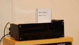
He was absolutely THRILLED - this is a photo of him seeing them for the first time:

brandon_bourbon_speaker_delight.jpg


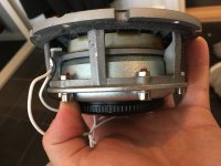
Staves from standard bourbon barrels are ~4” wide and 34” long. Perfect for a slim set of satellites built around a 3.5” Tang Band full range driver. Carpenter Seth Cothron fashioned these into a set of full range back-loaded horns. They cross over at 130Hz to the 10” subwoofer using a MiniDSP 2x4HD.

bourbon_barrel_4582.JPG
bourbon_barrel_4583.JPG


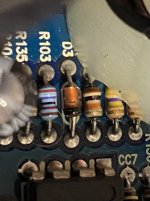
The driver for the satellites is a Tang Band W3-871SC wideband unit. The back of the satellites features a tweeter, a Dayton ND20FA-6 3/4" Soft Dome Neodymium for rear fill. Tweeter crossover a 4 uF capacitor. I added a 100uF capacitor to protect the Tang Band 3.5" full range from mishaps.

bourbon_barrel_tb_horn_satellite.jpg
bourbon_barrel_4595.JPG


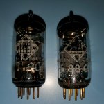
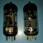
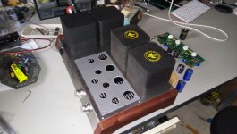
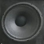
The subwoofer is a GRS 10PT-8 10" in a reflex box tuned to 45Hz with a 3” Precision Port flared port tube. Woofer on one end, port on the other. A 4 channel x 35 watt Yamaha amplifier does a splendid job. If you drive the satellites with tubes, they sound even better.

Active crossover frequency is 130Hz. The back loaded horn (designed using the old Transmission Line program by Leonard Audio) has the driver placed at the optimum point to cancel the 3xFb resonance.

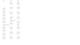
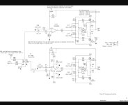
This is the drawing carpenter Seth Cothron used to make the satellites:

TB+3.5+Transmission+Line1.jpg


The front and back panels are made from staves, which are naturally curved. They are also extremely rigid and inert.

The semicircle on each side at the bottom functions as the port for the horn. These horns are deliberately designed to produce a 7-10dB peak at 150Hz, so combined with an active crossover that kicks in at about 200Hz, the 3.5” driver with its very limited displacement gains maximum leverage with little strain. It can produce significant output with little power and very little excursion.

I love using back loaded horns with small full range drivers. These speakers have a huge sound and soundstage that belies their tiny size. They simply sound far bigger than they are. I have built many larger and more sophisticated systems, like the award winning Live Edge Dipoles. But I took these to the Dayton 2023 Speaker Design Competition and got very positive comments from the judges.

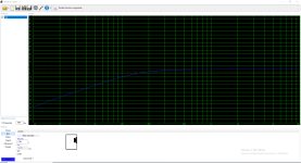
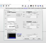
This is a frequency response of both near field output of the horn and near field output of the Tang Band 3.5: driver, overlaid on top of each other:

brandon_boyd_sat_nearfield+port.png

I am extremely happy with this. What these curves say is: below 1500Hz the horn exit produces most of the output and above 1500, the driver takes over. It's not possible to exactly match the levels of these curves. The system sounds fantastic with almost no EQ beyond the basic crossover and 45Hz bass boost for the small reflex sub.

The rear firing 3/4” tweeter compensates for the narrowing dispersion of the full range driver and adds a LOT more space and air to the soundstage.

bourbon_barrel_5385.JPG

They sound fantastic about 3 feet out from the front wall.

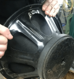
In theory, a bourbon barrel is a fantastic speaker cabinet because the barrels are made of white oak, they are extremely rigid and again in theory they are sealed.

In real life, bourbon barrels are charred. (This impacts the flavor, color, and overall character of the bourbon, as it interacts with the wood during the aging process.) It also makes speaker building a little messy, and I found out a “retired” bourbon barrel has lots of leaks which need to be sealed before it properly functions as a speaker.

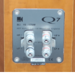
I mounted speaker terminals in the bung hole, and purchased 1.5” feet to suspend the cabinet above the floor. I also installed a handle on the top so it could be carried.

The MiniDSP EQ is pretty simple: The satellites sound great with nothing but a 24dB/octave filter at 200Hz... which, because of the rising response of the port around 150Hz, makes for an effective acoustic crossover at 130Hz. The subwoofer has a 12dB/octave slope at 120Hz and a +7dB peak at 45Hz (the port tuning frequency) with steep rolloff below. I have attached the family of DSP EQ XML files for this system in a ZIP file.

These can play plenty loud and have superb stereo imaging, huge soundstage, a full body and depth that you simply do not expect from a 3.5" driver.

partsexpress_bourbon_barrel_judges1OH+.jpeg

Above: My demo at Parts Express 2023 Speaker Design Competition. They judges and audience had many positive comments. Someone even asked me, "Are you an artist?".

Happy Wife

The wife of another friend came over to my place while I was building these. She walked in the room and FLIPPED OUT. (How often do women FLIP OUT over speakers???) She said "You HAVE to build me a pair for John for Christmas" so I obliged.

Two of these Bourbon Barrel Speakers now exist in the world. I encourage you to mint your own version of these. Very fun, great sound with a huge Wife Appreciation Factor.

Attachments

pair of identical speakers but one of the two works in reverse

Hi everyone .
I built a cardboard model because an image is essential to ask my question, otherwise it is difficult to explain using only words.
in the photograph you can see two identical speakers placed in a casing. for the moment let's establish that the box is closed and leave aside the type of loading.
we connect the two speakers to the same channel of the amplifier but to one of the two we apply the reversed polarity.
when one driver pushes forward the other pushes backwards and vice versa.
what happens inside the casing and on the cone of the two speakers?

IMAG0039.jpg

Vacuum tube - Electrode Insulation importance for audio?

I am looking to buy some NOS vacuum tubes for audio purposes and there is more than one version of the vacuum tube.

What is Electrode Insulation and does it have any purpose for audio purposes?

Electrode Insulation (min)
Grid to all other elements: 500 Megaohms
Plate to all other elements: 500 Megaohms

Versus

Electrode Insulation (min)
Grid to all other elements: 100 Megaohms
Plate to all other elements: 100 Megaohms

DHT-buffered NOS-dac

Hey,

OT:HiFi-friend Bardis had a Monica TDA1545 NOS Dac he wasn´t to impressed of. So I redesigned the DAC part with advices from T.

Anyway, Andy Evans mentioned the small DHT double triode 3A5/DCC90 some years ago. So I decided to try it when designing a buffer for Bardis redesigned NOS-Dac. As he has a lowZ input preamp a hybrid configuration was chosen. A Slagle bifilar transformer would be great but then Zout would be in the ballpark of 6kohm and loaded with at least 20kohm. The heater CCS should later be exchange for discrete components.

There where no sign of microphony. The only thing made was that the tubeholders where mounted on a metal plate that then was mounted to the chassis with extremely soft silicone cushions.

The DAC was shown and demonstrated at Hififorum´s DIY-show in Gothenburg some week ago. Great success!

Pictures: Schematic, inside view of Bardis soon to be ready DAC, the readybuilt DAC playing at the show in Gothenburg.

Attachments

  • BARDIS3A52[1].png
    BARDIS3A52[1].png
    81.7 KB · Views: 946
  • innei.jpg
    innei.jpg
    177 KB · Views: 889
  • DACbild.jpg
    DACbild.jpg
    11.8 KB · Views: 826

Jjasniew's Guitar Amp from Hammond model LA Husk

A place to document whatever it is I might do with this gift from a fellow player. I've got a grounded 3-wire cord in place to see if stable, bringing up/down on a Variac. I made the absolute sophomoric mistake of plugging my new set of Soviet "6V6 equivalent" tubes in it, plus another two 6V6 from the tube box, to see what would happen. Surprised I even had 8 6V6s on hand.

Ended up red-plating two of my new Soviets, instead of the two randos from the tube box - my idiocy / luck with the sox I happened to plug them into.

Replaced C10 / C11, which just one was leaky enough to put zero negative bias on the tube set that red plated. They were some kind of "Vitamin Q" look-alike, while C19 / C20 for the bass side are more std wax dipped jobs, that arent leaking. ~-15V on all 8 6L6 grids now, of course pairs tied. She idles fine now at full AC line.

This amp has the cool cathode windings in both OPTs, in the kinda-sorta McIntosh vein. Unsure what the coils L1, L2, L5 and L6 do, never seen anything like it. One of the pins of the protruding connector had 250V on it, so I snipped off that wire connecting through a large WW resistor to the B+. It's so nice to have found the schematic online, courtesy of captain-foldback.com which I've posted below. I'll mark it up as I go along.

T1 is an interesting bit under the hood - it's big. I've always wanted to do a guitar amp with transformer interstage coupling; maybe it'll work for that. But, what a gift; all I need to do is come across a spring set and connect it - there's my reverb channel with it's own amp / speaker. I have to wonder if this tranny once drove the big, tall Hammond necklace reverb, or one of the more ordinary 18" cans?


1715311741966.png

Ceramic capacitors as diode bypasses for power supply rectifier

According to Morgan Jones's "Valve Amplifiers" book, there is need to bypass diodes connected to a transformer output to absorb field energy while all diodes are in cut-off ( +/- 0.7V around zero crossing). He suggests using 10nF film capacitors. I have a bunch of 10nF/1000V ceramic disc capacitors I use as switch bypasses, could these be okay? A film capacitor seems overkill across a diode, and aren't ceramics better suited to absorb fast transients?

About BJT picking

Hi ! sorry for my basic question
I would be very grateful to get a kind advice about how to select bjts to be used in line preamp and line level buffers
I am playing with LTSpice I say playing because i just try different values and voltages without really understand what i am doing
Anyway i have noticed a certain change in THD performance changing bjt Strangely some smd parts seem to perform better than three legs parts
Are there better parts for a same purpose ? what i have to look in a datasheet ?
Thank you all very much indeed

GAS PSP3500.1d going into protect

Hello, repairing my brothers PSP3500.1D (or trying to). Issue in the title.

Tools I have: Multimeter (has diode mode, beep, etc), soldering iron

How it happened: He was listening to music at a low volume, shut off the car and went to the shops, when he came back the amp was dead.

What I've done: Opened it up, found a IRFB7437 with the drain leg melted (see image below). Its 4.7ohm (4R7) gate resistor also was dead. Replaced both, still goes into protect.
IMG_20240420_203345.jpg


Diagnostics:
There is no short between the RCAs and speaker outputs
There is an increasing resistance (goes from ~0 to ~135ohm) between the power and ground terminal.
There is an increasing resistance (goes from ~0 to ~135ohm) between the drain and source (2nd and 3rd pin left to right) of all these fets (see image)
Rest of the fets seem fine
IMG_20240426_200320.jpg


Other side of the amplfier:
IMG_20240426_205827.jpg


I hope we will be able to find the issue, thank you in advance.

Replacement "plate amp" for a REL Sub

After trying to find a way to fix a REL Studio II plate amp (300 watts), I am thinking of just replacing the amp with a new one that is housed outside the enclosure and wired through the plate to the drivers. Can someone recommend a high quality amp (similar power) that has some of the controls the REL has? I won't be able to use the high impedance inputs REL is famous for, but having this sub work again would be great.

For Sale Transcendent Sound The Beast kit

I have a kit of parts for the famous Beast, comprising:

36 x JJ EL509, 30 BNIB, 6 slightly used. (HotRox are selling them for £55 each.)

The 6 required input / driver valves - see pics

2 x mostly assembled PCBs - see pics. Plus the 8 electrolytics for the board without them.

All the trafos, custom wound for this application.

There is a build guide and schematics. You will have to create your own enclosure.

As mentioned above the cheapest new price I can find for the EL509's in the UK is £55 each. This obviously has a bearing on the value of this kit of parts and I am asking £2,500 plus shipping.

Photos to follow shortly.

For the LIne Array gurus

So i might have a casual client that wants a custom floor standing line array for a small performance venue that has a ceiling height that graduates from 8ft to 12ft that does mostly 3pc jazz, singer piano and occasional chamber music and an expansion of his already well established restaurant. The space is 30 ft wide so wide dispersion is important but the walls are brick so there needs to be some control. Stage is 16 ft across so close to 16ft of separation in the triangle.

My question is in the horizontal driver alignment.....i can meet the SPL needs with an MT config.........but i'm wondering if an MTM might provide better horizontal directivity? Mid to tweeter XO will be in the 1.2khz region using an 8" woofer and an AMT per section. These won't be modular.......just boxes hung from the ceiling and 18" off the floor.....no need for anything down there. The 8" woofers polar measurements show no appreciable beaming until 2khz.....pretty much omni up to the XO point. I was a little surprised by that......they have an inverted dust cap so i wonder if that has anything to do with it?
Projects by fanatics, for fanatics
Get answers and advice for everyone wanting to learn the art of audio.
Join the Community
507,708
Members
7,885,261
Messages

Filter

Forum Statistics

Threads
406,088
Messages
7,885,261
Members
507,708
Latest member
ahmadmusowwir