I've seen the late Tim's 859. And he uses a cathode follower. I'm not sure he would do it the same if he were to design it today. Though if a pcb was available I would have used that design. But it will become a rats nest if I build it point to point. But I digress.
How would you do it today? Perhaps a "power drive"?
Power Drive | Tubelab
I have few STU9HN65M2....
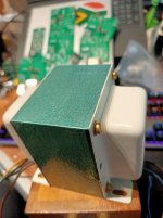
My output transformer is going to be a One Electron UBT-1.
How would you do it today? Perhaps a "power drive"?
Power Drive | Tubelab
I have few STU9HN65M2....
My output transformer is going to be a One Electron UBT-1.
Attachments
Last edited:

The past years I've been collecting various sweep tubes, planning PP g2 drive using the interstage transformers I used in a PP EL36/38 experimental setup many years ago.
Then I learned about powerdrive.
Then came the crazy drive threads.
And now UNSET and its offspring.
All this reading and pondering didn't fill my room with music, so I'm finishing up a more traditional g1 driven PP PL519, fixed g2, CFB 100W monster to blow away the cobwebs for now 😀
The downsides of g2 drive are the high drive requirements and high output impedance, so you need quite some gain, voltage headroom and NFB.
Crazy/dual g1-g2 drive reduces the drive requirements and when properly scaled is exceptionally linear.
I still want to try that out. Driven by some form of power drive.
Bas,
I've built the EAR 859 and the updated version--the 869.
In both I used a source follower based on Gary Pimm's self biased CCS.
With the 859 I built the sbccs into a 9pin socket so that I could easily swap between the pcc88 and the sfsbccs.
Everyone who heard both preferred the source follower version.
stay safe
t
About 8 Watt. According to the specs 5 Watt max power can be drawn from the screen grid. So 8 Watt should be ok to give a clean output.
Last edited:
That seems totally off , how could a PCC88 cathode follower supply that amount of power , or any reasonable power/current , in the original design ?
Sure, you also use 1 Watt resistors if exactly 1 Watt will be dissipated and use 400v Elco’s when 400v is applied. Then yes you are correct.
I was just asking if you how/measured how much current ( if any ) is drawn by G2 ... to judge myself what is needed . Not how to do it overkill 😀
That is easy. Use a resistor a dc voltage source and measure the voltage drop changing slowly the voltage or even easier: Read the specs of the tubes. Philips has nice graphs of these tubes.
But it was asked “how would YOU do it” so i answered.
BTW, i would not use the enhanced triode connection in the first place but that was not the question.
Best regards,
Frank
But it was asked “how would YOU do it” so i answered.
BTW, i would not use the enhanced triode connection in the first place but that was not the question.
Best regards,
Frank
Lampie519,
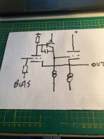
It would be helpful if you could provide a schematic of your amp. I’m with Depanatoru - don’t understand what you mean by the words you wrote earlier about 8 watts. Is this the amp output power?
Sand or no-sand; I want good sound and don’t mind a little sand if it could help 😉
It would be helpful if you could provide a schematic of your amp. I’m with Depanatoru - don’t understand what you mean by the words you wrote earlier about 8 watts. Is this the amp output power?
Sand or no-sand; I want good sound and don’t mind a little sand if it could help 😉
Last edited:
For sand there is an other forum ;-)
If i would share my design it would be off topic as it is not using the enhaced mode anyway.
But it is common knowledge that pentodes have some advantages over triodes as cathode follower.
Please read Alan Kimmel's article about his Mu Follower.
Quote: While I'm talking about cathode followers, I believe pentode CFs deserve serious consideration. A pentode CF has several advantages over triode CFs, including lower input capacitance, larger voltage swing, lower output impedance. and lower attenuation. I think pentodes are better suited for CF service than for any other use.
Sorry mate but no can do. Unlike you who must prefer metal and ceramic tubes, we love our glass enveloped tubes. You know full well that glass is made out of sand. 😛No sand!
This Svetlana Technical Bulletin provides the same information as the article Steve Morley has linked in #3.
I never got anywhere near to the 10 watts of output power the TB promises with the original design, Either the Soviet 6P45S is quite another tube than the European PL519 that I used, or the claims are based just on simulations, not real life measurements. And I think it's a no-go that the first stage's cathode trimpot has an impact on the operational point of all three tubes as well as on the total voltage gain. My reworked design avoids this and provides more plate swing for the final tube before the screen grid takes over. To achieve this, the cathode resistor needs to be lower as well as the plate impedance, which is 1.7 kohms in my amplifier.
Best regards!
- Home
- Amplifiers
- Tubes / Valves
- How would you drive an EL509 in enhanced triode mode.