AmpCamp Amp 1.6 using as monoblocks

hi,
question: I got two ACA 1.6 amps. One with power switch in front and a stereo/mono switch in back (amp1). The other has the power switch in back and no stereo/mono switch (amp2), it's just wired for stereo.
I want to use the two amps as monoblocks, each amp powering one speaker. When connecting the cables like in the build guide, I noticed less power coming out of the amp with no stereo/mono switch. Am I correct that this has to do with amp2 only using one channel for amplification, not both? And, would a solution be to use XLR outs as those seem to be wired to both channels on amp1 and amp2? Or would there be another solution that's practical.
Thanks in advance for any advice!
Martin

Two mystery tubes: Hoges ECC88 and Haltron 12AT7

A ECC88 and 12AT7/ECC81 from rebranders Hoges and Haltron respectively.

The Hoges ECC88 has a strong resemblance to Siemens tubes of the same type, like the getter installation and two-step support. But I can't recall seeing that first step metal plate being circular with no machining/cutting done to the part.

IMG_5813cut.jpg

IMG_5814cut.jpg

IMG_5815cut.jpg

IMG_5819cut.jpg


The Haltron ECC81 looks like the Philips family of tube construction. It very much resembles a Mullard (Philips branded) ECC81 I've got, but as the Haltron has four glass seams at the top this is apparently not possible. Another guess would be the Indian BEL factory who collaborated with Philips/Mullard. As a matter of fact, it reminded me of a BEL E81CC (Zaerix branded) that I brought to attention in another thread (https://www.diyaudio.com/community/threads/zaerix-e81cc.404144/). The look very much alike, except that the Haltron has ribbed plates versus smooth ones on the BEL/Zaerix.

IMG_5828.jpg

IMG_5825.jpg

IMG_5834.jpg

IMG_5830.jpg


Please chime in if you have any thoughts, suggestions!

Looking for high quality NOS DAC kit

Hello Guys,

I'm looking for a good DAC kit (or assembled).
I'm listening music in CD quality, but some frequency correction is also needed, so a 20bit or 24bit DAC would be fine.

What I already found:
  • Ladder DACs on ebay (for 65EUR or much more)
  • Some PCM61, AD1865 based products, also on ebay (about 100 EUR)

I afraid, none of them are good quality designs.

I have seen some Abraxalito DACs here (I'm sure they are all well designed DACs), but all of them were 16bit only.
Do you have any recommendations for other valuable NOS DAC kits?

This guy is doing this hobby the way I always wanted to do it

I came across this video. I'm a Newby, but when I decided to do this hobby, I always thought I'd be doing it the way this guy is, totally experimentally. I have a lot to learn to get to this point. He made a "tube tester" that let's you set up and dial-in any operating point, while simultaneously obtaining the harmonic profile you like, in real time, while simultaneously hearing it musically in real time! He is a man after my heart. I know Spice is all the rage, and my journey has taken me on many tangents. I ought to go back to what I intuitively thought I would be doing learning tubes, which is what I'm seeing in this elegantly simple video. I don't understand everything he's doing like with the triangle waves, but the ability to dial in an operation point, harmonic profile and hear the music simultaneously is amazing to me here. Worth the watch. Its in German I think, but has subtitles.

Login to view embedded media

Hello from California

I design and build tube amplifiers as well as modify and repair existing amplifiers. I've been at this since the seventies, although there were some stretches when I didn't work with electronics. I probably don't have much to contribute to this forum because it appears as though there are members here that pretty much cover anything and everything. But who knows, maybe I can help with some obscure tangents every now and then.
  • Like
Reactions: GJSoundBoy

Pumpkin Preamp - Perfect for F4

there it is
schm and render of pcb enclosed

now I'm waiting for pcb protos and heatsinks ,just to tweak some values - this time I'm lazy (or spoiled?) to make Ikebana prototype

I don't like to use nag nag protoboards where I can't see connection, contrary to Oly......pcb wizz with 100 yrs of needlepoint experience

this preamp is in fact Steen's wish, sorta half UGS bla bla
seems that this days I can't make anything what Papa already didn't

why that reminds me on old story about pigs and pearls :clown:


there is proverb in my native........"there is no bad swill for good pig"


Pink Floyd ZM

Attachments

  • thepumpkinschwcl.gif
    thepumpkinschwcl.gif
    33.3 KB · Views: 13,258

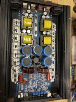
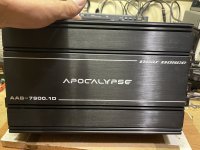
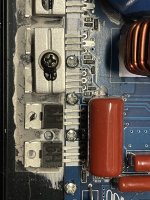
Def Bonce AAB-7900.1D Output Mosfets, etc

Hey all, looking to know what these “H9” output FETs are on this DB AAB-7900.1D are, non-destructive high side right bank failure, looks to be a single MOSFET, took a cap out near the speaker inputs as well. Any info towards finding out what they are would be greatly appreciated, I’m thinking the IRF4115 but not certain. Also would be helpful to know what others are using for the signal/zener diodes at each FET bank as I’m not over familiar with this package type 😅

🖖🏼

Attachments

  • 4AFCB18A-2ED7-4C4A-A4DF-54CE27B1D465.jpeg
    4AFCB18A-2ED7-4C4A-A4DF-54CE27B1D465.jpeg
    678.7 KB · Views: 77
  • 7718AA3A-6093-466A-92D6-642BB63CC794.jpeg
    7718AA3A-6093-466A-92D6-642BB63CC794.jpeg
    532.4 KB · Views: 71
  • 091FFB95-11C2-4350-A5AA-43CF5AFF4190.jpeg
    091FFB95-11C2-4350-A5AA-43CF5AFF4190.jpeg
    529.6 KB · Views: 75

Basis for Hofmann's law

I see people often speak of Hofmann's law when referring to a fundamental tradeoff between the size, the low frequency extension and the efficiency of an enclosure design. It is often mentionned that all enclosure types are subjected to the same tradeoff. After seeing references to this "iron law" being broken with some new driver technology by Brane Audio, I was puzzled as what they proposed (successfully or not, this is beyond the point of this thread) would only solve the problem of a driver having to work against a reducing compliance in smaller and smaller enclosures. This made me think that I misjudged what is referred to as "Hofmann's law", as I thought the theoretical basis for such a general law had to be concerned with the radiation impedance available at a certain size, irrespective of driver technology. The only "derivation" I could find for it by Henry Kloss is concerned only with the limitation tentatively addressed by the Brane Audio approach (while not a completely rigorous derivation, I believe the details can be rigorously filled in for that setting).

This leaves me unsatisfied with the way it is broadly applied to any enclosure types with, to my knowledge, little theoretical basis. I must admit I did not attempt to seriously derive anything of the sort as I assumed previous work might already have been done on the topic, hence this thread. I am looking for something as close as could be to a theoretical derivation of something akin to Hofmann's law, maybe beginning with the case of simple vented enclosure. It probably needs to be more subtle than the way it is usually applied: It is possible to make small, loud and efficient enclosure over a very restricted bandwidth, so bandwidth probably needs to enter the equation somehow. Is it really all about dealing with the decreased compliance of a smaller enclosure or does the radiation impedance associated to a certain size has anything to do with it?

If based on radiation impedance considerations, I would expect such a "law" to not necessarily be as hard as touted as it seems to mostly be a material/engineering limitations. Indeed, one could theoretically make a driver with a conjugated impedance that varies with frequency just so that the efficiency is very high, but realistically one would end-up with unrealizable displacements, for one thing.

Single Ended Phase Clarification

I'm hoping to get some clarification on the phase of single ended tube amplifiers with multiple stages.
I've seen a few different variations of this design, the middle section I believe is a MU Follower:

Phase.png


The way I understand tubes, is when a signal is taken from the anode side, the phase is inverted.
If that is the case why do I see this design come up a few times, isn't the output phase inverted when compared to the original input.

Thanks

BRAUN LE1 electrostatic loudspeaker (QUAD ESL57 license)

Hi dear all,
since there are quite many QUAD ESL57 refurbishing threads here on the forum I would like to post some images of the
QUAD ESL57's modern german 'sister', a licensed product called BRAUN LE1 from the early sixties.

Some images of the original EHT unit, not suspended in bee's wax but within a transparent plastic box.
Could somebody identify the rare high voltage diodes marked "SIA" (or "S1A"), silver and black circles, golden leads ?
Just asking because of documentation purposes, not asking for current substitution alternatives.

bye,
FrankieS

BRAUN LE1 Serial 2621 - EHT Diode vielleicht FR 2M.JPG
BRAUN LE1 Serial 2621 - EHT Capacitors 2.JPG

BRAUN LE1 Serial 2621 - EHT Diodes 2.JPG
I only ask for documentation purposes not for substitute alternatives.

DIY small home theater rear and height speakers

I am wanting to design and build my own rear and height channels for my small 5.1.2 home theater, but I am no expert in speaker design, so I’m looking to get some feedback before going straight to building.

About the current build plans:
I am using the 4” SB Acoustics SB12PFCR25-4 bass mid-woofer and the 3/4” SB Acoustics SB19ST-C000-4 dome tweeter. The drivers are mounted in a 4.8-liter ported box, tuned to 60 Hz. The expected transfer function can be seen in the pictures below, along with the 3D models.

Skærmbillede 2024-09-06 173604.png

Skærmbillede 2024-09-06 172449.png

Skærmbillede 2024-09-06 172525.png

Skærmbillede 2024-09-06 172728.png


Other than knowing that boundary gain is a thing, I don’t know how to predict or simulate it, so I don’t know how to account for it when designing the speaker. Will I get an excess amount of bass with my current design if I mount the speaker on a wall (and close to the ceiling in the case of the height channel)?

I have also read that boundary interference is a thing of concern with wall-mounted speakers. My understanding is that it’s simply one of the downsides of having a wall-mounted speaker, but is there anything you can do to mitigate the effects of it during the design process?

I am also a little unsure about the port position on the side of the speaker. It is a little unusual, but I don’t see why it should be a problem.

Other than that, if any of you have any thoughts or comments about the design, then please let me know. 🙂

Newbie how to understand excursion

Hi,

I couldn't really find an answer to this...

https://www.parts-express.com/Wavecor-WF168WA02-6-1-2-Paper-Cone-Mid-Woofer-8-Ohm-298-1190

Q&A section: "BassBox sees over excursion starting about 120 Hz"

So does this mean that at 120w of power you'll start to hear distortion at 120Hz and damage the driver if you go much lower at full power?

To go lower than 120Hz you have to send less watts, "weakening" the bass?

Achieving 60Hz you need use a lot less watts?

With the 120w 120Hz example above adding a second identical driver allows you to put 60w into each driver to give you much less excursion for the same 120Hz bass output, therefore you can go lower Hz with more powerful bass?

I'm struggling with all the abbreviations (like FS, FB, and F3) so please explain it like I'm 5.

I need to look at modelling, is there an easier, more beginner software to use, preferably with a Mac version and either free or under say $50?

Like most of my hobbies I'll be more jack of all trades with this.

Thanks.
Richard

Wharfedale W3s (Galu or others please help me!)

Hello everyone, it's a pleasure to be here, a little story 1st then, and then onto my question, which surely will be one of a few over the next few weeks

My listening story is way over 40 years on and off, but my restoration story is really under a year.

So, back in the day, I had a pair of Heybrook HB1's, my mate had Mission 700's, and boy did I love the sound of my HB's...Life came along, work, kids and all that, until 3 years back when I thought I would "relight the fire", and bought a pair of HB1's , cheap amp, turntable etc.... On and off listening, bits of cheaper kit, until I found Tidal and it all came back to me... and thats when the HB1's driver cone surround disintegrated on boxing day 23 ( funnily enough with the Jacksons blame it on the boogie, I sure did blame it on that)..

Oops, new speakers then, what turned out to be nasty ones from Cambridge Audio, went straight back, so...fix the HB's??? And yes I did, well, one of them, the other hasn't as yet given up...nice, very enjoyable, sort of relaxing, I like this hobby.

I was in a Vinyl shop in Inverness, chatting away as you do, guy said to me, you know there is a man close to you who fixes older kit (and sells it also), I made contact with him, saying I was looking for some Ditton 66's, good luck says he, why not try some KEF 104 AB's???

So, I found some, sublime (even on a cheap amp) so, much better amp (Evo 150), Qobuz.... fashioned some stands, lots of reading, suggestion was always update the caps etc...gulp, bought them, delivered, heart in my hands I did the first one, took me an hour, very careful.... reinstalled ..... incredible, did the other (20 minutes).... I love them, and this hobby.

Last weekend, I took a trip to Edinburgh to pick up a pair of Wharfedale W3's, once home I played them very carefully with the old Amp, they sounded OK, they looked dreadful...perfect project.

Ive stripped them down, and both the tweeters and woofers are excellent , but both of the mid range (Super 5's?) have some degradation around the cone surrounds, roughly about 1cm holes in both, so how do I go about fixing these, I cant find anything as easily as I did on the HB's, I don't want to just swap them out....thats my question then, how do I repair these??

I can see Galu makes some reference here to this issue ( https://www.diyaudio.com/community/threads/dont-know-what-to-do.385233/#post-6996826 ), but cant find much else, nor can I see a way to direct contact Galu either (New boy error likely here)... I would appreciate any advice, thanks in advance.

Is 40 watts per channel enough?

Hello everyone,

I am wondering if I should be concerned that the Simaudio moon 220i has 40w per channel. (class A/B integrated amplifier) I can purchase it for 600 CAD.
If it is a concern, I can purchase a Peachtree Nova 150 with 150w per channel. (Class D integrated amplifier) This one is also for 600 CAD.
Another option that would save me money is the Cambridge CXA60 that has 80w per channel. (Class A/B integrated amplifier) This one would be 450CAD.

I am going to listen to a Moon 250i tomorrow with my speakers, and if I like it I would like to purchase the 220i, but I will wait to see what you guys think about the low 40 watts per channel.

I will not be able to demo any of the amps that I am purchasing, the 250i is the closest local similar amp I could find that a friend of mine is willing to let me try. I have never heard anything from Peachtree so I do not know what to expect, I am also upgrading from a Kenwood M1 and C1, and a Cambridge Topaz SR10, both of these sound similar to me and I currently use the Topaz SR10 as I am trying to sell the Kenwood stack.

Are there good Novice guides out there?

Yea I said it: it's challenging to get your feet wet in the speaker building game and it seems everyone's an expert (no offense).

I have 30 years' experience messing with guitar amps & speakers and an engineering background but am new to hifi. In a few months of searching, I've been able to search out a ton of info, largely on youtube, blogs and forums like this one. Generally speaking, I find:

1) highly technical discussions on the ins & outs of the finer points of obscure parameters (or maybe not obscure? It's hard to tell what's really important, hence my post)

2) oversimplified dummy-level 'instructables' filled with flaws (poor writing, omissions and glaring copy/paste regurgitation)

3) many individuals expressing their opinions as fact (which is not necessarily wrong, just mildly annoying)

Specifically, here is what I would love to find for those, like myself, who are serious but still novice:

A guide for what to tackle first
Some of us understand the (very) basics of the physics, electronics and acoustics involved in speaker building (like impedance and power handling) but do I need to buy my speakers then measure for empirical data or begin by selecting drivers based on theory? Or get my crossover design planned before buying anything? Is my cabinet size & shape more important than driver or crossover selection? You get the idea...

A list of essential knowledge and tools in order of priority
Aside from a multimeter, do I need a calibrated measurement mic? An oscilloscope? A flux capacitor? None of the above (I see loads of focus on the math/theoretical)?
How much do the calculations matter if you ultimately use your ears? I suppose understanding speaker data sheets is a good idea. How do these relate to each other and what do they mean in the 'real world'?

For sure we can all agree that there are infinite possibilities, I just wonder if you all know some resources that address these concerns which are not 100% beginner?
Perhaps there are good books on the subject? I don't want to be asking EVERY question on forums or I will likely become that tiresome newbie everyone hates.

I am aware that so much of this is subjective and you will always encounter some healthy debate at every level. That's part of the fun when passionate folks share an interest.
So how does one bridge the gap from newb to experienced?

Calling DAC experts for ultimate PCM63 DAC

I would like to build(I will use assitance form local experts, as my digital knowledge are very limited) a dac with 8x (or 16x) pcm63p-y chips . fully balanced (1xpcm63 for phase, minimum 4 psc required for stereo xlr output) Money is not issue(have the chips and still many black gate N left) on the design , so feel free ofer compromiseless sugestions. dac will be fed from usb/spdif/i2s converter.

however lot of questions- even before deciding haw to go-

1) what logic chips needed to conect i2s to pcm63(without digital filer and receiver) if not possible then-

2)is it possible to use digital receiver wm8804(or any similar quality chip_ straight to pcm63(without digital filter) if yes , what parts is needed.

3)are there some better.new filters than sm5842APT, which can be used with pcm63.

4) is it possible to run pcm63 straight to power amp input- a) without any circuit(just IV resistor) b) trought transformer at this stage I am not considering discrete IV(like pass labs d1, or zen IV which is fine with 4xpcm63)) with 16x pcm. I belive 16x pcm63p will have enought current???

aditional questions -how to drive 16xpcm63pk(several digital filter,receivers or logic chips needed? I believe it cant be done with just ordinary schematic for 2 or 4x pcm63)

maybe some pcm63p implementation ideas?

will wait answers to what direction its best to go.


P.S. yes I have moder DAC's (with ess9018,1794 ) but always dreamed to have OLD dac with pcm63
I also have a old style dac (with wm8804>>sm5842apt>>4x pcm63p-k>>jfet output stage) which I like the most, and would want do better, or to say best.

thanks again for reading, and hoping to get some advices..

Next gen sonic bonding and 3D printing can replace soldering

https://newatlas.com/mesoglue-metal-glue/41292/
This could offer a significant upgrade in sound quality as the gallium / indium compound has a higher conductivity compared to solder.
Also this sonic welding technique is able to replace solder as well as toxic glues: https://newatlas.com/materials/adhesive-free-bonding-wood-metal/
  • Like
Reactions: woodo

Very low feedback resistor values with TDA2002

I've been looking at the datasheets for some of the earlier TDA20xx audio ICs. This is specifically about the old TDA2002. The feedback network in the sample circuit uses unusually low resistor values, namely 220Ω + 2.2Ω coupled to the inverting input by a large (470µF) capacitor. Why not, for example, 2.2k, 22Ω, 47µF or some other corresponding values?

The only thing I can think of is that they must want a very low impedance from the inverting input to ground but, looking at the internal diagram, I can't see any obvious reason.

Any thoughts?

TDA2002 external.png

Attachments

  • TDA2002 internal.png
    TDA2002 internal.png
    84.2 KB · Views: 97

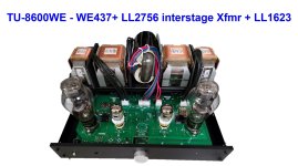
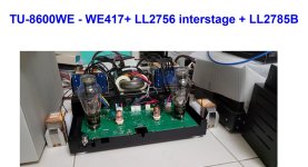
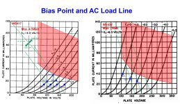
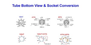
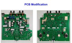
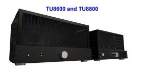
TU-8600 mod WE417/437-interstage Xfmr LL2756-300B-LL1623/LL2785B

I planed to build up a tube amplifier with all WE tubes long times ago and bought WE300B, WE417, WE437, WE274A/B for over 10 years,
but I never made up my mind which 300B architecture to go.
At end of 2021, TU-8600 with LL2785B cured my decidophobia.I bought one TU-8600R and ordered a pair of LL2785Bs from Taiwan dealer THL.
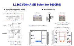
I could not wait to enjoy music played by the vintage 300B, so I tried the transformer LL1623 on hands before LL2785B arrive.
LL1623 sounded excellent with thicker mid range compared to the LL2875B which was a bit more air and more clear sound stage.
I liked both of them and was glad that I could swap based on my moods ! ^_^.
Although TU-8600+Lundahl's transformers were excellent, but my target was an amplifier with all WE tubes.
TU-8600's case is small and outputs of AC power transformer can't support WE274A/B tube rectifier and DC coupling,
so WE417/437- interstage transformer - 300B was the choice.
For the interstage transformer, I used LL2756 and wired it to 1:2 ratio to get 2x voltage gain and accommodate the high bias current of WE437.
I re-wired the input tube sockets for WE417, made a conversion sockets for WE437 and made cathode resistors replaceable for adjusting bias current so that I can try both tubes.
Due to WE437's cathode current can be as high as 40mA, add a buffer transistor with heatsink after the high voltage regulator LR8 for suppling voltage to WE417/WE437 is necessary.
Fortunately, all the 5 transformers can be put into the case by turning the power transformer 90 degree vertically and output transformers and interstage transformers 90 degree horizontally.
I also CNC a black matte acrylic front panel for TU8600 to match my TU8800. (note: TU8800's case was also painted to black to match TU8600)
About the sound, I was happy with my 1959 WE300B and 1982 WE437A, but shocked by the engraved base WE300B and 1952 WE437A brought by my friend for AB test.
Have fun.

Attachments

  • 圖片b1.jpg
    圖片b1.jpg
    264.6 KB · Views: 98
  • 圖片b2.jpg
    圖片b2.jpg
    264.5 KB · Views: 89
  • 圖片b3.jpg
    圖片b3.jpg
    216 KB · Views: 91
  • 圖片b4.jpg
    圖片b4.jpg
    277.9 KB · Views: 84
  • 圖片b5.jpg
    圖片b5.jpg
    102.9 KB · Views: 86
  • 圖片b6.jpg
    圖片b6.jpg
    126.8 KB · Views: 78
  • 圖片b7.jpg
    圖片b7.jpg
    407 KB · Views: 94
  • 圖片b8.jpg
    圖片b8.jpg
    190.7 KB · Views: 90
  • Like
Reactions: CohibaJoe

same sealed box for midrange and woofer?

In converting a two-way sealed system to three way, I want to attach a 4 inch open- back midrange driver to the same baffle that a 12 inch woofer is mounted on. If possible, to cut down on the amount of work in making the conversion, I would like to avoid building a little box for the midrange.

The crossover frequency between the woofer and midrange is going to be 500 Hz. The free air resonance frequency of the midrange is about 60 Hz. So even if I back-load the midrange with a small box, the pass-band for the midrange is going to be well above the resonance frequency of the midrange. But as I plan a first order cross-over, it might be beneficial for the sys. resonance freq. of the midrange to be close to the free air resonance freq.. So that would be another reason not to give the mid its own sealed box.

I haven't read it explicitly stated anywhere, but my assumption is that separating the acoustic outputs of the drivers is maybe necessary because the back wave of the woofer potentially will distort the sound of the midrange if it isn't blocked from acting on the rear of the cone of the midrange.

How about if I give the sealed box a 100% fill (of damping material); do you think that that would prevent the rear wave of the woofer from driving the cone of the midrange?

Hey, this is one of my longer posts,
cT

Technics SP10 Mk2 not spinning

Already posted this in the massive SP10 tread but worried it may not get seen in a 146 page thread and have a customer who uses this professionally losing money on its "down time" so hoping for a quick-ish answer from a specialist on the SP10. If not OK then sorry mods just delete it.

Have a Mk2 in from a customer and its got me pulling my hair out! The service manual is about the most arcane document I've ever seen for a start... but I digress....

It is used almost all day every day apparently and left running continuously. The customer reported that when returning to the TT he found it had stopped rotating and noticed that the PSU was much warmer than normal.

When delivered to me and set up well lo and behold it worked perfectly... for about 10 mins then it simply stopped.
Seems to be that worst of all faults, probably an intermittent IC or transistor which is neither S/C or O/C.

Following the fault finding chart got me nowhere. Everything checks out as it should when going through the "platter fails to start" flow chart. This flow chart is incredibly misleading as many of the voltages it asks you to check in fact vary widely depending on platter position! It says A1 to 3 should be 23V DC but in fact they are the drives to the motor and go from around say 3V to 28V ish as the platter completes a rotation pushed by hand. The PSU, drive heatsink and even motor all get warm as they are sitting there with a load on them but "stalled". Yes the brake is not stuck on and works as it should!

If you manually push the platter it seems "to want to go" and sometimes will rotate a few turns on its own.

The PSU is fine and recently recapped and all voltages correct.

I presume there should be a permanent frequency presented to the phase comparator/control board for comparison with the FG signal but there is nothing but DC levels on its edge connector. The manual seems designed to protect Matshusitas IP rather than aid fault finding and I cannot find any reference to eg "the reference signal from the oscillator divider board enters the control board on pin E11..."

Also, what is the input to the drive board? It's not clear if there should be an AC signal which is the drive to the motor after being split into 3 phases or or if the drive board takes a DC level and speed is proportional to this?
"a2" looks like an input but the fault flow chart says this should simply be 22V DC, which it is. Is there a simple way of feeding a signal from a signal generator to the drive board as a mock drive signal just to see if it eliminates this board? Or alternatively a point which can be either grounded or have a specific DC level applied to do the same thing?

I've spent about 7 hours on it so far with no results other than everything checked so far looking fine other than a suspicion that I should be seeing waveforms on the PLL/control board but there are non. It doesn't help that the manual shows loads of waveforms which should be there WHEN THE PLATTER IS REVOLVING but as it's a closed loop system it's a fault finding nightmare! I repair hi fi for a living but it's decades since I last took on a DD TT and I took a chance in accepting the job that it would likely be something obvious like a faulty PSU or S/C output transistor etc but it was not to be and in fact it seems to have one of those faults from hell.... can't win 'em all eh...

Edit: The crystal oscillator works fine, a square wave which changes in frequency when 33, 45, 78 are selected is present at "P2". The 50KHz oscillator on the drive board is working and all the "feedback phases" from the "sensing/commutating coils" give a DC signal proportional to platter position as they should via their respective rectifiers etc. It just sits there pulling current but not commutating and very much "still life".

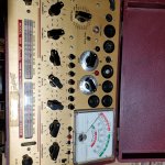
My new to me Hickok 800

Continuing on this steep learning curve of hobby electronics , I found myself in need of a good tube tester and found a Hickok 800 at a reasonable price . Asked the seller if he would give me a demonstration of how it worked and the sneak tested a tube in front of me telling and showing me how the tube was clearly passing better then new by the needle being in the green zone . Sadly he was giving me a snow job because with the English wheel in that position should have been reading the micromhos scale not the red green scale . The meter was clearly showing me the tube was failing when I got it home in both testing modes . Being that this was a known good tube I now knew the meter was way off , like way way off . When selling his story was it's just a little lower then my other Hickok meter . And now his story is ,I told you it was 400-600 micromhos low , and you just need to twist some pots to calibrate it and get it working LOL .. The machine does not even have trimming pots that I could see . But the joke is on him because all it needed was for me to spray all the pots with Deoxit . I figured before doing anything too drastic I should cover the basics . Anyway I have seen many posts of guys having the same problem and my advise would be to clean the pots before doing anything to this old meter . In the end cleaning the pots raised my reading by 900 micromhos . So now the tubes that were failing are passing with flying colors and the ones that were marginal are actually exceptional tubes . I don't know why some guys feel the need to do thing like this just to make a few bucks , I told him I was just learning and asked for his guidance , He was clearly advanced in his knowledge and used that knowledge to try and take advantage of a beginner , He could have told me the truth and I still would have purchased it . Question now that I have the meter working well I see the meter has to ports for testing NPN & PNP transistors does anyone know what the leads look like that went with this machine , or did you just push transistors in the port . Not that I would use them a whole lot but like my meters to be complete . thanks Roger

Attachments

  • 20240819_092435.jpg
    20240819_092435.jpg
    950.7 KB · Views: 103

Newbie Here To Learn

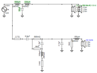
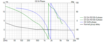
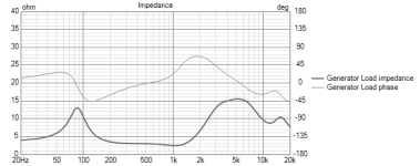
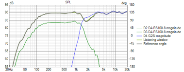
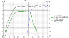
Hello everyone! Brand new to the scene and excited to dive in. I've spent the last 2 months reading and re-reading Intro to Basic Electronics, Speaker Building 201 & The LDC 8th edition volumes I & II. I have also been learning Vituix CAD and playing with Xmachina. My next steps will be getting testing equipment. Any recommendations on a cost effective setup would be great! I have a good selection of old speakers from brands of varying quality that I plan on disassembling to use the drivers for experimentation. I have been playing with the half space responses of 2 MTM configurations. Both use the Dayton RS100-8 mid bass and I have experimented with the Morel CAT 308 dome and Aurum Cantus G2Si ribbon tweeters. After completing a few test builds with the drivers I currently have, these will most likely be my first real shot at a quality loudspeakers. I am currently using Cambridge Soundworks and Triad MTM speakers scattered around my house that I can use for reference. I understand that the half space responses are not indicative of what I will be working with in reality. I am going play with the simulated diffraction in Vituix now as practice but I have some concerns with my current designs that I could use some direction on. For both alignments I have good frequency response and the phase and group delay seem appropriate. My concern lies with the impedance. The first alignment using the G2Si tweeter shown below dips to 2.8 Ohm and hangs at 3 Ohm from 200-1200 Hz low point. The second alignment using Cat 308 in my next post runs 3 Ohm from basically 200-2000 Hz. The second alignment is more consistent and has far less circuitry but I would like to try and build both. In both configurations the problem seems to stem from the large parallel capacitor in the low pass section. However adjusting this drastically effects FR. I welcome any feedback on these designs! My questions are as follows.

Are these impedances going to cause problems for a lower end amplifier?

Is there an easy work around to raise the total impedance that wont affect efficiency to horribly?

How does the load phase affect the impedance? The peaks in phase correlate to higher impedance levels, when the impedance is at its lowest the phase is close to 0. This means it is mostly resistive correct? Does this present less of an issue for the amp?

How does the acoustic phase look? Configuration 1 is 90 degrees out of phase in the low pass stop band. Is this ok?

If I invert the tweeter I get a 6 dB drop at the crossover. Is that steep enough?

Does any of this matter as it uses half space responses not real world measurements?

Thank you all in advance! So glad there is a place where I can have access to the wealth of knowledge you all have to offer. I attached the Vituix project file as well as pictures of all the relevant graphs. Alignment 1 is crossover variant 1. and 2 is 2

Attachments

  • TEST 2  XO-schematic.png
    TEST 2 XO-schematic.png
    6.7 KB · Views: 37
  • TEST 2 GD+Phase.png
    TEST 2 GD+Phase.png
    8.9 KB · Views: 34
  • TEST 2 Impedance.png
    TEST 2 Impedance.png
    7 KB · Views: 35
  • TEST 2 INVERTED SPL.png
    TEST 2 INVERTED SPL.png
    10 KB · Views: 31
  • TEST 2 SPL.png
    TEST 2 SPL.png
    12.3 KB · Views: 56

Building a Choke-input PS for the RH84 Amplifier - Component Layout

Greetings, friends. I've been interested in building an amp choke-input power supply for some time. The pros and cons are a bit nebulous, the components required seem to be subject to mythical requirements (what's a swinging choke?), and neither Merlin nor Morgan devote much ink to them. So I come to you.

The RH84 webpage offers 2 designs for a power supply: the first, a traditional CLC

RH84 - rev2 CLC.png


straightforward. He's nice enough to include voltage ranges for 5R4 and 5AR4 rectifiers.

It's the second PS design that intrigues me, a Choke-input LCLC supply:

RH84 - rev2 LCLC.png


And here's where I'm seeking the wisdom. The image above lists the first criteria for the first Choke: 10H, 100mA, Enclosed or Potted, something like the Hammond 193G. The second choke can be a cheaper, open bracket Hammond 158M or 159P, ok.

In the text below the image, the author states that, "Particular attention should be given to the choice of the input choke – it will be prone to vibrations, and thus needs to be a potted or enclosed unit, as stiff as possible. Care should be given as well to the positioning of this choke, since it will have an important magnetic field due to the difficult task."

What is the ideal position for this Choke? Many tube amplifiers I've seen employ a layout where the power supply components occupy one end of the chassis, keeping any AC voltages as far from the audio components as possible:

translayout1a.png


sometimes the Choke is turned 90 to the PT:

translayout2A.png


would either of these layouts prove suitable for a Choke-input power supply? Is it worth the extra $$ in components to arrive at the same b+ ?

advice, wisdom welcome.

thanks!

w

Tweeter question

I have a 2 questions about my tweeters.
Earlier this week I commenced a speaker crossover project to redo the components and wiring in my speakers that I constructed in 2018.
When I examined the tweeter crossover I found that the shunt resistor had burned up and fused itself. The resistor was a 5W Mills 10R. The tweeter is a Hiquphon OW-1. The tweeter appears to be just fine, or at least it looks undamaged. But when I test across the terminals on the back of the disconnected tweeter, there is no reading on the DMM.
I am thinking that this tweeter is not good and not now working.
So I checked the tweeter on the other speaker, that I have yet to disassemble. When I test the tweeter while connected, I get a reading of 4R, but not the 10R of the shunt resistor. And when I disconnect the tweeter, I get a reading showing a small resistance, but not 0R. So I am thinking this tweeter may not be blown, but maybe not quite right.

Question 1 - Are my tweeters blown?
Question 2 - Why would the shunt resistor get burned up and fused?

It is easy to buy a new pair of tweeters. But I need to have an idea of how to prevent, if possible, a repeat of this situation with the burned shunt resistor and apparently blown tweeter.

Thanks in advance for any ideas and advise.

Monacor SP-50x

Hello gals and guys,

I'd like to know what you'd do with a bunch of Monacor SP-50x. I don't mean the new version with the dreaded plasic-chrome whizzer but I mean with the old ones, which got the bigger whizzer paper cone. I know of the Klang+Ton Cheap Trick CT193 (of the German magazine Klang+Ton) which used the SPH-60X which I've built several times and sounds really great, very high dynamics and for the size of the FR, unrivaled bass performance, the horn reflex performs amazingly. Since I've already built so many of them (the 4 Ohm version performs even better!) I'd like to hear what you think about the SP-50X and how you'd like to use them. They've got a good spl (just a tad below 90dB/2,83V), got a very nice, even and borad midrange and the highs are nice, better than the SPH-60X but good dome tweeters will perform better on the top end. The SP-50X sound very smooth and realistic in the hights, unlike the actual model.

What would you do with these FR 13cm drivers?

Use them as sat for 10" or 12" subs?

Can you imagine them as double mids (MTM) in a PA speaker?

I've heard them in a 8x and 4x configuration for two disco side rooms, but I don't have enough of them and the chrome plastic ones sound so horrible, it's not even funny anymore.

I'm not fixed on PA, what would you use them for?

Triode comparison - EL34, 6L6, 5881, KT88, 6550 etc

I'm looking for some sonic comparisons between these much-used octal outputs wired in triode. Plus any fairly close octal equivalents like KT66, KT77, KT120, KT150 etc. Not including the lower power octals like the 6V6 family which we know to be good - just those with dissipation of 18W or over in triode.

Which of these have you used, and which would you recommend on the basis of sound quality? Thanks.

Nakamichi PA 7AE - repair; never came across an issue like this before

Greetings and Salutations,

I got myself a PA 7E. Unfortunately, the a** who sold it to me thought it was a good idea to damage it in such a way that the new owner would just throw it away.

Long story short, I repaired the right side, but the left side is still tripping the protection circuit. It turns out that the output has an offset which triggers the protection circuit, and the pots don't change anything when turned either way.

Now, this is what makes it really strange (at least for me): Connecting the left side to my lab power supply (+-68V), that damaged amp works flawlessly. Unfortunately, that is the max I can get out of my supply. I know the datasheet says it should be +-60V, but the supply of my and other people's PA 7E seems to be running at +-80V. Anyways, I have also connected the (bad) amp to the other power supply side where the other amp works, and it does the same over there: the output has an offset, and the pots don’t change anything.

What could be causing this kind of behavior, and how could you repair something like this? Could a 12V difference trigger bad diodes and transistors and revert their behavior when under-volting? I mean, these are old semiconductors—is that something rather uncommon? I have come across half-bad semiconductors, but never ones that would behave differently with a 10% voltage increase/decrease.


Thanks in advance and Best Regards from Germany

Attachments

Mini 2-Way with Peerless

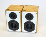
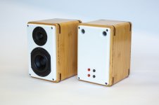
We built a pair of mini speakers for a young student at university.

The idea came from here :
https://projectgallery.parts-express.com/speaker-projects/sls-85/
https://audioxpress.com/article/Test-Bench-Tymphany-Peerless-SLS-85S25CP-04-04-3-5-Woofer

But with a different enclosure made from bamboo ply's from IKEA, with front and rear from white Corian.

The drivers are available at Digikey, which makes ordering real easy.


Patrick

.

Attachments

  • 800px-9412.jpg
    800px-9412.jpg
    71.7 KB · Views: 179
  • 800px-9408.jpg
    800px-9408.jpg
    47.8 KB · Views: 177

Capacitors in CCSs

Hello,

today I received my copy of Merlin Blencowe's book Designing High Fidelity Tube preamps. I opened it about in the middle and fell into chapter 6.1.3: Cascode BJT Current Source. Merlin writes that a CCS's dynamic impedance can be increased dramatically by paralleling the reference LED's or zeners with a capacitor. But it takes absurd high capacitance values to keep the impedance high in the LF region also. Now there are gold capacitors with values in the F(arad) region. Were they suitable for this purpose if the total reference voltage is kept well beneath their voltage rating?

Best regards!

JBL 2226 Cone Parameters

So I am not sure if I put this in the right forum but it seems to be the best spot.

I am reconing 2 of my JBL 2226H drivers which had been previously reconed badly (not by me).

I purchased a set of cones from ebay a while back (2 years ago or so) to do some checking on cone weight but never got around to it until now (to many projects). The cones came from one of the reconing guys well known online that has a store on ebay but unfortunately I cannot remember who. Nice cones look the part and matches everything visually as well as in their physical dimensions (except weight). When I weigh this cone its 48.7 grams.

The cone that I took off the driver yesterday was an MW marked cone that weighs 56 grams. Other then weight the two cones (ebay vs MW) look identical.

I do not have any original JBL 2226 cones other then the ones I have on another pair of JBL 2226H drivers I'm using in a set of Clone 4343's I built a year ago. When I look those cones up and down they too look like they would come in on the heavy side if I could weigh them.

So my question is:

Does anyone know the weight of an original JBL 2226 cone or do you have one that you could weigh?

Thx in advance for all your help.

How to build a Digital input ( create DAC ) on a Technics SL-P999 CD Player

hello
someone already did this job on this forum with philips CD4000

so I would like to make my high-end CD player Technics model: SL-P999 work as a DAC.
so I would like to install an optical input.
because the sound of this cd player is phenomenally fantastic.
it says on it that it should be 20 Bits, now I don't know how much that is. I know, I know electronics, but not too much.. I know how to solder wires and work with a multimeter. but I'm a complete zero in this project. haha
i know i need a board most likely SPDIF to I2S.
would it be possible to connect this thing to my technics cd player.

question about the Oddwatt 6BQ5

I have been looking for a good 6BQ5 push-pull project. I found the followng: OddWatt - ECC802S SRPP / EL84 (6BQ5) Push-Pull Tube Amp

here: https://diyaudioprojects.com/Tubes/EL84-Push-Pull/

My question regards the B+ on the various projects.. In the original thread, this project is referenced:

Compact Hi-Fi Power Amplifier by Melvin Leibowitz​

found here: https://diyaudioprojects.com/Technical/Papers/Compact-Hi-Fi-Power-Amplifier/

Many here are likely familiar wth these projects.

Here is my question. In the referenced Leibowitz project the B+ is 260v with 250v applied to the plates. In the 'final' version of this amp, updated 9 October 2012, the B+ is only 210v. Why the drop n voltage? Seems like a lot.


Roger

For Sale 6 pieces NOS 2SJ74GR

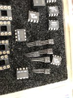
New/unused NOS 2SJ74GR. Since I got fed up with receiving relabelled 2SK170GR I offer these 6 pieces for sale. Also I noticed the future is definitely the other way.

Absolutely original from decades ago and always kept ESD safe which I can recommend to anyone. Make me an offer that is OK so I can buy those JFET OPA828’s.

EU only!!!!

Yes there are OPA604AP, OPA603AP, OP90 and OPA637BP pairs on the picture. Also for sale.

Attachments

  • image.jpg
    image.jpg
    551.7 KB · Views: 105

Any good resources on 2.5-way cabinet design?

Hi,

About to finally start tinkering and I like the idea of a compact 2.5-way...CamillaDSP (RPi5 & HiFiBerry DAC8x) to create the active crossover and 6 channels of amplification, the parts per speaker:

2 x Wavcor WF168WA02
1 x Vifa NE25VTS-04 tweeter)
1 x Dayton Audio DS270-PR

As compact a cabinet as possible, I don't want floor-standers or anything too bulky.

I can't find much info on how the enclosure would differ, or whether it needs to differ at all, layman's terms would be great!

Thanks
Richard

Anyone familiar with removing/replacing volume knob on Sony STR-DH190 - DH590 line of receivers?

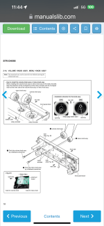
So I picked up this DH190 receiver for practically nothing. I’ve only tested by using its bluetooth capability with my iPhone and it worked great! Anyway, I was cleaning it up and discovered unlike every other knob on a receiver I’ve ever pulled off to clean (the receiver was filthy), you’re supposed to use a screwdriver stuck through a hole from inside the chassis to release it. I’ve seen knobs with set screws but nothing like this. Anyway, not knowing any better, I forced the knob off by pulling it and the white ring separated from the black knob itself. So I found the service manual for the similar DH590 model they showed how I should have removed the knob. Problem is putting it back on. Can someone look at this pic from the manual and explain what they’re trying to get across from the “ok” and “ng” drawing showing the orientation of the knob? And is there a certain way this white inner ring is supposed to fit on the knob? And what purpose does it serve? Thanks!

Attachments

  • IMG_3896.png
    IMG_3896.png
    246.7 KB · Views: 142

Distortion Measurements of a MOSFET Relay for Loudspeaker Protection

In recent years, more and more hi-end audio manufacturers are turning to MOSFET relays for loudspeaker protection, most notable of them Accuphase.
Unless used in the shunt mode to short circuit the amplifier output, a loudspeaker relay is in the signal path.
If the contact resistance of the relay is not low, consistently constant over lifetime, and sufficiently linear,
it will be a source of added distortion between speaker and amplifier.
This is particularly the case for low-level signals.

While MOSFET relays do not suffer from those problems with a mechanical contact, the linearity of its “contact” resistance has not been reported in public.
Most measurements seen to date are those in conjunction with a resistive load.
If the distortion spectrum with or without the relay are seen to be identical, then the relay is declared distortion “free”.
This of course depends on the distortion of the base amp in the first place, with examples up to -90dB THD or higher at 1W 1kHz into 8 ohm.
The true performance of the relay is then hidden behind the base amp’s distortions.
I was told in private that this was actually how a well-known hi-end manufacturer measured their own design.

Not entirely satisfied with this, we set ourselves the task to try to measure the distortion of the relay itself directly.
As you can see in the article, we have successfully completed the task, and the DUT itself has a distortion below -80dB even at a current of 1Arms,
corresponds to 8W into 8Ohm.

PS Most sincere thanks to Jan Didden for carrying out all the measurements.


Patrick

.

Attachments

  • Like
Reactions: Vincent77

Andrea Mori - TWTMC - C incl. Laptech Crystal - ideal for Shigaclone

As I am slimming out my DIY projects backlog due to the lack of time building all the stuff lying around I will post many undone projects and PCBs I collected over time.

Starting with Andrea mori great "The well tempered master clock" (see here).

Only offered as a package. Ideally suitable for a Shigaclone upgrade (was intended to use for my MK II but I was to lazy to replace the installed Tentlabs crystal).

Set contains:
  • TWTMC-C Main board
  • one daughter board
  • Laptech crystal fundamental AT-cut 16,9344 MHz

Everything was safely stored in a dry place in the envelope Andrea sent me the stuff. Don't remember
exactly what I paid for, should have been about 60$.

SOLD

Best regards,

Fabian
tempImagek2wISO.gif

For Sale Shigaclone MK1 by Vicol - finished and tested

Cheers my DIY friends,

continuing to go through my, seems endless, boxes of DIY stuff I found my first iteration of Shigaclone I built back then in 2014. This version never actually got an enclosure and was just built on a wood bracket until I built my MK2. It is completely hand soldered with fine selection of components (Vishay MELF resistors). It is a "basic" setup, so no enhanced components (see enhancement options) like Tentlabs clock / Andrea_mori clock (see my other sales thread, I have a perfect match for offer), Vishay Naked Z-foil resistors on SPDIF Out and so on. Still it already sounds great. It comes as a full set without cables and remote control. Just need to add your own toroid, pick it in a case (or on a wooden board) and a DAC and be happy listening.

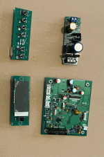
Set consists of:
  • Shigaclone MK1 Board by Vicol, completely soldered and tested
  • PSU by Vicol
  • Display board (Display even has the original protective film on it)
  • Button board
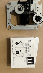
  • Sanyo Transport original SF-P101N 16 pin
  • original Sanyo Laser Replacement (in case you want to try the Laser mod and **** happens)

SOLD


tempImage4Zq3UO.giftempImagempZP0k.giftempImage9huck1.giftempImagejks9n7.giftempImageiD8pD0.giftempImageZFCeJ1.giftempImagezfzTrI.giftempImageeS8KcB.giftempImageLBYVBa.giftempImageRpbp0y.gif

Entry level signals generator

Hi i would start with some measurements on line level buffer and preamp
So the max Vout from the units under test would be 3-4 Volts ( i have two low noise sound cards to try on the receiving end just to start)
But i would like to buy a standalone signals generator
I wonder which would be the price for something decent (i.e. low THD)
I see some units but i cannot understand their real performance

https://www.amazon.it/YIWENG-Generatore-arbitrarie-campionamento-memorizzazione/dp/B0CP58XNVG/ref=sr_1_57?crid=30DKIZFY2IUG2&dib=eyJ2IjoiMSJ9.Yz-ADEB7520kupg1GfSit1pm0QbliAuqk1XafbbUKOAVN8-gqXbMerZ8MiUVA7NZ_Jc5Z3SugzYtCN-G1zyoGFiK89UDOuuZbfCZtGKxw52vLy2XYb_cv1gACfePQAdr5VyOngxqZvjZlwqx9M4Fdwi63VqLNLkEo2XrY5KhEBSCihnHdyLOkJ4RIUHfeozRND_ZNmIB6etexmZ1KWLf1BkmWmdCKnlkGzpkpa3lM9NjdNRzpkLuF4l6nWA1gWxG5UsedpskOdz3XrmZoSq16SfWOkLmAJVig0hHrg46l5Y.mAQ7ZClWtKKu-uUk5nHDhDpiJ8RIDQwsmC4nRccuElM&dib_tag=se&keywords=generatore+di+segnali&qid=1719653548&refinements=p_36:6800-&sprefix=generatore+di+se,aps,257&sr=8-57&th=1

https://www.amazon.it/Generatore-Contatore-Controllo-Sinequenza-Ac100-240V/dp/B0CSDZ3VT8/ref=sr_1_92?crid=30DKIZFY2IUG2&dib=eyJ2IjoiMSJ9.eb34Ik6wXn-CoZU6FrlBGS-X1U2l_ecDWcGBaMnreFP-Zc7B4KXSewv1zZWEpcEsYpogH4yM8VAS2VFWymXuRXdYbOTf1af1xGG3IAbJ-Aa9ueyPI_f2wlTjxDak4BnFdZIHcmlFTm-fhUnK1JY-i4X7nq5Am1C1kueIOGYMpv0VV4ZANDpjKPA5SsNG4a_WfOxCuszLq15QdG6-hz5phJ7ifggL_bvxHSiK7cf8miRyMsdRLKFsphoXrG5chshcouM5HnJaCmM8BJjdINyBH7XgZd1MeRZD4-VqjnT0VB4.rvEk96AKTC2mT27RApA0b1SMlyJJoz_xbGAPxgLrmGY&dib_tag=se&keywords=generatore+di+segnali&qid=1719653615&refinements=p_36:6800-&sprefix=generatore+di+se,aps,257&sr=8-92

Would these cheap units clearly a better option than a soundcard plus SW ? i am mostly interested in sine and square waves
Thank you very much to all

NAD 1600 Re-Cap

Hi All,

1st time poster!

I'm running an old NAD 1600 and 2 NAD 2600's...sometimes bridged sometimes not.
I replaced the speaker relays in both 2600's a few months ago and now they work great!
The 1600 has now started to have the left channel louder than the right. I have confirmed this buy running each 2600 separately with a different pre-amp.

I haven't opened it up yet to take a look but am wondering, could it be something as simple as bad solder joints on the pre-in rca connectors?
or is it just time for a re-cap?

Any suggestions of caps if thats the case? I did find this kit from the UK
https://www.audio-high-store.com/product/nad-1600-upgrade-kit-audio-capacitors/

Any suggestions are greatly appreciated!
Foo

For Sale Sanken 2SA1294 & 2SC3263

I have 100+ pairs of these (NOS).

20240812_111523~2.jpg

SOLD!!

I guarantee that these are genuine Sanken. Feel free to test them any way you like (or even crack them open to check the insides). If they turn out not to be genuine or if you have any doubts about their authenticity, you can send them back to me (I’ll cover all the return costs), and you’ll get a full refund.
You can mention this in PayPal when making the purchase.

PM me if interested.

Thanks for looking!

Nakamichi BX300E has a squealing sound?

I have a Nakamichi BX300E on the workshop table, and after completing the service I discovered a faint howling/squealing sound from the drive. The frequency of the sound changes up and down when the pitch knob is turned. The sound seems to be produced by something mechanical - perhaps the flywheel? Has anyone observed a similar phenomenon? And what was the reason?

For Sale Troels Gravesen Faital 3WC-10 all drivers

I have for sale a full set of drivers to build the famous Troels Gravesen Faital 3WC-10 3-way speaker pair.
I bought 2 sets and have another for sale because I only finished one set and don't need the other one. I planned to make a WMTMW version of this but the Gravesen original version is already good enough. I'm very happy with the sound of this speaker.

The following drivers are included:
-2x Scan-Speak D2608/913000 = Peerless HDS DT26/08 https://www.lautsprecherkauf.com/SCANSPEAK-D2608-913000.html
-> These are used, barely broken in. Terminals are soldered.
-2x Faital Pro 6RS140-8 http://www.troelsgravesen.dk/Faital-3WC-10/6RS140-8.pdf
-> These are used in test cabinets but not even broken in
-2x Faital Pro 10RS350 http://www.troelsgravesen.dk/Faital-3WC-10/10RS350.pdf
-> These are new in box, never used, in an unopened sealed box.

Jantzen Audio sells this set of drivers for 600 EUR without taxes, means around 750€ with local taxes + shipping.

I'm asking 500 EUR for the set.
Shipping cost will be added. I have the original boxes and can ship to almost anywhere. Ask for shipping quote to your location.

More info here: http://www.troelsgravesen.dk/Faital-3WC-10.htm Here is a summary of that page:
"Dynamic and with a degree of 3-dimensionality rivaling whatever speaker I have ever made, regardless of brand and costs. I know this is big words, but I'll stick my neck out for any comparison on transparency and 3-dimensionality"
"Of any mid-sized 3-way classic, this is the best I've made."

Attached are the photos of the actual drivers.

If you wish, I can measure the drivers using DATS v3 as a proof that they are working as they should.

Attachments

  • IMG_20240901_175052.jpg
    IMG_20240901_175052.jpg
    529 KB · Views: 142
  • IMG_20240901_175103.jpg
    IMG_20240901_175103.jpg
    307.3 KB · Views: 121
  • IMG_20240901_175109.jpg
    IMG_20240901_175109.jpg
    458.1 KB · Views: 122
  • IMG_20240901_175114.jpg
    IMG_20240901_175114.jpg
    414.8 KB · Views: 113
  • IMG_20240901_175123.jpg
    IMG_20240901_175123.jpg
    323.2 KB · Views: 120

FreeDSP AURORA, Jab5, ADAU1452, ADAU1701 - Mess

Hello guys,

I have recently been playing around with a Wondom JAB5 (adau1701 based dsp with 4x"100W" amplifier). This jurney have made me fall deeply in love with sigma studio. It makes working with my fusion amps feel like a joke.. really wished hypex would let us talk to and program the Adau1450 directly.. maan that would be awesome...

However, the Jab5 board and as far as the WWW tells me all other Wondom products have a rediciulesly high noise floor. I have used it to build a pair of pc speakers, and even at moderate listening levels the noise is still audible.
I really really wished there was a decent quality product for maybe double the price that just had the DSP and 8 outputs ready to be connected to amps, but i cant seem to find any.
The best i could find was the Ali/ebay baords discussed in this thread:
https://www.diyaudio.com/community/threads/low-cost-adau1452-china-board.309680/page-24#post-7781475
But having read that thread from start to end, i dont feel thats worth the hassel, simply to bad quality products...
Im leaning more and more towards the official AD eval board:
https://www.digikey.dk/da/products/detail/analog-devices-inc/EVAL-ADAU1452REVBZ/9809249
But the price of that board is almost the same as a full Fusion amp...

Is there really nothing in between china trash and top of the line AD board?

FreeDSP Aurora cauhgt my eye. However, i have no experience in pcb manufacturing via PCB-way and so on so it seems like a daunting process, and i have no clue what the final cost would be...

Has anyone here built the Aurora DSP within the last couple of years?
Is it still worth the effort?
Is it cheaper or more expensive than the AD eval board?
Can it be partially build to only have the DSP functionality without the usb stuff to save cost?

Really hoping for some feedback from someon with FreeDSP experience... Thanks in advance!!

TDA1541A test board issue - DEM oscillator not working

So I built a test board to try and measure some ideas. I added the components for the famous Grundig DEM clocking and it was working fine. Then I though I check it against the data sheet single capacitor solution, I connected a 680 pF foil capacitor between pin 16 and 17. It does not work. There is some low level, high frequency oscillation, but definitely not the well known waveform that should be there. I checked the capacitor, potential solder bridges, continuity, everything looks in order. What did I miss? The chip is in a socket.

GerardV?

Maybe I'm just stupid, but I can't figure out how to "contact GerardV", as directed in the Member Blog area. There's no "start a discussion" option below his information box to contact him by. ??

I'm thinking about starting a blog, about a DIY project that others might be interested in, but if I can't do a blog then it might just have to be a forum thread.

Thanks
Bill

Audiosource Amp 310

I've had an audiosource amp 310 faithfully serving me for over 9 years. It recently started behaving erratically, and now takes 20 or 30 minutes to eventually come on after being powered up. When but when it does come on, the amp functions just fine. The behavior is consistent regardless of the auto-on settings on the amp. There is no evidence of burnt components or leaking capacitors, so I am guessing there is a bad relay somewhere inside.

I have reached out to audiosource and googled high and low to find any information on this amplifier. There are several posts in this forum related to the amp 200/300 but from looking at the drawings, they are very different from the 210/310.

If anyone has any documentation on the 210/310 or advice generally, I would appreciate you sharing it.

Many thanks!
Brandon

B2 AUDIO M15R the raven! Output Mosfets

Hi guys, a B2 AUDIO M15R amplifier with a burned audio section is about to arrive at my lab.

Looking at the board online, it seems to be a classic Korean one with 1 X IR2184 + 2 X TC4452 buffer and if memory serves, it should use FDA20N50 as output mosfet.

If so, I saw that the output mosfet is not very easy to find at the moment.

Has anyone tried any reliable substitutes?
Did you have to make any changes?
thank you all

Dead KEF X300A - what to do with them?

Hey there,

Kind of off-topic, but I need your opinion. I've got a pair of KEF X300A that aren't working any more. Apparently there is an issue with the power board. According to some comments on the internet, it's an expensive replacement that's probably not worth it.

I'm now wondering what I could do with them, I'm neither an audio nor electronics nerd (besides basic stuff). Does it make sense/is it possible to use them as passive speakers somehow?

I'm thinking about replacing them and wonder with what. I've used them as Desktop speakers, the sound is excellent. But I'm not sure if I want to use active speakers any more, don't want to throw them away again if they break.

Anyone got an idea?
Thanks a lot!

Installing the new 2023 version of LTspice

********** Installing the new 2023 version of LTspice **********
This is a companion thread to:

Installing and using LTspice IV (now including LTXVII). From beginner to advanced.

********************************************************************************************************************

LTspice 17.1 is a significant upgrade to LTspice XVII, including new features and numerous performance and stability enhancements:
  • Transient Frequency Domain Analysis. LTspice 17.1 includes a new frequency response analyzer component and associate .fra spice directive.
  • Frequency domain analysis has been reduced to a single component and directive, greatly simplifying the generation of Bode plots for non-linear circuits, including switched mode power supplies
  • Both loop gain and output impedance are supported by this feature
  • Improved Installation. LTspice library files are stored in users’ %LOCALAPPDATA% directories, instead of My Documents
  • Waveform Viewer. Faster plotting speed for large datasets
  • Keyboard Shortcuts. Keyboard shortcuts can be saved to and loaded from text files
  • Schematic Capture. Numerous schematic editor bugs have been eradicated
  • Simulator Operation
  • Fixed a number of convergence problems
  • Updated initial conditions behavior and documentation to match behavior
  • Reduced multi-threaded CPU loading

We, the LTspice development team we are very interested over your feedback.


***********************************************************************************************************************

This thread is very much a work in progress and is not intended to be a definitive tutorial.

Take away points at a glance:

The locations and file paths of the directories used by LT are as follows:

%userprofile%\AppData\Local\LTspice
(this is user profile location of the 'examples' and 'lib' folders that in LTXVII were located in 'Documents')

%userprofile%\AppData\Local\Programs\ADI\LTspice
(this is the location of the program files that in LTXVII were located in C:\ program files)

%userprofile%\AppData\Local\Temp
(this is a temp folder. Running a .asc from a file located in the above link (program files) will create a zipped temp folder for that particular sim )

The latest incarnation of LTspice brings some fundamental changes to the way LT is installed and used. The big difference is in the locations used to store the program files and in its handling of temporary files.

If you are installing alongside an existing installation then only certain sections of what follows will be applicable.

Also note that Analog Devices have said that the new version coexists happily with the older version. I made the personal decision to move exclusively to the latest version because I felt that two systems that are fundamentally different in their operation and in their handling of files was going to be problematic although YMMV on that viewpoint.

Having decided to make the switch now to exclusively use the latest version I devised this procedure. What follows relates to Windows and was devised to give a clean install of the latest version.

Warning... make sure to back up ALL of your personal LT files and models wherever they may be located. If you have any residing in the protected program files area then back these up BEFORE uninstalling LTXVII

1/ Download the new version of LT direct from the analog.com site. Do not install at this point.

https://www.analog.com/en/design-center/design-tools-and-calculators/ltspice-simulator.html

2/ Uninstall the existing installation of LTXVII via Windows 'Control Panel' by going to 'Programs and Features' and clicking on LTXVII. Follow the on screen instructions. Also
delete or unpin any shortcuts you may have on the taskbar, start menu and desktop. The program deletion will not affect any of the existing LT files in your user Documents Folder. This includes the 'Example' and Lib' folders.

01_Uninstall.jpg


3/ Manually delete the 'Examples' folder from the Documents location of LTXVII

4/ Manually delete the 'Lib' folder from the Documents location of LTXVII but first check you have copies of all your own models you may have created.

5/ Copy the LTXVII folder in Documents to a secure location if needed for future reference. In my case this contains all my own LT files of information, sims etc.

6/ Delete the LTXVII folder in Documents and restart the PC. Remember to make sure you have backups of personal files located here.

7/ Warning. Do this next procedure at your own risk. Modifying the registry can cause system instability if done incorrectly. What I am doing here is deleting all references of LTXVII that have been left behind following the uninstall.

Open 'Regedit' and click 'Edit' and 'Find'. Delete all entries relating to 'LTspice'. Use 'Find Next' to work through the registry. When completed restart the PC. A further check should now reveal no instances of LT remaining.

02_RegEdit1.jpg


03_RegEdit3.jpg


03_RegEdit2.jpg


8/ You can now run the installer for the new version in the normal way. Accept the license agreement and follow the wizard. Installation is very rapid compared to the older version and took under 10 seconds.

9/ You will now have a new desktop icon for LTspice. Hover over the icon and note the file path. I would recommend you create a text file and paste all these file paths to
that as a means of keeping a record of what is where. This is very important because the installation is now in a non indexed location which is a major plus point for
anyone who uses disk imaging. This is because the Windows index file is not normally included in a disk image and it can take a long long time to rebuild following a
restore. Before I started this I had around 38k indexed items. This figure is now around 25k with most of those 'missing' entries being the tiny model files included with LT.

04_Filepath1.jpg


10/ The first thing I noticed opening the new version is that the new version doesn't scale correctly and the text on the top toolbars is not as sharp as it should be.
That may be because of custom setting I use within Windows. To correct this close LTspice and then right click the desktop icon and click 'Show More Options' and
select 'Properties'. Copy the file target file path which for me is:

C:\Users\karls\AppData\Local\Programs\ADI\LTspice\LTspice.exe

and enter that file path in Windows search box to open the location.

Right click the search result and select 'open file location'.

Alter the High DPI setting as shown.

05_DPI.jpg


11/ Reopen LTspice and the text should now be pin sharp. If Windows opens a box asking Did this program work correctly' answer as appropriate. Hopefully a yes.
I would suggest you now familiarise yourself with the main differences in how LT operates and works with files and folders. Remember that target file path from
earlier. If you look at that but this time delete the end part of LTspice.exe you will open the location of the files if you paste it into the Windows search box.

You should see the familiar 'Example' and 'Lib' folders are now located here (see above image). Notice they are now zipped (compressed) folders by default.

13/ At this point I think it useful to create a shortcut to open the location where LT now resides. I placed two Icon Files (.ico) that I created earlier in the new location that LT resides in and
created a shortcut using these icons. One is for the Program Files and one for Temp Files which we will cover later (Step 13 below).

To add the .ico image. Right click the shortcut and select 'Properties' and the 'Change Icon' tab. You need the file path of the icon to paste into the location box.
If the icon symbol does not display when applied to the shortcut then just 'refresh' the desktop.

06_Icons.jpg


The program file shortcut should open to this.

07_Program Files.jpg


12/ I recommend you now run an example such as the 'Audio Amp' found in the new Examples folder. If you are running alongside an existing installation be sure to use the
new folder.

Run the simulation in the normal way and then close LT.

13/ We will now look at a major difference in the new version. Open LT again and click 'Control Panel' (the hammer symbol on the toolbar). Click the 'Operation' tab and
note the filepath for temp files. This is my file path.

C:\Users\karls\AppData\Local\Temp

I would recommend you copy and paste that file path into a new shortcut which will give you easy access to this location.

Close LT again.

14/ Navigate to this new Temp File location and you should see a Zipped folder that was created when you ran the example above. It remains there until you delete it. Each temp
folder contains the three temporary files we are familiar with in the old version.

Run another simulation and another zipped folder is created. So by leaving LT at its default settings we find we have a new zipped folder that is created for each occasion that a simulation is run.
This is something to be aware of this as the space these take up will increase over time.

Keeping tabs on all these is why I recommend creating those two shortcuts to give you easy and instant access to the file locations.

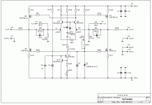
08_Temp Files.jpg
Projects by fanatics, for fanatics
Get answers and advice for everyone wanting to learn the art of audio.
Join the Community
507,520
Members
7,875,268
Messages

Filter

Forum Statistics

Threads
405,638
Messages
7,875,268
Members
507,520
Latest member
jbaudrion