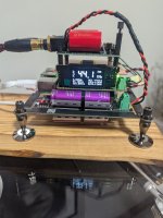
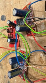
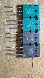
China sealed full range speaker design

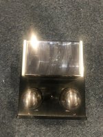
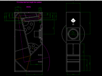
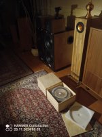
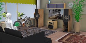
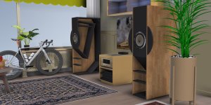
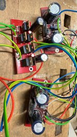
Hi. My 10 years old China Fr drivers which I like a lot ,it's rubbers worn out(last picture )and I bought different but similar drivers 8 ohm instead of 4 ohms. I will use them for my Fast setup. I think I will make 2. Order pllxo and XO frequency will be around 170hz.
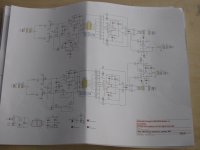
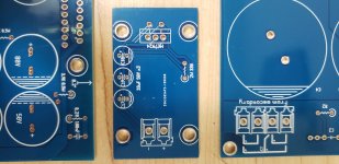
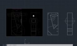
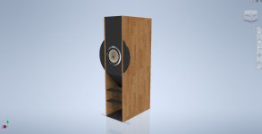
I used BBC ratios for inside dimensions of box. And box sheets will be like first picture.
FS:72hz
Qts:0.57
Vas:4.8lt
İnside dimensions will be 203x165x132mm and box volume about 4.4liters( with effective of poly fiber fill it will be about 5.5 liters)
I think this design will be very good. I already have about 2 meters sheets of 203mm.So it will be easier for me.
What about diffraction of the speakers? Is there a benefit if I round with a milling cutter the left and right sides?( Instead of sharp edges.I know sphere is best for preventing diffraction but Wife started using my IKEA bowls which I bought for my projects and doesn't want to give them to me😂) Best regards

Attachments

  • Screenshot_20241117-142247_Chrome.jpg
    Screenshot_20241117-142247_Chrome.jpg
    123.7 KB · Views: 150
  • Screenshot_20241023-180718_AliExpress.jpg
    Screenshot_20241023-180718_AliExpress.jpg
    197.7 KB · Views: 126
  • IMG-20241116-WA0010.jpeg
    IMG-20241116-WA0010.jpeg
    202.1 KB · Views: 136
  • 17318437510303604525315860100505.jpg
    17318437510303604525315860100505.jpg
    261.8 KB · Views: 134

12" & >=90° Horn : where to cross over?

Hi,


Have a 12" (12PR320). what horn/WG size/type would you choose for such woofer size, please ?

Where would you cross a 12" beaming with a 90° horn ?

I saw new HumbleHomeMadeHifi Mezzo Calapamos now published with a short 90° horn and imho a too much high cut off for that driver... or at least way over its pistonic operation range. https://www.humblehomemadehifi.com/Mezzo-Calpamos.html

I imagine it should be more confortable below 800 hz. Are there horns type that are not 20" wide for such a job, please ? Or at least a horn that would loose itsconstant directivity below but can still match without loadind and/or constant directivity a 12" woofer pattern that low for a seamlessy cut off at ears ?

A good enough 2 ways with a 1.4" compression for home listening level at 3 meters... ?

I lurked on the St260 from the awsome work of Mabatt but seems made for higher cut-off and if I go a 3 way then I would choose more a cone midrange. a bi-radial TAD horn style from the numerous european artisans , But it will push the width in an area that is hard for a living room : a 20" + horn on 37 cm wide column... not sexy !

Any thoughs please , I am not tempted by 60° degree horns as I like a little more "life" from a room in the highs. So i assume a 90° to 110° horn is what (I believe to) need !

Thank you for your inputs.

Power supply troubleshooting

Thread after thread after thread are being hijacked by repetitive questions about minor power supply issues. These discussions often displace the original discussion about the amp or preamp. I asked about this but was met with silence from moderators et al. Let's try this:

Please post power supply troubleshooting questions here. Be sure to include any relevant/needed photos.

Hopefully the members who generously give troubleshooting information will continue to be willing to do it here.

Loudspeakers - looking for a correlation between measurements and listening impressions

Good morning everyone
in a rather interesting video by GR Research Company they talk about a blind comparison test between two speakers with the same frequency response and sound judged different
Admitting the validity of the test I think can we can that the FR alone is not enough to characterize the sound of a speaker ?
The discussion on instrumental analysis protocols unfortunately ended here
The aim of the video was to establish the importance of the xover design and construction mostly Same values different parts different sound
The somewhat banal consideration is that for example speakers showing a very similar FR can have a very different CSD and distortion behaviour
At this point I ask myself but why not make further efforts to understand the dynamic behavior of a speaker ?
instead I see that important and perhaps decisive tests to establish the reproduction quality of a speaker such as CSD and distortion measurements are extremely rare in the various tests
Why? because they are difficult to perform ?
to be honest some datasheets report them But very few unfortunately
i have an idea but i do not want to provoke a storm
i am here to learn
Thank You very much
  • Like
Reactions: Logon

dusting off my 10 year old PA03 PCBs

Hello all,

I built an LM3886 chip amp (BrianGT from memory) around 10 years ago. Thrashed the hell out of it and its still going in the shed.

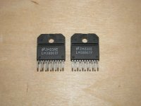
Around 2015 I purchased a couple of the PA03 circuit boards with the intention of making a power amp. I'd hate to throw them in the bin, so I'm on the hunt for a couple LM4780s.

I live in Hobart, Tasmania, Australia.

Regards,
Matt

Service Manual for Rotel RAP 1580

Hello all,

I will greatly appreciate if someone can help me with service manual of the Rotel RAP 1580 MK 1 Receiver.

Several months I struggle getting any info for spare amplification board. I can say for sure that Rotel has terrible service in Europe. It is a total absurd that such a manufacturer/brand with such expensive technique has no good service for spare parts. If I knew that after buying there will be no spare parts and no service manual would not buy it.

P.S. For those interested : I need board: 016X-RAP1580-01-B02
And receive answer that they will send me : 501X-RAP1580-01-C-1-PCB ASSY AMP RAP-1580 LEFT+RIGHT
Still waiting info if it is same board with different name, but will maybe get answer after 1 mount.

Parasound PSP-1500 as a normal Pre ... sensible purchase or not

Hello everyone

I can grab a Parasound PSP-1500 for pretty good money, but I don't know if it's worth buying this device to use as a simple preamp. Since I highly respect John Curl as a developer and this device has an extra button for switching to stereo operation, this makes perfect sense to me. What is your opinion on this, or has anyone had experience with the device in stereo mode???

Replacement for 2N6068

Hello out there...

I need a replacement for a TRIAC 2N6068.
I looked through my lists and drawers and couldn't find a component or any information about a replacement type.
Can anyone help me? It would have to be a fairly common type, since I come from Germany and can't access all types.
It is supposed to do its job on the peak overload board of the Marantz 510M (if anyone needs to specify this).
Have a nice day,
Elektroniklurch

Taramps MD5000.1 DC in Speaker poles

The customer was hooking up this amp and felt the speaker terminal was the B+ Rem Gnd terminals, I’m not seeing any burnt parts but has 12v to the PWM chip but no pre drive from the PIC chip. I’m not getting any five volts from the TI dip regulator but I use a +5 induce voltage to power pic but to avail amp is still dead (no lights at all) could it be the PIC is damage from the wrong connection?
image.jpg

image.jpg

Choosing proper amplifiers for speaker drivers

I have a problem of matching amplifiers and speaker drivers. Attached are 2 styles that I could figure out.
  • System A will assign a stand-alone amplifier, Nakamichi PA302 whose power output is rated 80Wpc @ 4 Ohms, drives the 1.5" midrange dome drivers from ADS L780/2 speakers. And the tweeters of 0.75" from ADS L780/2 as well will be driven by the high-pass channels of Soundstream Reference 405 with 25Wpc @ 4 Ohms power outputs.
  • System B will use the stand-alone Nakamichi PA-302 to drive the tweeters and the high-pass channels of Soundstream Reference 405 will drive the dome midranges.
I'd like to ask for opinions. Which system, A or B, do you prefer and why?

A.png


B.jpg

An A1 descendant - a relentless analysis

Dear colleagues,
In the style of the 20WPA thread, I am posting here an interpretation of the MF-A1 from the large neighboring forum for relentless discussion among experts.

1730469793122.png


Open fire!


The original should be well known, so I will refrain from unnecessary repetition of a well-known circuit.

In the hope of a lasting learning effect, because self-deception helps no one,
kindly
HBt.

Woodworker hobbyist exploring speaker designs

I recently discovered custom open baffle speakers and I’ve been drawn to the idea of making my own speakers. I like the challenge of combining woodworking with electronics to design a speaker that’ll sound great and look stunning.
I’ve learnt a lot from reading posts by Perry Marshall, CTRL, links to websites of Nelson Pass, Linkwitz and others.

SB Acoustic 3″ SB10PGC21-4 Sealed 3rd order Butterworth Plan

Got this little speaker here from discount. Since I need it to be portable for my office, I planned to make it small. (probably around 1.9 ~ 2 liters, sealed with QTC around 1.15~1.16, probably a bit less with additional stuffings). I don't expect bass from this because I planned to get a woofer/subwoofer in the future & probably build 2.1 or WAW system (but that's another topic)

I do need to tame the bump around 140-150 hz after some testing with WinISD. so I will put a capacitor in series for a bit of highpass.

Now at my place, the BP capacitor available here r only 100uf, 220uf, 330uf & 470uf. although not ideal. which one should I buy?

Also SB acoustic did have the formula to decide the capacitor value.....but I only know basic math, tried to search & learn it from google with no avail.

Thank you in advance.

Attachments

  • 20240729_133651.jpg
    20240729_133651.jpg
    292.2 KB · Views: 118
  • image_2024-08-01_144644106.png
    image_2024-08-01_144644106.png
    59.7 KB · Views: 129
  • image_2024-08-01_145103728.png
    image_2024-08-01_145103728.png
    17.9 KB · Views: 109
  • image_2024-08-01_145634154.png
    image_2024-08-01_145634154.png
    21.6 KB · Views: 112

Monoprice Stage Right "All Tube" 15W Guitar Amp Cheap!

I expected this amp to be built like junk, it is not rather it is quite nice and the YouTube reviews are excellent:
Complain about a power cord, come on guys, really?
Login to view embedded media
$238 on Monoprice now, free shipping, some have found coupons for about $200! $279 normally.
https://www.monoprice.com/Product?p_id=611815
$249 on Amazon.

This amp looks very much like the Fender Blues Junior (FBJ) but with some interesting advantages:
EL84 s like the FBJ
Effects loop, none on the FBJ
Switch for 1W practice mode
Adjustable fixed bias design, the Blues Junior has no adjustment and comes with the tubes biased above the max rating
Celestion speaker, cheap one of course
Disadvantages:
Hum, passable but should be better. Edit: Hum is not bad at normal volume settings.
Reverb and effects loop are buffered with TLO72 op amps as is done with most "modern" Fenders
Fuse is internal
No screen grid stoppers resistors on the output tubes
Cheap caps

I bought a very early one used for $125 thinking that it was worth it for the box, chassis reverb tank and speaker.
It is Tweed like in that the controls point up, rather than forward as on the latest production - I believe that the
design is the same.
I'd rebuild it and use it for parts if we don't like it.
This was claimed to have new tubes, a MOD reverb tank and it has an Eminence Legend 12" speaker.
Opened it up and the layout is completely different from the FBJ and not good IMO but should not
be too hard to work on for basics but if any of the surface mount components has to be changed then
it is probably not worth having a shop fix it, and a DIYer will need surface mount skills to do it.
Tubes are JJ s with V1 being a Tung Sol Russian reissue (this was an upgrade by the previous owner)
It has some mods one being a "Neg Feedback" control
Found a schematic not sure if it is early or late, tempted to remove the mods.
Edit: I've decided that it will not be easy to work on so I'll leave the mod in place and let my son try it.
The price was certainly worth it for the case, chassis, speaker, tubes and reverb tank so no loss.
Previous owner told me that the work was done by an amp tech in MA who sold it to him.

If anyone knows of documented mods I'd like to see if those are the ones in this unit, please post a link.

Mark Levinson No 23 volume drop on one channel

Hi guys.
This time a client took a Marc Levinson No. 23 amp to my workshop. It helped him to get it out of the car. Think I injured my back...
He just bought it from an older gentleman and wants me to check it out first.
After powering up, I noticed a difference in output levels. I already downloaded the manuals for this beast.
I think that a recp job is overdue, afer 30+ years,
Any advise on how to proceed?

Help required for wiring two L-pads per crossover (midrange and tweeter)

Hi,

I have my pair of 3-way speakers that I built, and I'd like to add two L-pads to each enclosure (one for the midrange and one for the tweeter).

I tried finding a wiring diagram for this and I did (on another forum), but it confused me because it was combined with crossover components.

Each enclosure has a pre-assembled crossover board, and I have four AT-50H L-pads (two to add to each enclosure - midrange and tweeter).

I know the use of pre-assembled crossover boards and L-pads isn't to everyone's liking, but "it is what it is".

If anyone could provide me with the wiring information / diagram for adding two AT-50H L-pads (one for the midrange and one for the tweeter) to a 3-way speaker with a pre-assembled crossover board, I'd be very grateful.

Looking forward to hearing back 🙂

IJW120R100T1 for audio

Здравствуйте!

Меня очень интересует схема повышения мощности, где в качестве входного каскада используется световой SIT-транзистор.
Такое изобретение позволяет управлять мощным ламповым каскадом с внутренними катодными обмотками.
Это позволяет использовать короткий путь в сочетании с простой реализацией (нет необходимости в двух двойных триодах)
Легко получить более 100 В синусоиды от пика до пика для питания входных сеток мощных пентодов.

Пожалуйста, раскритикуйте симуляцию или дайте совет в указанном направлении.

PS: экономия энергии в этом проекте не важна

.

Attachments

FYI - Devore SEAS A26 kit alternatives

I was looking at the Devore Speaker $$$$$ & the Seas A26 kit, looking at the cost there's got to be alternatives.
$20,975.84 CAD (WHAT !!!)
https://vinylsound.ca/products/devore-fidelity-orangutan-o-96-speakers

$14,000 AUD
https://www.mcleans.info/products/devore-fidelity-orangutan-o-93
DEvore 0/93 Dimensions: 35.5″h x 15″w x 10″d 2.26 cuft or 64 litres

Google Translate
https://translate.google.ca/

YMMV-

GRS-10SFPC-8 Cheap
https://www.parts-express.com/GRS-1...me-Paper-Cone-Woofer-Black-290-912?quantity=1
Compare these two- around 800-1500 hz (up and down-about 10 db)
Seas A26
https://www.madisoundspeakerstore.c...6-10-2-way-kit-pair-based-on-the-classic-a25/

Sound Town STLF-10GA PA/DJ/Bass Guitar (gasp)
(?) 50 oz magnet, vented @71 litres hwd 36x16x10.25 (.75")= 2.53 cuft or 71.6 litres
https://www.soundtown.com/collections/raw-speakers/products/stlf-10ga

Faital 10fe200 4 or 8 ohm HOME HI-FI, PA SPEAKER SYSTEMS & BASS GUITAR CABINETS
https://usspeaker.com/faital pro 10fe200-1.htm
&
Audiopur RT7040 Planar tweeter
https://theaudiocrafts.com/soundtouch-ribbon-tweeter-rbnt1-pair
Russia post #19 crossover 4500 hz
https://forum.vegalab.ru/showthread.php?t=79335
Don HighEnd
https://www.donhighend.de/?page_id=8442

Visaton W250S
https://www.visaton.de/sites/default/files/dd_product/W 250 S_9034_9035_0.pdf
a cheaper Visaton W250
https://www.mouser.ca/datasheet/2/700/W_250-2322621.pdf

Vietnam- Visaton W250S-8 (Operating Fullrange) + Fountek NeoCD3.5H Two Way Speaker
https://linhkienloadai-vn.translate...uto&_x_tr_tl=en&_x_tr_hl=en-US&_x_tr_pto=wapp

old Vifa P25W 70 litres
http://www.sea.vg/vifa/P25WO-00-08.pdf
Vifa SA-130 speaker. 2nd page freq resp graph looks better. (Why couldn't they just use this freq resp. graph)
https://www.stereonet.com/forums/topic/93512-vifa-sa-130-plans-specs/

Any more?

Moderators- move this if necessary. TIA

Attachments

  • 1710822048687.png
    1710822048687.png
    109 KB · Views: 193
  • 1710824123210.png
    1710824123210.png
    64.1 KB · Views: 204

Dealing with the no-load voltage of standby transformers

Hi folks!

I need a low power standby transformer that can produce 12V DC after rectification. It should preferably have a low no-load consumption (P0<0.4W). While searching for such transformers, I realised that the no-load output voltage is significantly higher. This means that when the circuit is in no-load condition, the filter capacitors will charge up to no-load voltage, which is not good. What is the general practice with standby transformers? How can I prevent too much voltage rise without losing the benefit of a standby transformer?

See page 12 of the datasheet for more details. I am looking for part number BV EI 303 8008.
https://www.tme.eu/Document/412ff82a0d9ae839d6b24853d8f56596/Hahn-E.pdf

Thanks in advance
Adam

Hi From Poland ;)

Hello everyone!

This is not my first time here, I have used your advice many times as a passive user, and I would like to thank you very much for it. Now it is time to join the forum and for me, a modest fan of music and saving old vintage audio equipment for my own, amateur needs, it will be a great honor. I spent most of my hobby-time listening to and fixing old German audio equipment from 70' and 80' - for me a golden era of affordable home audio. ReVox, Dual, Blaupunkt, Saba, Wega - designing home audio once an art, today reduced to cost-effective, fast marketing business. I wish everyone best sound, and start to write a specific post this time 😉

All the best,
Mike

New member, I guess.

Hello,

I've had an account hear for the better part of a decade, but have apparently never posted before.

I occasionally build amps, usually using someone else's designs, but occasionally some of my own design (none particularly exotic or interesting). Most of what I do are repairs on vintage gear, nothing too exotic, most of it 70s mid-fi, but also some pro gear.

Looking forward to chatting more.

Thanks!

Sony CDP-D12 CD player motor

I have a couple of these little 1 rack unit players used for playback duties in PA jobs. Both have kaput turntable motors (one tries to draw an amp, the other screams like a ruptured duck). Have the manual with all sorts of part number listings and exploded diagrams, but no mention is made of this little motor. Maybe they expect you to replace the whole damn mech, which is profoundly unobtanium. Any ideas of a source?. Cheers, Mike.
CDmotor.jpg

F5m Build Guide - roboDNA

I intend to use this thread to document my F5m build and serve as a build guide for others.

UPDATE Nov 30 2024:

I have finished my F5m build and it powered up without issue so I'm ready to post a document for anyone who may find it useful.

It's actually not a Guide, but more of a cookbook for my own build. I will leave the official guide to experts who are much more knowledgeable than I am.

The document contains notes I initially made for myself so there could be typos and other errors. I made it available rough instead of waiting for a fully edited copy since it could help new builders as-is.

UPDATE Dec 2 2024: I created a simulation for F5m if anyone wants to take a look:

F5m Simulation

Attachments

Pioneer SA-8800 HF oscillation after rebuild

I rebuilt this amp and am now getting high frequency oscillation at the highest frequency well above the audible range. I have to have my 60MHz scope on the highest frequency setting to see it. It is in both channels but worse on one side. And the unit has to warm up for ~10 or so minutes before the issue starts.
Output transistors were replaced with 2SC5200/compliment. I had to mount the outputs for one channel sideways and use leads to connect them to the board. Not the sort of thing I like to do, but I couldn't find any alternative. The original batwing outputs are obsolete and the transformer plate is in the way of installing the TO-3P straight.
Driver transistors are original. I replaced the input transistors with KSC1845s and 992s.

I also replaced the 10ohm resistors in the stability network (R1/R2 on PS/protect board), as one was damaged. I replaced the associated 0.082uF caps as well.

Any ideas? I'm regretting taking this job on now. These are finnicky circuits and the original outputs are unique.

Attachments

  • 8800.JPG
    8800.JPG
    251.4 KB · Views: 226
  • IMG_5134.JPG
    IMG_5134.JPG
    507.7 KB · Views: 167
  • IMG_5135.JPG
    IMG_5135.JPG
    407.2 KB · Views: 118
  • IMG_5137.JPG
    IMG_5137.JPG
    714.4 KB · Views: 210

  • Poll Poll
OB High power handling midrange 500-2500hz 1st order.

Which midrange would you use in the above scenario?

  • B&C 6MD38

    Votes: 1 16.7%
  • Dayton PS220

    Votes: 0 0.0%
  • Beyma 6G40ND

    Votes: 2 33.3%
  • Eighteen Sound 6nd430

    Votes: 3 50.0%

I already settled on
Sub bass 4x B&C 18tbw100
Bass p audio 15BM500
Tweeter ESS Heil AMT (or possibly nd3st compression driver. I have both and will try both)

But I have trouble settling on a midrange. My choice for 1st order filters is a challenge, especially combined with high SPL. Range will be 400-2000hz or 500-2500hz

Crossovers are DSP

Which of these would you choose and why?

1000003377.jpg

1000003375.jpg

1000003403.jpg
1000003405.jpg

5V/10V LTO Power Supply

Hello,

im playing since a few days with the idea of an Battery Power Supply that can support a possibly wide variety of devices
for me is important that it can provide around 9V for opamp circuits (your usual preamplifier/dacs/line levels i would say) but also 5V is a fairly common voltage, USB for example

Voltages:
So... i compared the voltage ranges (and possibly other pros/cons) and i feel like LTO could be the "perfect" candidate....
(4.4V) 4.6V - 5.2V seems like a perfect 5V USB range
and 9.2 - 10.4 seems like a reasonable 9V replacement
both with the benefit of "pure battery power" ( tho it also seems reasonable to use a low dropout regulator for the 9V range, or diode for a more passive solution)

Batteries:
there are honestly not many solutions LTO wise around.... most attractive size wise are these:
https://hakadibattery.com/products/...y-battery-pack-electric-wheelchair-power-grid
https://hakadibattery.com/products/...w-temperature-battery-cells-25000-cycle-times

as far my search went these two options are pretty much the only cylindrical LTO's

the 18650 have around double ESR and need holders which increases ESR too so i feel like the cap style ones are probably the better option

Design Ideas:
using 4 of the capacitor style hakadi 2500mAh batteries, which can be switched (either by a soldering job or low ESR switching solution) from 2x2 batteries configuration (2 batteries in parrallel and a second double pack in series) or 1x4 series configuration (4 batteries in series)

as these batteries have under 15mOhm ESR the 5V parallel configuration would give around 8mOhm + 8 mOhm, pretty much identical to A123 LiFePo4 batteries, tho im not exactly sure how LiFePo4 compares to LTO directly, i kinda hope for the best here

Charging:
LTO's can be very easly charged via ldo, the cap style ones have a max charge current of 25A and charging with 3A takes around 30-60minutes

preferably i would include a "charge en" input/output, which allows multiple batterie supplys to charge at the same time to optimize "pure power runtime"

since the voltage is either 5 or 10 volt its probably best to use some LDO with a main supply not far from the desired voltage

i saw you can wire something like a LT1083 in constant current mode, but does that mean i need a pregulation LDO for the right voltage max voltage?

Balancing:
preferably simply trough resistors, which power dissapation should i aim for for 3-5A charge current?

Protection:
  • fuse at the output for short circuit/overcurrent protection
  • charging could be triggered by TLV3702 UV threshold

(optional)
- not really nessecary with LTO but i could include a low ESR mosfet + seperate TLV3702 to disconnect load for overdischarge protection (same mosfet could be used as a load switch for EN input)

Passkeys are wonky

I have passkey authentication set up through touch ID on my laptop. It's great!

However, there are two things that, if they were fixed, would make it even betterer.

1. If I log in with a passkey, it keeps me logged in for maybe a few hours or a day, but then when I return to the site after an absence it will have logged me out. It would be great if it would recognize the "Keep me logged in" option.

2. I seem to need to log in twice. If I log in with my passkey, it will redirect me to the front page where I am still logged out. If I go back to log in again, it works the second time.
  • Thank You
Reactions: AllenB and Pano

Open Baffle Bass Boost: +4 to +7dB w/ Passive Xover, No DSP

The quality of bass you get from OB speakers is fantastic. But it’s hard to get quantity of bass without ladles of bass boost gravy from DSP.

DSP is great if you’re building an active system, but what about passive crossovers?

I discovered a way to add 4-7dB boost in a ½ octave bass band, plus the ability to use any woofer you desire as long as it has a Qts > 0.5. This opens up many new choices in drivers for Dipoles.

You do this with an unusual passive high pass filter. I sure I’m not the first person in history to do this, but I’ve never seen this explained or modeled anywhere else.

Ideally passive OB woofers have Qts ranging from 0.7 to 2 or even 3. But very few woofers have high Qts, since high Q woofers aren’t very useful in closed or ported box designs. Many of the ones that do have Qts >1.0 are lower quality budget drivers. Most don't have good Xmax. So this is a new way to pull off a solid Dipole using a high quality woofer with Q of less than 1.

It is not terribly obvious to the average speaker builder that, across a limited range of frequencies, it is possible to get more voltage out of a passive crossover network than you put in. But you can do it with high-Q filters.

filter Q=2 2kHz transfer function.png


Above: 8-ohm tweeter with a 2nd order high pass filter; filter Q = 2. The red curve shows the input voltage to the tweeter, which is +6dB at 2KHz, followed by a 12dB/octave rolloff below that point. Simulated in VituixCad.

The price you pay for this is lower impedance. The circuit draws additional current from the amplifier and dissipates it in the tweeter. An 8-ohm tweeter with the filter in place has an impedance curve that looks like this:

filter Q=2 2kHz impedance.png


You see that the impedance dips down to 2 ohms. So if the tweeter had 90dB sensitivity for 2.83 volts at 2KHz, after the filter it produces 96dB at 2KHz.

Oftentimes, when multi-way speakers have extreme dips in impedance, it’s because the designer has taken advantage of this. This feature is extremely useful and quite fun to play with.

Now that I’ve established this, I’d like to show you how to use this to boost bass 4-7dB in a Dipole / Open Baffle system.

The concept is very simple: Add a 2nd order high pass filter with a corner frequency somewhere between 20Hz-60Hz, tailored to the exact details of your design. I call this the “Marshall Bass Boost” circuit. In practice it's not so simple and it takes simulations or measurements to pull off.

A popular Open Baffle woofer is the Eminence Alpha 15A, which has Thiele-Small parameters as follows:

Fs 41Hz
Qts 1.26
Vas 260 liters
SPL 95dB

The Q of 1.26 means its natural response at 41Hz in an infinite baffle is +2dB. (A Q of 0.7 would be -3dB; a Q of 0.3 would be -10.5dB.) In the Open Baffle system described further down in this post, the enclosure starts dropping off at about 60Hz at 6dB per octave. That means at 40Hz it’s down 5-7dB. The bass, while adequate, is thin compared to sealed or reflex enclosures.

We fix this by adding a high-Q 45Hz high pass filter… with the added benefit of a steep infrasonic filter that shields the woofer from signals below 40Hz.

Below are my impedance measurements of the Eminence Alpha 15A:

eminence alpha 15a impedance.png


At the 41Hz resonance, impedance peaks at 25 ohms. We are going to use this peak to our advantage, because when we add a high pass filter, the complex driver impedance will interact with the filter in interesting and useful ways. So now we’re going to model it using VituixCad and design a filter that gives us exactly what we want.

With experimentation I find that a 20mH inductor and 450uF capacitor gives a +6dB boost at 48Hz, with a steep cutoff below 40Hz.

eminence alpha 15a 20mH 450uF response.png


This +6dB boost will blend very nicely with the natural rolloff of the Open Baffle enclosure at about 60Hz. But we have to watch the impedance very carefully:

eminence alpha 15a 20mH 450uF impedance.png


Above: Impedance of Eminence Alpha 15A with 20mH + 450uF high pass filter. Instead of peaking at 25 ohms, we get an impedance dip of 3 ohms. The additional current drawn from the amplifier gets dissipated in the woofer which gets us +6dB bass boost. Note the rising impedance below 40Hz because the filter blocks super low frequencies.

Because the Bass Boost circuit creates an impedance dip, we need to use 8 ohm woofers or 4 ohm woofers in series (unless your amp is comfortable with 2 ohm loads).

Not just theory. This really does work.

Below is an actual measurement of the circuit I described above: 20mH inductor and 450uF capacitor.

eminence Alpha 15A 20mH +425uF drive signal.png


Above: Eminence Alpha 15A; Blue trace = input signal from amplifier, Purple trace = voltage at speaker terminals after the filter. Filter delivers 2X the voltage at 45Hz. Note the steep reduction of infrasonic signals. -10dB at 30Hz, -17dB at 20Hz. Prevents woofer damage and reduces distortion.

Audible Differences

The 6dB boost transforms this system from having somewhat lean “Open Baffle Bass” to plump, rich bass like you get with the luxury of DSP. The infrasonic filter also greatly limits cone excursion at low frequencies, so these deliver full impact down to 40Hz. They are able to play a good deal louder than without the filter in place, even though the circuit is pushing the woofer harder in the 40-60Hz range.

The benefits are that not only do you get substantial bass in the 40-50Hz region, the infrasonic protection reduces overall excursion and thus distortion drops as well.

Big Inductors & Capacitors + Cost Considerations

This demands much larger caps and coils than are often sold by speaker parts vendors. Also the inductors have to have sufficiently low DC Resistance.

US Coil (www.UScoils.us) sells large ferrite core inductors of many varieties, in small and large quantities. The circuit above calls for a 20mH inductor with DCR of <0.8 ohms. US Coil’s USLC56-16-20000 costs $27.65 and has a DCR of 0.7 ohm. A 450uF capacitor made with 2 x 100uF and 1 x 250uF in parallel costs $11.30 from the same site. Total cost per channel, approximately $40.

$40 might sound like a lot... but compared to what? How much does it cost to build a large reflex or acoustic suspension cabinet? How much does it cost in both money and extra amplifiers to add DSP? How many otherwise great woofers with too low a Q for Open Baffle will you now be able use successfully?

I’m a huge fan of DSP, and I've designed many DSP based OB systems and discussed them here on this forum, but it’s not always the most realistic choice. The ability to get +6dB bass boost for only $40 per channel is attractive.

Example 2: GRS K33-4 15” woofer from Parts Express

This driver has parameters:

Fs 32Hz
Qts 0.52
Vas 274 liters
SPL 96dB
Impedance 4 ohms
Since the K33-4 has 4-ohm impedance, I’m going to wire two in series, driven by a Bass Boost circuit.

k33-4-simulation-impedance.png


Now, using the filter functions in VituixCad, I am going to simulate 1) the roll off of the driver (Q=0.52, Fs 32) (“2nd order filter” above) and 2) the roll off of the Open Baffle (“1st order filter”) with a simple 6dB per octave slope starting at 50Hz:

k33-4-simulation-with-filters.png


Based on the woofer’s natural response, combined with the Open Baffle 6dB/octave rolloff starting at 50Hz, we achieve flat response down to 40Hz with a 3-ohm minimum impedance.

Practical Guidelines for the Marshall Bass Boost Circuit
  • Woofer should have 8 ohm or higher impedance, or 4 ohm drivers wired in series
  • Woofers should have a Q of at least 0.5. Otherwise you’re fighting against the natural downward tapering response of the woofer.
  • Inductors should have DC resistance below 1 ohm. Capacitors should have Equivalent Series Resistance (ESR) below 0.5 ohm.
  • The resonance of the woofer should be lower than your target cutoff frequency.
  • The tuned frequency of the filter should be above the woofer’s resonance.
  • The cutoff point of the Open Baffle (a function of its size and depth) should be similar to, and no more than ½ octave above, the filter’s tuning frequency.
  • Watch the impedance with caution because it’s easy to generate dangerously low impedances of 1-2 ohms if you’re not careful. An 8-ohm driver with a Bass Boost filter will typically reach down to 3 ohms minimum, when designed properly.
You can use the Loudspeaker Database to search for, say, woofers between 14-16" diameter with Q > 0.5 and SPL > 93dB and Xmax >3.5mm. When I searched today I got 19 results. All of them are decent candidates for the Bass Boost circuit.

In a separate article I give details on a 2-way 100% passive system with a Bass Boost circuit. Eminence Alpha 15A woofer, SB Acoustics Satori TW29R tweeter with Visaton WG148R waveguide. 5 on-axis measurements in the room, distance 1-2 meters, averaged together from both left and right speakers:

walnut_dipoles_on_axis_5positions_7oct2023.png


Here are photos with on- and off-axis response curves:

walnut_dipoles_photo_front.jpeg
walnut_dipoles_photo_back.jpeg


walnut dipoles FRONT 0 15 30 45 60 75 90 SixthOctave.png


Above: 1/6th octave measurements in real room. No attempt to gate reflections. Curves are 0, 15, 30, 45, 60, 75 and 90 degrees off axis. Curves show Constant Directivity with strong in-room response down to 40Hz. Impedance 4 ohms.

An Open Baffle with no box is much less heavy. If you're using expensive hardwood, it's a lot less expensive than a box. These were made with slabs of Live Edge walnut. These compete very well with reflex designs in terms of SPL, bandwidth, and output. And especially size and weight! The money you invest in those big inductors and capacitors will pay off 10X in shipping cost alone by saving you the weight and expense of a large box.

The Bass Boost allows you to trade off a larger woofer w/ more expensive crossover components against a much smaller, lighter, less expensive cabinet. Using smarts instead of brute force. These speakers weigh 35 pounds (16kg) each.

Below: Nearfield measurements of woofer and tweeter. The boost at 50Hz compensates for Open Baffle cancellation which is not visible nearfield:

eminence_alpha_15a_SB_TW29R_nearfield.png


The Marshall Bass Boost circuit enables this system to yield full, plump bass down to 40Hz, 93dB SPL 2.83V/1M. It comes pretty close to Constant Directivity response across the entire spectrum, and excellent blend with the tweeter with a 1250Hz crossover. The crossover is 100% passive, no DSP. All the advantages of Open Baffle with a LF punch more typical of a Bass Reflex “rock and roll” speaker.

walnut_dipole_impedance_7oct2023.png

Above: Impedance of 15” 2-way system with Bass Boost circuit. Impedance curve is completely different from a conventional speaker. Note the 4.5 ohm minimum at 42Hz, where the woofer enjoys a 5.5dB bass boost.

Handy Dandy 2nd Order Filter Formulas

For a 2nd order high- or low-pass filter with an inductor and capacitor, the resonant frequency is:

F = 1 / (2π√(LC))

Q = Z√(C/L)

Where F is frequency of the filter, L is inductance, C is capacitance, and Z is the impedance of the speaker.

So you can calculate L and C based on frequency (F) and Q:

L = Z / 2πFQ

C = Q / 2πFZ

At the resonant frequency, a filter’s boost or cut in dB = 20LogQ, so if the Q is greater than 1, then you get a boost near the tuning frequency of the filter. Most standard crossover tables are based on a filter Q of 0.5 (-6dB at the crossover point) or 0.7 (-3dB at the crossover point). But again, you can have Q’s above 1.

P.S.: You can also use this circuit in an acoustic suspension woofer with a Qb of, say, 0.5, which is an entirely different topic of modeling and exploration. The virtue in that situation would be optimizing the system for high mid-band efficiency with a large magnet and high BL, while gaining the extra LF protection of the high pass filter. Think of it as a 6th order closed box alignment with some very interesting tradeoffs that can be put to use by a resourceful designer.

Special thanks to @nc535 for helping me with the VituixCad simulations.

Question about phase when making a low pass filter

I've got an odd winter project in the works that is pushing the limits of practicality. A set of speakers that are compact, cheap, sound good, and extend very low for classical and especially pipe organ music. I've considered a DSP amp, but am concerned with the quality of the Dayton 4x100W amp and DSP in general, and I already have the recommended crossover components for the Dayton CX120 driver. What I'm working on now is a low pass filter for the 6.5" subwoofer that is in the same enclosures (I want L&R bass). The cabinets will be small, <0.5cuft external with a 1" square widely flared port tuned most likely to 32Hz. About the only thing in my favor is the fact that I don't need loud, just around 60dB.

About the filters, I read somewhere that adding a resistor can change how the crossover reacts, I assume that is only true if the resistor is on the driver side of the circuit, not the amp side? Because I may want to add a lot of resistance to the full range to balance it with the bass.

Also, WinISD gave me this impedance graph. Will that higher frequency peak mess things up? How do I get rid of it?
Perhaps more importantly, how do I deal with the lower peak? The low peak matters because I might use a low pass filter around 18Hz to help boost the bass as it approaches 32Hz, and due to the small driver & enclosure I may need that filter set way lower than 32Hz for output to peak there, at least according to my ears. I've done something similar to a 6.5" ported sub with a 23.9Hz 3rd order filter that greatly flattened its response from 28Hz and up, crossing over well with an unfiltered 6.5" 60ohm sub at around 80Hz.

Can WinISD export it's graphs to Vituix?

1733109062557.png


BTW I'm pretty new to a lot of this stuff. I've learned a ton in the past month to give some of my budget winter projects a fair shot at success short of buying a microphone to record sweeps for fine tuning, rather than slapping stuff together with basic online calculators and hoping for the best with more than total disregard for phase alignment.

Thanks

Load resistors to test multi rail SMPS

I just recapped the switch mode power supply for my audio interface (Focusrite Saffire Pro40). The caps I used are low ESR.

Before plugging it in to the mainboard of the interface, I thought it would be a good idea to test it to be sure there aren't any issues.

I have read that the outputs of these switch mode supplies need to have some sort of resistive load in order for the power supply to work. There are 4 rails to this power supply, 5V, 15V, -15V and 51V. The problem I am having is determining what value/wattage of resistors to use. There is essentially zero information about this power supply online.

I know the whole interface (Focusrite Saffire Pro 40) draws 12.3W or .17A and the resistive load is 705 Ohms.

I assume the 51V rail is for phantom power.

Is there a way to figure out what resistance/wattage resistors to use to do this test?

Rest In Peace - Mark Ozdoba (Toys4Boys)

It is with great sadness I share that Mark Ozdoba, @Toys4Boys , passed away in his sleep on September 20th, 2024 at the age of 70 from natural causes.

I never met Mark in person, however, we communicated a lot after meeting on the diyaudio site earlier this year. He was part of a text thread I named on my phone as "The Three Amigos - DIYAudio Edition", which later morphed into the Four Amigos. We were chatting via text all the way up until the day prior to his passing and those conversations are now far more precious to me than I could have ever imagined they would be.

All of our communications were via IM and text so I never even got a chance to hear his voice, let alone see his smile. Yet, I knew Mark was a kind, genuine, and generous soul. We shared a lot of knowledge, had long conversations about all sorts of audio related topics, and often shared parts towards our many builds we planned to complete. I cannot overstate his generosity.

Mark was very knowledgeable with audio gear as he worked at numerous high end audio retailers, including running his own store at one point in his life. He and I often talked about topics we weren't smart on as we both were learning about circuits, audio components, and all the diyaudio gear we love and enjoy listening to. He was working on upgrading his Pearl 3 to dual mono, had plans to build an M2x, was fixing a tube preamp, amongst so many other projects on many of our to-do lists. I wish I had expressed to him outright how much I appreciated our friendship.

If others who interacted with him would like to leave a post for the family, I found a place to do that.
https://www.dignitymemorial.com/obituaries/canton-ma/mark-ozdoba-11999329

I know the tunes are even sweeter sounding where you are now Mark. You are sorely missed my friend.

Rest in Peace Mark

HELP 2nd amp build: Adapting a schematic to the components i already have

Dear Audiogods,
first ever post on a forum (despite reading stuff here for years).

I would like to build a stereo hi-fi SE amp, I have salvaged/scavenged Mains and OP transformers and a few 12AT7's


I currently have:
- HT transformer 270-0-270V, 3.15-0-3.15, 0-6.3, 0-5v secondary
-2x OP transformer SE 5k 5w secondary
-2x 12AT7
-will buy 2x EL84

When looking at 12at7-el84 schematics I see HT secondaries of 270-0-270 tube rectified and 260-0-260 solid state rectified.

The two circuits below look like an almost identical schematic with slightly different component values, RH84 has a Voltage regulator and a zener the other doesn't.

1)I'd like to understand if putting my 270-0-270 with SS rectification in any of these circuits is ok or will they need adapting?

2)Since I would like solid state rectification, can i simply create a voltage divider with some resistors if I need to drop some excessive voltage?
How come the two circuits operate at almost the same voltage, with almost identical transformers, but Tube/SS rectification?

3)How do I delay the SS rectified B+ from rushing to the tubes before they have the time to warm up?

Any advice on which would be the best circuits? One is the RH84 and the other is EL84 SEP by Mike Freda

Attaching schematics

Thanks in advance for any sort of input! Really hoping to make something out of it 🙂

Attachments

  • RH84 - rev2.jpg
    RH84 - rev2.jpg
    57.8 KB · Views: 186
  • RH84 - rev2 psu.jpg
    RH84 - rev2 psu.jpg
    78.7 KB · Views: 155
  • el84 sep.png
    el84 sep.png
    480 KB · Views: 175

OPAMP rolling (discrete vs IC) evaluation/presentation by Tom Christensen

Hi

Not sure if you follow along with DIYAudio/BAF but this presentation may be of some interest to you.
Tom's one smart dude with lots of experience. He was kind enought to post his slide set for us to view. Mark J. has posted his too on his free matching jig pcb.
Tom has taken a jelly bean part like the LM3886 and turns it into a number of hi-performance amplifier designs and other audio designs.
Ever wonder why a lot of smart EE's circuit designers never discuss sound quality of their designs?
They let the instrumnets and others speak for them.
Folks ask me how our designs sound? I always say "good", or they would not be evaluating it in the first place.
I want to hear what you have to say.
Nelson Pass says "its entertainment not dialysis"
Some even get a chuckle out of Burr-Brown tagging their audio IC's as "sounds plus" 🙂
It's the marketing and sales that put their spin on it.
posts #655
#669 for the utube links
Enjoy your enlightenment if you are able to comprehend some of the finer details of circuit design and analysis.
  • Like
Reactions: huggygood

EL34 push-pull

Hello,

A few time ago I made a 40w Push-Pull amplifier with EL34 tubes, based on this description by Claus Byrith. : EL34 Push-Pull

The sound is nice, no any hum on 91db speakers. Last week I did some measurments:
Square wave at 100hz/1khz/10khz:


100hz.png
1khz.png

10Khz.png


The frequency respponse is also good: the -3db is at 4Hz and 50kHz.
freq.res.png


But what I don't really like is the spectrum:

10w 220u.png


As you see the distorsion factor is good but the spikes around 1khz base frequency at 700, 800, 900, 1100, 1200,1300 hz is prety high. Is about -60dB the highest.
After some research I found the problem is comming from the power supply which has about 7V pp 100Hz ripple at B+ for EL34 plate+G2. For the phase inverter and input tube the ripple is almost 0,
If I tried to change the filter capacitors from 220uF to 470uF the ripple became aprox. 3.5V pp and the spikes on spectrum lovered to -67db. Still visible.

20w 2x220u.png


Any comment about this? Is it acceptable or need more filter on power supply? Unfortunatelly I have no place for a choke because the design is ready.


Have a nice day!

Attachments

  • 10Khz.png
    10Khz.png
    19.4 KB · Views: 49
  • Like
Reactions: gerrittube

Having trouble designing a discrete amp with differential input

Hi everyone, I'm trying to make a discrete 3-stages amp headphone amp, I've studied some EE courses but basically I'm a dumb student.
I made a simple differential input stage with 2SK170 in Multisim, with resistor on the source side to limit the gain, but I have no idea how to design a second stage to amplify the output signal from the drain of Q1 (the white line), basically I try to make a BJT common-emitter amplifier which is able to amplify the voltage with limited gain by setting the emitter side resistor, but when I change the resistance of R8 and R7, the amplitude of signal from the collector of Q3 only becomes even smaller, where did I get wrong?
1.png
  • Like
Reactions: Svytoslav

Fostex DMT 8VL Multitracker (dead input channel)

Hello, I have just bought a used Fostex DMT-8VL and it has a dead Channel, I am trying to find some advice about what could be causing this?

I don't know anything about repairing multitrack recorders or mixers, I bought this item thinking I was buying a fully working digital multitrack but it turned out to have a few problems which I think after a closer look were caused by liquid at some point in its life, I noticed that all the faders were rough and giving inconsistent audio from the input channels, and channel 8 was giving no audio at all, I stripped the whole recorder down and gave it some TLC all the faders have been thoroughly cleaned channels 1 to 7 are perfect with consistent audio all the way up the faders and they slide nice and smoothly now, the only issue it still has is the silent Input Channel 8.

What I have tested so far
If I turn the levels to their limits I can just about hear the audio from input 8 but its very faint, if I switch the L/R-Mon switch to Monitor I can hear the audio signal coming in from the channel 8 jack and I can raise lower the volume and pan the signal left and right using the pots in the monitor section but the fader, eq and meters have no effect when in this mode so I suspect that the problem is after the Monitor section?

I used input 1 to send and record the audio signal to Input Channel 8 and the Channel 8 Led Meter responded to the signal and recorded the track but I can hear nothing on playback the fader does nothing to the signal yet the meter for track 8 is peaking away showing that there is a recording there?

The recorded output from track 8 cannot be heard from the stereo outputs but it can be heard loud and clear from the rear direct out for Channel 8 so I am assuming that the recorded track bypasses the channel 8 fader section altogether?.

So I am stuck without any schematics or previous knowledge on mixer repairs, I am hoping someone can put me on the right track so to speak?

Thanks in advance
Dale

Attachments

  • 20241202_010919.jpg
    20241202_010919.jpg
    336 KB · Views: 46
  • 20241201_143657.jpg
    20241201_143657.jpg
    596.1 KB · Views: 43
  • 20241201_143709.jpg
    20241201_143709.jpg
    468 KB · Views: 33
  • 20241202_010924.jpg
    20241202_010924.jpg
    232.6 KB · Views: 40

VOX Escort Bass 50 has 10 Mhz oscillation - why ?

Dear all,

Working to bring a VOX Escort Bass 50 back to working condition and discovered this oscillation in the circuit that is a mystery to me.

See schematic attached. See also picture of the waveform on the scope, taken at the point between C3 and C6. The oscillation that is added onto the audio signal has a frequency of about 10 Mhz. The oscillation is only present at low audio frequency (up to a few hundreds of Hz) and is impacted by all controls, especially volume and treble.

Have done quite some experimenting and found the oscillation to reduce when touching the housing (collector) of one of the output transistors (TR6) with the probe of the oscilloscope. Adding a 10nF capacitor between the collector and the chassis eliminates the oscillation. Yes, to the chassis and not to ground.

Quite familiar with tube amps but barely with solid state or opamp circuits. Any idea what is causing this ?

Your insights and comments are very welcome ! Thanks, Dirk

Attachments

sub similar to cube help for cone/hornresp simulation

hello everyone, I inherited from an old place two hybrid bass cabinets, cube type, without woofer, and I would like to understand which cones to mount.
I would like to simulate them, I downloaded horn resp and I really don't know where to start, please help me!
the measurements above are external including the 18mm wood, the ones below are internal measurements.. the cone magnet is outward
thanks!

How to get the best out from a (or 2) TPA6120A2

Hello,
I made several headphone amp with quite high expectation. I have one I like, it is a single ended class A tube one, but it is a monster.

Solid state ones, I did built a few and also listened a few very famous and with good reputation.
Most solid states I just did not like. Like beta22 is extremely well detailed, but also makes me tired after 10-20min. I also tested tube amp which was not my taste, easy listening, but lacks details somewhat.

I was surprised to see the Sennheiser's HDV-820 use TPA6120's. In balanced config. I did built a normal 'inbalanced' one before and I kind of liked it, but it was very depending on the PSU, (I found most headphone amp does.), tried with batteries also, the best PSU was some scrapped Agilent 6627A, which is a monster too, but I just could not make a better PSU. That time I did not hear the "superreg's".

Now I checked the HDV-820 with my source and my headphone and I have to say I was surprised and liked it. I found it very detailing while it is still not made me tired. That is the balance what my normal, 2A3 PSE amp does and fills the room and this is eaxctly what I was looking for in headphone amps + some portability, at least less than 10kg.

So now, I want to bring the best out of the TPA6120A2, with superreg and with the old monster HP6627A. I've just ordered some PCB's, it is coming.

Do you guys know more of this chip? What voltage level is the best to use (for 300 Ohm headphones)? What feedback resistor? What else, to get the best out of it?

Thanks,
JG

Attachments

Hello from Bulgaria

Hello everyone,

I'm glad to be part of this great community. Recently, I've been working on a few interesting projects related to audio processing and microcontrollers. One of them involves combining an ESP32 as a DSP (digital signal processor) for real-time audio signal processing. It's a small but powerful project that combines different technologies such as the DIR9001 and the TDA1387.

I'm not here to push my project, but rather to share experiences and learn something new from all of you. If you have any questions or ideas, I'd be happy to discuss them!

Thanks for welcoming me to the community!
  • Like
Reactions: Stuey and Stanislav

ScanSpeak model numbers decoding...

(WIP)
Dear readers, happy to be corrected...

There is some confusion because the numbers were re-used over time (since the founding of the company)
And history, well, it depends on who you ask...

"Before day one
The foundation of Scan-Speak was laid in the 1960’s when Ragnar Lian, a Norwegian student at Århus Teknikum (Aarhus Engineering School) and Ejvind Skaaning, a local machinist and scooter dealer, joined up around a business called Quality Sound Research (QSR). QSR’s and Skaaning’s reputation led to a groundbreaking relationship with Scan-Dyna and Dynaco (founded by David Hafler). This ultimately led to a large quantity of speakers being ordered that became the famous Dynaco/Scan-Dyna A-25. Skaaning’s striving towards perfection drove him towards in-house driver development and manufacturing to be able to customize the drivers to exactly the needed specifications instead of accepting compromised solutions with off-the-shelf drivers from external manufacturers.

Kick-off
February 1st, 1970
Skaaning founded Scan-Speak with the purpose of manufacturing drivers for the Dynaco/Scan-Dyna loudspeakers. Ragnar Lian (ex-SEAS) and the Dane, Mogens Hvass, were hired to develop and start driver manufacturing at Scan-Speak, first for the A-25 and later for other loudspeakers. The business was successful and grew fast and by 1972 already had 40 employees.

Creating a product line
In addition to the 1½” D3806 tweeter and the 8” woofer that had already been designed to fit the Dynaco/Scan-Dyna A-25 speaker, the team of Skaaning, Lian, and Hvass developed a 4½” midrange, a 10” woofer, and the ¾” dome tweeter D2008 in the period of 1971 to 1974. Both tweeters- in slightly modified versions - continue in Scan-Speak’s current product range.


First things first
Let's start with the originals, now known as the "classics"

Scan-speak drivers start with letters for tweeters, or numbers.

First letter

D-
Dome tweeter eg. D8404/5520
R- Ring radiator eg. R2904
H- Horn loaded eg. H2606
M- Midrange eg. 12M
F-
Full range eg. 10F
W- W
oofer eg. 25W
S-
Shielded woofer eg. 15S
WU- Woofer Underhung eg. 18WU
WE-
Woofer Ellipticor (elliptical voice coil and 6 neo slugs) eg. 38WE

First numbers-
approximate diameter of voice coil in the case of the tweeters (in mm), or frame size for other drivers (in cm)

D2008- Dome tweeter, 20mm effective diaphragm diameter
D2905/9000- Dome tweeter, 29mm effective diaphragm diameter (voice coil 28mm)
D2904/7100- Dome tweeter, 29mm diameter dome, voice coil 26mm (large roll surround)
12, 13, 15, 18, 21, 25- eg. 12M- 12cm Midrange; 25W - 25 cm Woofer

Digits after first numbers: nominal impedance (ohms)
D2008 - Dome (tweeter), 20mm voice coil, nominal 8 impedance.
D2905 tweeter- Dome tweeter, 28mm voice coil, approx. 5 ohms
D2904/9700 - Dome tweeter, 4 ohms
18W/4545- 4 ohm
18W/8545- 8 ohm
18W/16545-16 ohm

/ numbers- variants
eg. D2008/8511: vented pole piece; 8512: +ferro fluid; 8513: +ferro fluid + foam on face plate
D2905/9000 (original)
D2905/9300: low resonance rear chamber
D2905/9500: + flush mounted screws ?others
D2905/9700: + copper cap
D2904/9800: + copper cap + aluminium dome
D2905/9900: + copper cap + larger 110mm faceplate, "waveguide front"
(the first product to be branded "Revelator")

But after the Revelator branding, new tweeters received different magnet systems:

2nd digit of variant: magnet technology
5- ferrite magnet
4- neo magnet
6- neo magnet
7- illuminator

D3004/6600- "Aircirc" magnet system with 6 neo magnets
R2904/7000- ring of neo magnets
18WU/8741- illuminator
18WE/8542- 5 small neo magnets in circular arrangement5

3rd digit- magnet size variants

3- eg. 18W/8535- 90 mm diameter magnet
4- 18W/8545 - 121 mm diameter magnet
but... 18W/8545, 21W-8555, 21W-8565 all have 121mm diameter ferrite magnets (?why)

10F/8414- 43mm magnet
10F/8424- 58mm magnet
18W/8531- 110 mm magnet

The last digit: cone material:
0- coated paper, ('standard' or sliced paper)
1- uncoated paper, ('standard' or sliced paper)
2- paper/nylon fibre
3- polypropylene
4- multilayer/weave- eg. coated fiberglass, Kevlar, or Phenomax
5- paper/carbon fibre
6- Kevlar
7- aluminium
9- foam filled sandwich paper

Tweeters:
2- textile dome
3- silk dome
4- beryllium
6- thin ply carbon diaphragm
8- aluminium dome

Letter suffix- Voice coil former/bobbin
Paper (original bobbin material), later Aluminium
G - Glass fibre
K - Kapton (polyimide)
T - Titanium

eg. 15W/8530K vs 15W/8530G

No digits- initial version eg. 25W/8561, 18W/8542
- Final digits- more variations!
00 - introduced around ?2002 eg. 18W/8545-00
01
- magnet variants eg. 15W/8530K00 vs 15W/8530K01 (smaller magnet)
05 - silver colour frame (woofer), or gold frame (tweeter) for automotive markets
06 - gold frame (woofer), or silver frame (tweeter) for automotive markets
10 - current release (~2019) eg. 18W/8542-10
12- ??? e.g. 18W/8545-12 (received by mistake when author ordered 18W/8545-00 (~2007)

Other tidbits:​
Magnet technologies:
SD- Symmetric Drive, copper cap on pole piece of woofers (original patent 1972 by Ragner Lian); previously used by others e.g. Philips
SD-1- a.k.a R3- 3 copper Rings- more economical solution to above; patented 1993, just after SD patent has expired)
SD-2- copper caps on tweeters
SD-3- Illuminator neo underhung motor

Every so often there are some odd balls that make it more difficult to figure out what is going on. After all, people come and go from Scan-Speak and different designers try to keep with heritage, but also create something new and it breaks tradition.

Oh, and then there's "Discovery" line-up, which try to follow the old naming conventions, but because they had previous lives as Vifa or Peerless units, they do not follow conventions eg. D2608/913000 was previously Peerless "High Definition Sound" tweeter, model 810921

Khozmo 64 steps ladder attenuator grounding question

I built a preamp based on the circuit of the Matisse Fantasy 2 years ago. While the preamp sounds amazing, it had a soft buzz coming out from the mid high and I am able to trace it down to the Khozmo 64 steps ladder attenuator. For some reason, the body is not able to properly grounded even installed to the front plate of the amp which is aluminium. The front part of the thread and nut just won’t do. So I attached a wire and ground it from one of the screw at the back of the body(please see the third picture, the black wire). But this connection doesn’t always work. Sometimes the buzz comes back out again and I have to readjust this screw or jiggle it then the buzz will go away again and it’s dead silent. Can anyone tell me what can I do to make this buzz go away permanently or someone using this same attenuator knows a method of properly ground this attenuator? Different than their earlier product, this one does not have the ground nut nor the ground spot marking. Many thanks in advance.
IMG_3616.jpeg
IMG_3783.jpeg
IMG_3342.jpeg

I've been Grounding wrong this whole time. How do you connect your Signal Returns to the Chassis?

Greetings, Friends. Hope the turkey was good. I was looking at schematics over at DiyAudioProjects.com and found Bruce Heran's DIY ECC802S (12AU7 / ECC82) Tube SRPP Preamp with a nicely drawn Power Supply schematic with an interesting detail I've been missing:

ForeWatt-Preamplifier-Power-Supply-Schematic2.png


Where the Earth wire is clearly connected directly to the chassis for safety, the b+ ground is connected to the chassis through a resistor/capacitor in parallel, a 0.1uF Type X2 cap designed for this purpose and a 150R 1/2W Metal Film Resistor. In a linked text, Heran goes on to elaborate on his grounding scheme and directs the reader to connect both the power supply's ground and the signal returns to the chassis, at a single point, through this filter network. Connecting those grounds directly to the chassis would create ground loops, but the filter network blocks noise from entering the circuit while allowing the safety features of the Earth wire to function. Up til now I've been connecting all grounds directly to the chassis and now must determine how best to re-wire some projects to eliminate this direct connection and hopefully excise some noisy demons that have been vexing me.

Which leads me to the phono preamp. How should the ground wire from a 1200 mk2 turntable be connected to the phono preamp? Does it connect to the Chassis/Earth or should it connect to the lifted/isolated ground network in the preamp?

What about the heaters? If heaters should be referenced to Ground, should it be the Chassis/Earth or the isolated Ground? I usually reference the heater circuit to a power tube's cathode anyway.

I've also seen talk about other methods of isolating the ground, including diode bridges and 5W wirewound resistors; any thoughts on those?

thanks for taking a look!

Open Baffle Driver Placement

Hello all,

I am starting off on an overlty ambitious project for a novice and 1st time build and would like to ask this community for guidance.

Disclaimer/Constraints: All drivers and components have been purchased and I am out of cash so no component substitutions can be made at this time.

This will be an active 5 way open baffle speaker.

Drivers:
Bass section: 2 SB Audience 15 inch OBO woofers.
Woofer A will handle 20Hz to around 160-250hz
Woofer B will sit closer to the ground and will reinforce 30Hz to 80 Hz.

Mid Bass-Midrange: SB Audience 12 inch woofer 160Hz to around 800Hz.

Midrange: SB Acoustics Satori MD60N, 800Hz to 4500Hz.

Tweeter: Fountek Neo CD2.0, 4500Hz and above.

Crossover management:

Peavey Vsx 48E

Question: Given the number of drivers this is going to be a tall build. Would it be better to have the mid-range and tweeter mounted above the Bass section but below the 12 inch mid bass to mid range driver? I am planning on a minimalist baffle to mount these 2 drivers. I am afraid that mounting the 2 higher frequency drivers above the 12 inch woofer would put them significantly above a seated listening position. The 12 inch woofer would be angled down towards the seating position.

For the Bass module, I would prefer a H or U frame but for this initial build, I plan on keeping things simple and will go with a 24 inch wide baffle 1 inch thick baffle.


THANK YOU FOR YOUR INPUT.

NIK

Siglent SDS1104X-E distortion measurement issue

Hello,
I have problems in measuring distortion with SDS1104X-E oscilloscope. (yes, this is not the best device to do so, and there are other solutions: I know, this post is about this specific method)

ok, so here is the problem - really interested if this is a setup mistake or an issue with the device although it is brand new

Test signal: - 1kz sin wave 1 Vrms on channel 1.
Math FFT setup: Hanning, 1Mpoints
BNC to BNC cable, no special probe, no attenuation
Grounded scope socket
No special devices, e.g motors, lights to interfere with

I get a pretty much the same measurement result independent of the source: Siglent SDG 2042x signal generator, same sin wave through MOTU M2 audio interface which should have very low distortion. the FFT shows a lot of harmonics as in the picture below.

Please share your opinion on this - I have tried multiple settings both on source generator and oscilloscope but always end up with this result.

I have been using MOTU interface with REW software to measure distortion and I am pretty sure the problem is not with the signal generation.

scope details
  • sw version: 6.1.37R17
  • hw version: 01-05
  • FPGA version: 2021-11-08

It would be great if someone could try to reproduce this test, with the same source or different

The scope was bought as new but I believe is an old stock with perhaps older HW version.

Thank you!

Attachments

  • ScreenImg.png
    ScreenImg.png
    41.3 KB · Views: 105
  • Like
Reactions: Lukyk and robjordan

Accuphase 5000 lamp value

Hi all,
I have recently replaced the VU meter lamps on my P5000 but the new ones are rather dim.
I measured the old lamps on a variac set to 12V and they drew 175mA each and so I ordered 12V/150mA replacements but as said, they turned out to be quite a bit darker.
Not sure what I am missing, I do have the service manual (it's available online) but there are no part values shown besides Accuphase part number.

+++
Ok, measured 18.9VAC on the lamp rail, considering the lamps are in series by 3, that would mean they are 6-6.3V parts.

Attachments

  • Screenshot_20241116_111822_Adobe Acrobat.jpg
    Screenshot_20241116_111822_Adobe Acrobat.jpg
    184.8 KB · Views: 83

Best Electrolytic Capacitors for Class-D Power Amplifier Units

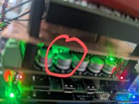
The question rises up when a friend was looking for various new power amplifier devices and had serious doubts about the lifetime and reliability of Class-D variants when he saw the modules inside the devices, the images of which I uploaded.

What experience is there here?
Do the electrolytic capacitors have to be replaced early - i.e. after a short period of use?
Or can one assume a similar life expectancy for the well-known brands as for good conventional variants in analog technology (mostly Class AB) ?

At first glance the used electrolytics are in the same kind and same price class as in PC main boards and cheap SMPS modules - go to
https://hackaday.com/2019/04/12/ask-hackaday-experiences-with-capacitor-failure/ (nichicon)
https://de.m.wikipedia.org/wiki/Datei:Al-Elko-bad-caps-Wiki-07-02-17.jpg (GSC)
https://www.robotroom.com/Faulty-Capacitors-1.html (CapXon)
Thanks for comments.

P.S.: Interesting report
https://audioxpress.com/article/fre...-amplifier-module-doubling-down-on-a-flagship
https://www.audiosciencereview.com/forum/index.php?threads/nad-m23.30114/
https://www.audiosciencereview.com/...purifi-eigentakt-is-my-dream-amplifier.25376/

Attachments

  • HYPEX nc400.jpg
    HYPEX nc400.jpg
    39.5 KB · Views: 71
  • hypex-ucd400.webp
    hypex-ucd400.webp
    112.4 KB · Views: 68
  • NC122MP Hypex-clone.webp
    NC122MP Hypex-clone.webp
    91.9 KB · Views: 67
  • Purifi_200260.jpg
    Purifi_200260.jpg
    327.7 KB · Views: 62
  • PURIFY - 1ET400A Perspective trans 880x880.png
    PURIFY - 1ET400A Perspective trans 880x880.png
    554.2 KB · Views: 56
  • PURIFI 1ET400A.webp
    PURIFI 1ET400A.webp
    113.1 KB · Views: 59

Suggestion / Advise for surround speakers in multi channel audio

Hi folks,
I am looking to replace my existing full range 6 inches (dainty speakers, may not be a familiar brand to all) with either of the below options:

Cuboid 6 from Optimal audio
(https://optimal-audio.co.uk/products/loudspeakers/cuboid/cuboid-6/)

Flex point FP6 from Martin Audio
(https://martin-audio.com/products/loudspeakers/fp6)

Please suggest based on your experience whether this will enhance my surround channel experience or am I better off to look at something like the below which is meant for home audio

https://www.tagaharmony.com/en/products/3589/speakers/product/9131/platinum-s-100-v-4

Room size - 20x20
Source - Marantz SR5013

Denon POA 6600A - one runs hotter

Dear Forum,

I know this is way too remote question to ask, but I found out that one of the blocks runs hotter, than the another however they sounds balanced to me.
I am using them with a Martin Logan CLSII pair.

Should I do the ,,biasing" as shown in the manual? Could this be that any of the 2SC2238B or 2SC3852's killed in action?

Thank you for your answer in advance!

Focusrite 2I2 Gen4 comparison

Comparisons of focusrite 2i2 gen4 with generation 3 and other usb, firewire audio interfaces. Mdat you can find more here: https://drive.google.com/drive/fold...QRqwCC0mRVaoLX3O?dmr=1&ec=wgc-drive-hero-goto

Attachments

  • Alesis IO26.hsw - Steps 12_1_2024 2_53_07 PM.png
    Alesis IO26.hsw - Steps 12_1_2024 2_53_07 PM.png
    130.3 KB · Views: 67
  • FW AP Analog In 1 on M-Audio ASIO at 48 kHz, 64k-point Spectrum, Hann window, 50% overlap, no ...png
    FW AP Analog In 1 on M-Audio ASIO at 48 kHz, 64k-point Spectrum, Hann window, 50% overlap, no ...png
    169 KB · Views: 66
  • FW AP Analog In 1 on M-Audio ASIO at 48 kHz, 64k-point Spectrum, Hann window, 50% overlap, no ...png
    FW AP Analog In 1 on M-Audio ASIO at 48 kHz, 64k-point Spectrum, Hann window, 50% overlap, no ...png
    164.7 KB · Views: 61
  • IMG20241130181944.jpg
    IMG20241130181944.jpg
    189.1 KB · Views: 59
  • IMG20241130182334.jpg
    IMG20241130182334.jpg
    224.6 KB · Views: 60
  • IMG20241130182357.jpg
    IMG20241130182357.jpg
    218.1 KB · Views: 66
  • iO 26 Line 1 on ASIO Alesis Firewire at 48 kHz, 64k-point Spectrum, Hann window, 50% overlap, ...png
    iO 26 Line 1 on ASIO Alesis Firewire at 48 kHz, 64k-point Spectrum, Hann window, 50% overlap, ...png
    162.7 KB · Views: 61
  • iO 26 Line 1 on ASIO Alesis Firewire at 48 kHz, 64k-point Spectrum, Hann window, 50% overlap, ...png
    iO 26 Line 1 on ASIO Alesis Firewire at 48 kHz, 64k-point Spectrum, Hann window, 50% overlap, ...png
    173.6 KB · Views: 60
  • LINE_IN L on Line (3- USB AUDIO  CODEC) at 48 kHz, 64k-point Spectrum, Hann window, 50% overla...png
    LINE_IN L on Line (3- USB AUDIO CODEC) at 48 kHz, 64k-point Spectrum, Hann window, 50% overla...png
    179.7 KB · Views: 54
  • M-Audio.hsw - Steps 12_2_2024 11_52_20 AM.png
    M-Audio.hsw - Steps 12_2_2024 11_52_20 AM.png
    142.5 KB · Views: 60
  • REW V5.31.3 11_30_2024 12_46_54 PM.png
    REW V5.31.3 11_30_2024 12_46_54 PM.png
    278.1 KB · Views: 53
  • REW V5.31.3 11_30_2024 12_46_59 PM.png
    REW V5.31.3 11_30_2024 12_46_59 PM.png
    199.7 KB · Views: 51
  • REW V5.31.3 12_1_2024 6_19_05 PM.png
    REW V5.31.3 12_1_2024 6_19_05 PM.png
    261.9 KB · Views: 50
  • REW V5.31.3 12_1_2024 6_19_21 PM.png
    REW V5.31.3 12_1_2024 6_19_21 PM.png
    342.1 KB · Views: 51
  • REW V5.31.3 12_1_2024 6_19_28 PM.png
    REW V5.31.3 12_1_2024 6_19_28 PM.png
    257.4 KB · Views: 52
  • REW V5.31.3 12_1_2024 6_19_38 PM.png
    REW V5.31.3 12_1_2024 6_19_38 PM.png
    332.7 KB · Views: 54
  • REW V5.31.3 12_1_2024 6_19_45 PM.png
    REW V5.31.3 12_1_2024 6_19_45 PM.png
    345.5 KB · Views: 50
  • REW V5.31.3 12_1_2024 6_19_50 PM.png
    REW V5.31.3 12_1_2024 6_19_50 PM.png
    344 KB · Views: 52
  • REW V5.31.3 12_1_2024 6_19_55 PM.png
    REW V5.31.3 12_1_2024 6_19_55 PM.png
    348.2 KB · Views: 47
  • Untitled - Arta 11_30_2024 6_02_00 PM.png
    Untitled - Arta 11_30_2024 6_02_00 PM.png
    105.6 KB · Views: 58
Projects by fanatics, for fanatics
Get answers and advice for everyone wanting to learn the art of audio.
Join the Community
507,589
Members
7,878,502
Messages

Filter

Forum Statistics

Threads
405,792
Messages
7,878,502
Members
507,589
Latest member
bonekrakka