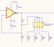
Stray capacitance at the -ve input might be less if the resistors went direct to the -ve input of the opamp and the switch had one side grounded. Hard to say really.
Assuming you want to minimize the hum you get when someone changes the setting while the circuit is on: switches from the resistors to ground.
The person changing the setting can be seen as an electrically short monopole aerial picking up electric hum fields from the surrounding, and his/her/its/their fingers will capacitively couple to the switches to some extent. With one side of the switch grounded, one side of each switch will be insensitive to this, and both sides will be when the switch happens to be on.
The person changing the setting can be seen as an electrically short monopole aerial picking up electric hum fields from the surrounding, and his/her/its/their fingers will capacitively couple to the switches to some extent. With one side of the switch grounded, one side of each switch will be insensitive to this, and both sides will be when the switch happens to be on.
Your design prevents a situation where the amplifier goes open-loop if all the switches are open so you're good there. Regarding your concern about having the DIP switches on a sensitive node, it depends on what kinds of signals you are concerned about. The resistor values are relatively low, so parasitic capacitances will likely have little to no impact on audio signals. RF signals, maybe not the case! Here at diyaudio, it's pretty likely you are NOT talking about RF frequencies though.....
A good data sheet can be your friend here -- it might provide some information regarding the stray capacitances of interest -- across the switches and switch-to--switch, so you could cobble up a simple SPICE sim to see how things behave. You'd want to include ALL the stray capacitances because the parasitic C's across each switch will add up, as parallel-connected C's.
In the end, the answer really depends on your requirements. Not knowing what those are, I'm stopping here :}