
It is a simple phase Invertor as used unsuccessfully in many power amplifiers back in the early days, using the cathode voltage to exite the control grid of the non driven side, almost into oscillation. That, in turn, inverts the anode current with respect to the opposing valve.
The control grid with the decoupling to ground, holds the grid voltage stable (ish) while the cathode moves in phase with the first valve and the second valve reacts in an opposite direction.
Lots of harmonic distortion and the idle current must be held quite high to get it to work. Usually it was found to be very unstable.
Back in 1949 Williamson tried it and returned to traditional ways, as it is not an accurate or efficient way to provide any sort of quality, distortion free output.
I don't think anyone used it since.
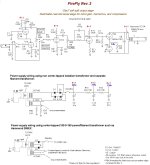
No expert in this area but having built the OddWatt EL84 SIPP amp, I can say that it is a very sweet sounding amplifier.
On the bench tests & simulations of this odd circuit.
Now THAT'S a workshop!!👍👍
6AD7 can be found for less than the 6F6G. I have a few - would offer one for testing, but I won't be back home until spring. I have a little Bogen amp that uses a 6F6 and 6AD7 in push-pull.
Lorenz took this idea to its logical conclusion with the ECLL800. Though a Compactron base could have supported a pair of power tubes and a proper phase inverter triode. Perhaps it would have been numbered 6PP10?
Lorenz took this idea to its logical conclusion with the ECLL800. Though a Compactron base could have supported a pair of power tubes and a proper phase inverter triode. Perhaps it would have been numbered 6PP10?
jhstewert9,
Thanks for the information.
My analysis of Figure 13.44 is as follows:
The circuit is nearly identical to some paraphase phase splitters, Except for the fact that 13.44 has plate to plate feedback from the p-p primary.
In many paraphase splitters, the plate loads are resistors, so the plates are not coupled to each other.
I am not a fan of paraphase splitters like that. I will explain as we continue.
In both cases, 13.44, and many traditional paraphase phase splitters, if Rk is bypassed with a capacitor, there is no cathode to cathode feedback.
For many paraphase phase splitters, if Rk is bypassed, then . . .
The input stage has dominant 2nd harmonic distortion. And the other stage has an identical transfer function, but it is in the opposite direction.
As a result, the first stage outputs dominant 2nd harmonic distortion, but the other stage is in serial cancellation of the 2nd harmonic.
So one plate has dominant 2nd harmonic distortion, and the other plate's 2nd harmonic is cancelled by the serial cancellation of the opposite direction transfer functions of the two tubes.
For 13.44, if Rk is bypassed, the only partial cancellation of the unequal dominant 2nd HD, versus the other stage's cancelled 2nd HD, is the plate to plate feedback.
For many paraphase phase inverters, if Rk is bypassed, If the paraphase outputs drive a push pull output stage, then one output tube is driven by dominant 2nd harmonic distortion, but the other output tube is driven by a signal that does not have dominant 2nd harmonic distortion.
That causes a less than desirable condition.
And now you understand why I do not like paraphase phase splitters.
Even if Rk is not bypassed, the cathode to cathode feedback is not 100% corrective.
If you can follow and understand all of this, you are doing really good.
I congratulate you!
I am sorry for the long book like discussion. Just stating that a paraphase phase splitter has one 2nd HD output, and the other stage has a non-2nd HD output, does not convince some skeptics.
Last edited:
If whatever amplifier you are using sounds OK, then that is the bottom line. Continue enjoying your system, no further explanation is needed.
But others of us need something more to go by if we are to come up with a suitable comparison. That is where an agreed upon system of test & measurement is a must. Otherwise we are simply throwing darts at an invisible target.
I’m finally on the olde side of life, so I gave away about half my very large stash of tubes in 2019, just before COVID. Gone to a friend who can use them. My heirs & successors have no idea what this stuff does. So I’m not going to be looking to find tubes to do further tests at this point.
The first time I recall seeing an example of this kind of circuit was thru a rock guitarist friend. It was a simple low powered amp, part of a guitar pedal. There was a sealed box on two leads in the cathode circuit, no phase inverter. After some testing it looked to me that a choke was in that pedal.
Then a circuit showed up on the web, it was a guitar pedal by none other than Doug Hammond himself. A way to sell some Hammond transformers.
Thankyou Jon Snell for your easy to follow description of the self inverting circuit & how it works. Many of those on DIY & the lurkers will find your effort a great help.
I tried Wikipedia, Etc to find a reference to Williamson’s exploration of self inverting amplifiers, no reference at all. Williamson’s original design is a very good indicator he was looking for the absolute best using the knowledge & devices available to him. Many would say he did very well. The Partridge OPT was an important part of the design. And the pentodes are used as triodes. Otherwise too much gain & phase shift.
Williamson also covered the possibility of amplifier common mode gain caused by insufficient PS decoupling. Something completely missed by inexperienced designers. For the curious refer to RDH4.
Self inverting amplifiers were fairly common in home receivers here in North America during the 40s & 50s for the reasons listed in my note. Maybe not in Europe, but why then the ECLL800 to avoid it?
There have been some amp designs show up where a choke has been used in the power stage cathodes. And perhaps it sounds different, could be the builder simply wanted to try something different.🙂
Attachments
Lorenz took this idea to its logical conclusion with the ECLL800.
The ECLL800 for sure wasn't designed as a self inverting PP amplifier. Instead, as the designator already tells us, it's envelope contains two BPT's (each almost similar to EL95/6DL5) and an unique µ = 1.1 triode, dedicated as the inverting stage for the 2nd BPT.Maybe not in Europe, but why then the ECLL800 to avoid it?
This tube has become scarce and expensive these days, as C. Lorenz/SEL/ITT was the only manufacturer and the tube was published at the end of tube heydays, just before power transistors flooded the markets.
Best regards!
I would say you have to load the common cathod of the differential output tubes with contant current source to make it work.
Alternatively, you can replace the constant current source with a large choke (or inductor).
Alternatively, you can replace the constant current source with a large choke (or inductor).
Your best way forward is to set up a test circuit on the bench. Let us know your results.🙂I would say you have to load the common cathod of the differential output tubes with contant current source to make it work.
Already did that. results are all in the report. But that requires you to open the pdf & read it. 🙂Alternatively, you can replace the constant current source with a large choke (or inductor).
A beam deflection tube like 6JH8 makes an accurate but low gain inverter/splitter. Cheap too. I think I got a box of them years back for $0.50 each.
https://frank.pocnet.net/sheets/093/6/6JH8.pdf
It's the equiv. of a differential pair over a CCS, all in one tube. The deflectors are like the LTP grid1s and grid1 is like the CCS current setting. (a const. Vbias to set beam current) They are sensitive to magnetic fields, so a steel shield is needed.
Last edited:
The data sheets covering the sheet beam tubes talk about there use as phase inverters for TV picture apps.
I seem to recall the HAM guys used the 7360 as the starting point for their SSB transmitters.
Double Side Band, Suppressed Carrier. But then you need a very complicated filter to get rid of one of the sidebands.
There was an RC module that people could buy to avoid a lot of complication.
The 7360 & others could be used as a modulator to generate the L-R sub carrier for FM stereo broadcast.
Don't try this at home, better in a well equipped lab.👍
Attachments
The 6JH8 has the straightest X curves, as shown. Best for linearity, and it's the most common available BDT tube.
All the endless discussions on DIY about the best splitter circuits and the easiest, best and cheapest 6JH8 never gets mentioned. Usual LTP splitters have 3rd H dist. Not 6JH8 BDT.
All the endless discussions on DIY about the best splitter circuits and the easiest, best and cheapest 6JH8 never gets mentioned. Usual LTP splitters have 3rd H dist. Not 6JH8 BDT.
Last edited:
Could you please share a schematics showing one of these BDT's as phase inverters? I'm completely dumb here, as they were absolutely unknown in Europe.
Best regards!
Best regards!
Not much to it really. See the 6JH8 datasheet. The two BDT plates ( pins 8 and 9 ) go to two load resistors which then go to B+. The plates are the outputs and nominally sit at +250V. Each load resistor times the selected plate idle current (say 7 or 10 mA each plate ) then takes that up to B+.
The accelerator ( pin 3 ) is set at +250V.
The cathode ( pin 7 ) gets a ( typical) 220 Ohm bias resistor to ground.
The deflectors ( pins 1 and 2 ) are the differential inputs, and nominally set at ground potential. For splitting, just one of them would be driven by the input signal. Although a balanced deflection could be set up with an attenuated inverted Fdbk to the other deflector input. ( An attenuator from the inverting plate back to the un-used deflector, for getting balanced level deflector inputs effectively. Doubling the output gain. ) The deflector gm ( in balanced deflection mode ) is around 5mA per V ) ( 5000 uMho balanced, or 2500 uMho for single input )
The grid1 ( pin 6 ) V at around -4V to set the total plate current. See graphs. The cathode bias resistor can effectively set this.
A beam focus electrode is connected to Htr pin 5 and gets ground potential.
These BDT tubes do act like 2 triodes internally, as the differential plate V field acts back on the beam deflection, besides the deflectors. So there is a maximum gain one can get, regardless of the plate load resistors. Unfortunately, the data sheets don't give the mu factor, but I have seen mention of mu around 6 for the 6AR8 BDT tube, which is similar to the 6JH8 tube..
Last edited:
As George has pointed out the beam tubes would make very good split load phase inverters.
But I'm thinking the beam defection circuit might be a source of noise, something for someone to try.
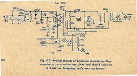
I found the 7360 balanced mixer in the ARRL Handbook of 1971. This one is set for RF of 9 MHz.
Also for George, I think he has an HP 8640, link to HP App Note 171-2, adding the HP 10514A balanced
mixer to get response down to DC. The HP 10514A is a compact balanced mix, four diodes in a ring
& two RF transformers all in a compact package.
https://www.hpmemoryproject.org/an/pdf/an_171-2.pdf
A related product is the HP 10515A, a frequency doubler. Looks like a FW CT rectifier on paper.
Sometines called a Push-Push Doubler.
All way off topic on this forum.
Anybody know what the 3rd Order Intercept is??🙂🙂
But I'm thinking the beam defection circuit might be a source of noise, something for someone to try.
I found the 7360 balanced mixer in the ARRL Handbook of 1971. This one is set for RF of 9 MHz.
Also for George, I think he has an HP 8640, link to HP App Note 171-2, adding the HP 10514A balanced
mixer to get response down to DC. The HP 10514A is a compact balanced mix, four diodes in a ring
& two RF transformers all in a compact package.
https://www.hpmemoryproject.org/an/pdf/an_171-2.pdf
A related product is the HP 10515A, a frequency doubler. Looks like a FW CT rectifier on paper.
Sometines called a Push-Push Doubler.
All way off topic on this forum.
Anybody know what the 3rd Order Intercept is??🙂🙂
Attachments
Anybody know what the 3rd Order Intercept is??
The ARRL SSB manual had an article or two on using the 6HW8 BDT tube for phasing SSB, and I recall something like 60dB suppression. The 6JH8 has noticeably better curves than the 6HW8, but this all depends on signal level. The 6JH8, 6HW8, 6AR8, 6ME8 BDT tubes use a neg. splitter plate between the plates, which does not absorb any plate current. The 7360 on the other hand has grid like deflectors IN the beam which do absorb electrons. The 6JH8, 6HW8, 6AR8, 6ME8 BDT tubes should be much quieter than the 7360 tube.
Last edited:
I enjoyed searching around for self-split PP examples and history - https://www.dalmura.com.au/projects/Valve Info.html
I prepared some sample prototypes based on a 5W line transformer, and then replicated Bob Weaver's interesting design.
Nice to see some more interest/awareness
I prepared some sample prototypes based on a 5W line transformer, and then replicated Bob Weaver's interesting design.
Nice to see some more interest/awareness
Thanks a lot for this very informative collection!
Anyway, as I said before, self splitting PP might have been of some importance under the aspect of being as economical as possible in 1950ies' mass production, when tubes and components were expensive in relation to a mean income. But it was, is, and forever will be a very poor crudge, as DIY exactly is the opposite of mass production, and as we have well proven PI designs without the inherent disadvantages.
Best regards!
Oops, a correction on my calculation of deflector gm for the 6JH8: should be 5mA per 10V differential change on the deflectors @ 20 mA beam current. Sensitivity varies directly with beam current. A single ended input on one deflector would be half that. Calculated from the datasheet X diagram.
- Home
- Amplifiers
- Tubes / Valves
- Self Inverting PP Stage Test Results