trobbins, THX for that link to a cornucopia of circuits & articles from the past.
A real good view of how our predecessors were advancing the art.
Some circuits that lasted, others that didn't. 🙂 🙂
A real good view of how our predecessors were advancing the art.
Some circuits that lasted, others that didn't. 🙂 🙂
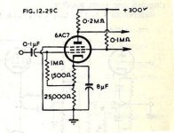
This odd phase splitter I had seen in RDH4 many years ago, so looked it up again today.
As usual, anything but HIFI but NTL interesting. Never tried it tho.
Probably work better using a 6CS6, a tube designed for that kind of app.🙂
As usual, anything but HIFI but NTL interesting. Never tried it tho.
Probably work better using a 6CS6, a tube designed for that kind of app.🙂
Attachments

How about just putting a current mirror or emitter degenerated constant Beta PNP transistor up above the tube plate load resistor to B+. Then a load resistor down to Gnd from the current mirror output or PNP collector. Similar phase currents, but inverted direction, make for inverted outputs on the load resistors. Should be pretty darn accurate. An N Fdbk from a tap in the SS output load R to the tube cathode could linearize the tube's V to I function.
Last edited:
I seem to recall a 1950ies German desktop radio that featured the ECH81/6AJ8 heptode part in exactly this service. Presumably out of economics, as the ECH81 was found in any European radio as the frequency converter anyway, thus saving additional storage of a not so common tube.This odd phase splitter I had seen in RDH4 many years ago, so looked it up again today.
As usual, anything but HIFI but NTL interesting. Never tried it tho.
Probably work better using a 6CS6, a tube designed for that kind of app.🙂
Best regards!
You might like to add the BBC C/9 (among others) to the list.I enjoyed searching around for self-split PP examples and history - https://www.dalmura.com.au/projects/Valve Info.html
http://www.bbceng.info/ti/eqpt/C_9.pdf
The BBC amp mentions distortion maximum and says '0-6%' or '0-25%'
Do i assume that the '-' is interpreted as a comma ',' ?
Do i assume that the '-' is interpreted as a comma ',' ?
Dave McDonald, a.k.a 6A3sUMMER in another thread said that he built a self inverting amp using PP 6CK4s
But offers no schematics. results, photos or any other evidence.
He told me his lap top had crashed with all his files. C'mon Dave, you can do better than that.
No backup on a USB stick? No pencil & paper stuff? If I'd gone to my Glorious Leader with that story
I sure I'd be shown the door.
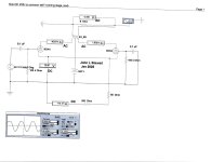
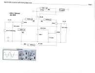
So here are the test results of a PP 6CK4 Self inverting amplifier in three modes.
The NFET version looks as good as with a choke. But the folks who were building
these circuits in the distant past didn't have NFETs. For them the choke was a
simple fix.
The resister only cathode impedance results fail badly. 🙂
But offers no schematics. results, photos or any other evidence.
He told me his lap top had crashed with all his files. C'mon Dave, you can do better than that.
No backup on a USB stick? No pencil & paper stuff? If I'd gone to my Glorious Leader with that story
I sure I'd be shown the door.
So here are the test results of a PP 6CK4 Self inverting amplifier in three modes.
The NFET version looks as good as with a choke. But the folks who were building
these circuits in the distant past didn't have NFETs. For them the choke was a
simple fix.
The resister only cathode impedance results fail badly. 🙂
Attachments
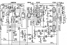
The only German radio I know of with an ECH81 as a splitter was the Koerting 430W from 1954.I seem to recall a 1950ies German desktop radio that featured the ECH81/6AJ8 heptode part in exactly this service. Presumably out of economics, as the ECH81 was found in any European radio as the frequency converter anyway, thus saving additional storage of a not so common tube.
Best regards!
But here the Heptode part is the gain stage and the Triode runs as a cathode coupled paraphase into a pair of EL84s.
This set is also remarkable as it abuses the triode of an EABC80 as an additional IF amplifier stage ...
Attachments
Here's a self split I played with a while ago:
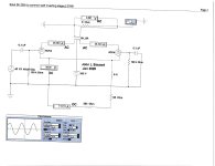
I recently acquired this amp kinda by accident, for spare parts. But after I received it I knew it looked familiar somehow and eventually traced it to this thread! So I thought it would be fun to run a few tests on it, and see what could be done with it. I had to reverse engineer the circuit, so Nigel can correct me if anything is wrong.
You can see from the results the -3dB bandwidth is about 40Hz to 6kHz (1Vrms into 8 ohms), which I guess isn't bad when you're using a power transformer as the output transformer.
Distortion is pretty dire, struggling to make even 1W if you don't mind...
You can see from the results the -3dB bandwidth is about 40Hz to 6kHz (1Vrms into 8 ohms), which I guess isn't bad when you're using a power transformer as the output transformer.
Distortion is pretty dire, struggling to make even 1W if you don't mind...
OddWatt, a somewhat popular brand, same as Merlabs find was/is sold here
in US/Canada, same circuit but with different tubes depending on how deep our pockets were.
Still used the LM317, but a much better OPT.
in US/Canada, same circuit but with different tubes depending on how deep our pockets were.
Still used the LM317, but a much better OPT.
Thanks Merlin. Interesting comments in that, including the microphony of the 12AT7 variants. And that C/9 module uses 29dB feedback for hi-fi performance, albeit for 100-150mW line driving. Perhaps a nice prototype option for a dedicated headphone amp, although once again it is also reliant on a damn good output transformer.You might like to add the BBC C/9 (among others) to the list.
http://www.bbceng.info/ti/eqpt/C_9.pdf
A medium to high voltage transistor makes a great concertina splitter easily driving 4ma from a KSC1845 and 12AX7.
115v B+ yields 55v p-p each side.
KSC3503 can go up to 300 volts
115v B+ yields 55v p-p each side.
KSC3503 can go up to 300 volts
Thanks for the clarification, Sorento 👍 ! As I said, I seem to recall...The only German radio I know of with an ECH81 as a splitter was the Koerting 430W from 1954.
Best regards!
Chill out, really.Dave McDonald, a.k.a 6A3sUMMER
Always the best,
Chris
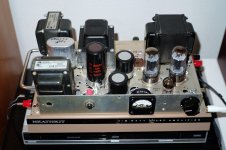
THX for the photo of your PP 6CK4 self Inverting Amp. Looks like the photo was taken in the last 24 hrs.
Why didn't you put this on DIY earlier as evidence of your work? That would have helped a lot.
Since the build seems to still exist is it possible to get some measurement date & a schematic? THX 👍
Why didn't you put this on DIY earlier as evidence of your work? That would have helped a lot.
Since the build seems to still exist is it possible to get some measurement date & a schematic? THX 👍
- Home
- Amplifiers
- Tubes / Valves
- Self Inverting PP Stage Test Results