Cec Amp71

Hello,

I have just read some piece of information I found interesting. It is taken from http://www.rcm.com.pl/cec/cec_main.htm , and it concerns CEC's new integrated amp, AMP71. The original text is in Polish, here is my (poor 🙁) translation. I may have messed it a bit, I believe HPotter would do a better job. Anyway, here it is:

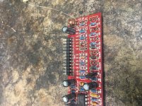
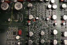
AMP71 works in Class-A, giving 200wpc max, without generating huge amount of heat. Enough to say, that heatsink temperature of a working amplifiers does not exceed 40 deg. C. What's more interesting, all A class amps, with power exceeding humble 30wpc, have large cases with enormous power supplies. AMP71 has traditional ps with 160000uF caps and two highest 🙂)) quality toroid transformers (650W each). Using two toroid is caused by fully symmetric design, including speaker terminals, not connected to the ground. Basic idea is very simple from theoretical point of view, yet its implementation is not that simple. To make long story short, signal is amplified by single bi-polar transistor, working in pure class A. It amplifies signal from input, which basically means that AMP71 does not contain pre-amp section, and the whole amplification is done by single gain stage without feedback. (...) The most interesting part is how to gain 200W in class A using only one gain stage. As we were said by designer, Mr. Carlos Candeias, gain is set between 40 and 50, and with given 100mV input sensitivity results in 5V max on the output. So where is that 200W coming from? The gain transistor is supported by current source made of 8 transistors per channel, that can easily generate 200W while working in A class (its very high impedance does not influences the signal). Roughly speaking, the power transistor works as switch controlling the
current transistors. The whole process is controlled by detecting output signal and informing the current source about changes, that are apropriately amplified. (...)

Does it sound familiar? Any comments, guys?

Regards,

Marcin.

How to build a Gain module for Subwoofer Amp without hum problem (TDA8950)

hi members ...

i need to build a gain module to compensate for the input sensitivity of my TDA8950 (dont know why it has low input sensitivity). But now the problem is after the low pass filter the signal will pass into an inverting op-amp section which has gain of around 8db and this has given me Hum problem when the subwoofer volume potentiometer is turned more than 60%.

Low pass filter is 2nd order LR and there is an inverting summing opamp stage that combine the Left and Right channels and this stage has unity(1) gain ... only the final stage operates with gain while inverting back the signal phase

thanks

MA CHBW70 sims - vent air speed

I got a couple pairs of drivers from Scott recently, including a pair of CHBW70.
I put the data into WinISD to the best my knowledge allows. I got the red warning about dodgy parameters.

The model seems to work. The curve looks as one would expect soi believe the parameters are ok. Surprising LF extension in small enclosures the only 'alarm' that rang for me. But hopefully this is correct as Scott did mention they would go down into the 50s.

The biggest issue I see is the vent air speed. Even with a 1w signal, the curve just shoots up off the graph intimidating huge air speeds. Maybe this is a function of the parameter input being bad?

Best regards
Jim

Small 12-19V 15-25W power supply (similar at Neurochrome smps-86)?

Looking for a 12-19V DC output power supply, rated 15-25watts, for powering a low powered ITX motherboard.

Neurochrome SMPS-86, fitted with Meanwell 12V power modules seems attractive.

Any other better options for me, with similar dimentions.

I'm trying to do an internal power supply as opposed to an external linear power supply in a small enclosure.

Thanks

FCAM123 line source for compact outdoor 12V application

Hi! I'm thinking of experimenting a bit with line sources for outside use.I read from martinsson that the FCAM123 sounds good outdoors and it looks like a quick build so I already ordered 12 faital Pro 3FE25-16s. Only 12 because my plan is to divide the line array into two smaller, 6-units long arrays that one can attach together to form again the 12 unit array. This way, one can make a mono stack for electronic music (my plan is to use a THAM12 as subwoofer) or have stereo set-up for other applications or locations.

I have been reading about how line arrays behaviour can be improved by means of delays, shading and progressive crossover settings. I'm considering using an NL4 conenctor for each half so I can apply different settings to the lower 4 and the 2 upper faitals with the aid of a minidsp 2x4. This way, when both are attached I'd have 4 zones with 4-2-2-4 speakers each.

Do you have any experiences with such set-ups? Any stuff I should take into consideration?

Thanks!

Hafler 1977-80s Paint

I'm restoring some David Hafler amplifiers and found a paint match , I think.
The DH paint looks like from 1972-3 GM auto paints. A very dark metalic olive. The Duplicolor 'DE 1651 Cast Coat Iron' shown in pic is very close. We'll see how well it matches the front panels/knobs. Its a high temp ceramic paint.

Attachments

  • 2E27C3C2-A97F-43CA-812A-F101F4FAC567.jpg
    2E27C3C2-A97F-43CA-812A-F101F4FAC567.jpg
    525.3 KB · Views: 374
  • 3D495AA2-4B9C-4415-81D1-7B7C8DA33C99.jpg
    3D495AA2-4B9C-4415-81D1-7B7C8DA33C99.jpg
    731.5 KB · Views: 372

DSC1- V2.6

I have this DSC1 V2.6 for sale, it is new, with tantalum resistors and transformers LL1684. For personal reasons, I won't have time to finish it.
It cost me 542 euros with transport.
I can break away from it with 300 euro + transport + 4% paypal.
Thank you.

Attachments

  • 20200322_103311_resized.jpg
    20200322_103311_resized.jpg
    361.9 KB · Views: 291

Anyone Know what LED this is Krell S1200

I was working on Krell S1200 output section and inadvertedly damaged the LED diode on the board. They are diagnostic diodes for use internally at Krell I think. I replaced it with a slightly different one from a car stereo . The original has 1.6v drop and car stereo one has 1.75. I had replaced bank of transistors due to hissing caused by high DC offset going into the output signal cap but still getting .15v dc offset which is the difference of the diodes (was previously getting well over a volt before replacing transistors).. With alot of modern diodes being sold for light output for lighting it seems like it may be tricky getting the right one. Tried contacting Krell but got corona virus message and they are not there according to message. Anyone know what these might be?

Attachments

  • IMG_6893.jpg
    IMG_6893.jpg
    992.1 KB · Views: 86

Plans for L Cao F6

What enclosures would people recommend for the L Cao F6? I see a few other people have used them in Karlsonators, what other options are there please? I believe the FHXL would be "OK", but not great, any other ideas please? I've not found any enclosure plans specifically for this driver. Specs are here:

L.Cao LAOCAO F6 6? 12W Full Range High Sensitive Speaker W/ Paper Cone

Building a cheap 250W dummy load

Hey dudes.

I was planning on making a cheapo dummy load like following:

Two 3.9 ohm 50W wire wound resistors in series, installed on a large heat sink taken from a scrapped 100W mono amplifier.

This would make a nice 8 ohm 100 W dummy load, I think.

I'm planning to make two sets, and connect them in parallel, for a 200W 4 ohm dummy load.

But here's the kicker... I need 250 W. So I was thinking of submerging the bottom halves of the heatsinks in water. No risk of shorts or anything like that.

What do you think? Could it work?

Two Jeff Rowland 12's from one SPS ??

Long story short, I have semi-inherited a Jeff Rowland Model 12 amp.

BACKGROUND IF YOU CARE :

This "one" Model 12 unit is actually four separate boxes: two switch mode power supplies and two amps. The power supplies are connected to the amps by weapons-grade umbilicals.

One power supply is dead dead dead, and has been dead for years. Many, many attempts to have it repaired have failed, and heck I've been trying since last November just to get someone to return my calls. Forget Jeff Rowland or any "authorized repair centeers", I think they're hiding behind the door when you try to reach them.

Rowland does not publish schematics, or offer any assistance whatsoever.

What I've eventually learned is nobody messes with these JR switch mode power supplies, even Rowland in the past has "rebuilt" them as linears, so you sent your dead smps in for repairs, he charged a fortune and you got a linear back in that same chassis.

THE REAL QUESTION :

Can I drive both amps from the surviving SMPS?

I haven't delved into JR's SMPS design too deeply (not as if you really can), but it seems plausible.

I'm in a standard size family room (12x18 maybe) type space with pretty efficient speakers (>95dB) and just don't crank Led Zep like I used to.

This would require spending a good bit of time sourcing the connectors and building a proper split umbilical. Mocking one up properly looks like it would take almost as long as shipping the connectors, so might as well just do it right the first time.

RELATED THOUGHTS :

Dead JR equipment, since it can't be fixed, has an approximate market value of $zero, give or take shipping. The boxes are cool CNC machined aluminum, kind of like Lego the way they go together to make different JR equipment. But these are the stubbiest of the JR boxes, so you cant jam much in there if you're repurposing them.

I would hate to immediately fry the good SMPS, because we've been using it to troubleshoot the dead SMPS.

On the other hand, I'm functionally dead in the water unless I really get into mono.

The other down-the-road thought is, ditch the dead SMPS and build a nice linear PS into that box and use IT to drive both amps. I'd already have the umbilical!

But seriously .... thoughts on the original idea of driving both amp modules from the one SMPS?

Thank you.

Inverting Transformers Tubelab SSE

I am planning on my first tube amp build, I have decided on a Tubelab SSE and the chassis design I am working on has the power and audio transformers inverted (upside down). They would be separated from the tubes/other electrics by sheet metal.

I know tube amps, especially SE are very picky about the transformer location/orientation. Can anyone tell me the implications of inverting the transformers?

When is a 200W Power Resistor the Size of a 100W Power Resistor?

A decade ago, I bought some 200W power resistors. Aluminum extruded, 165mm long, rather heavy, to build a dummy load with.

This month, I bought four more of what appeared in the listing to be the same thing (even their chart showing different wattages and sizes showed the 200W being 165mm long). What I received however was only 100mm long. According to the chart, these are 100W units. But they are marked exactly with the same part numbers as my 10 year old resistors.

Either the laws of physics have changed in 10 years (doubtful), or somebody made an error in labeling.

The seller investigated and this morning informed me that this is correct. I don't believe them. The parts I received don't even match specs with their own resistor chart.

I'm reluctant to build the dummy load with these resistors, but if I try to buy them again, I'll probably get the same thing all over again.

So what do ya'll think? Labeling error, or improved physical materials?

Peerless HDS Tweeter too harsh, (Nomex 164)

Ok...I have posted this issue in a couple places...here's what I have figured out so far. My ears are sensitive...my Old ACI's Sapphire III's (Audio Concept Inc) were DVC and when one VC wasn't working because of a bad resistor, I could here it. (The difference in the volume.) I'm sure probably most here, could too!

My build is the Troels Nomex 164's I increased the R1051 from 1.1 ohm to 3.3 ohm. Still at loud levels it hurts my ears after a time. (CD's not so much.) Also, I listen from my Ipod regularly...so I know that is a consideration.

I am running 2 (or 3 depending on what I play) Adcom 2535 amps, with a B&K Ref 30 Pre-pro) with 200 watts going to my stereo pair!

I really want to build the Elsinores...but until a couple days ago thought these HDS tweeters were too "bright". Now I am sure it has to be the xover.


I used Audyn Plus caps, so I am going to try the Silver Janztens on the tweeter section. (The price difference is $8 each I think, compared to the Supremes)


Also I had issues with the solder strips Troels recommended, but I tested the ohm load on my speaks and they are right at 4.5 ohm so I don't think thats the problem!

I really like the way these HDS tweeters sound...so any help would be appreciated!


PLEASE READ THIS.....I have never listen to and enjoyed music at low to moderate levels like these speaker produce! (I have an 18 month old so I have no choice..😉 ) In any case I cannot believe how good these sound at low and moderate, or even mid high volumes. It's just when I really crank up the 200 watts that they start to fatigue. The ACI's didn't have this issue!

Therefore I am convinced it's the Cap...keep in mind the harshness is subtle!


Thanks in advance for any input...and thanks for these forums...freaking AWESOME!!!!!

Electric wiring Thorens 165, multi-meter use during reparation.

Accidentally I damaged a Thorens 165 record player. During repair of that part of the tone-arm I accidentally cut the wiring, so I had to rewire.

Also I wanted to swap the positon of the RCA-outlet of the backside so the channels would be in the same position of the amp. Now I had to desolder those RCA-plugs and resolder after swapping them from left to right, the red plug on the leftside (right audio channel), the black on the rightside (left audio channel, plug outlet on the rightside, as on my amp).
Now I am not a pro and I am learning to solder now but I want to controll the work before I can go further.
I don't want to do a lot to find out later that I made a mistake earlier on.

So I soldered these RCA-plugs after swapping their position in the wooden holes at the back. And now I want to be sure that this connection works with a Mulit-meter. One RCA plug ( I think the red one) gave a reading of 20 or more volts, the other hardly...again I am a rookie at this stuff, I want to learn. So is it normal or do I have to resolder the other plug? If I am doin' it wrong...please tell me cause this is all new for me.

I just want to be able to do this repair because of restoring a good recordplayer but also to be able to do this myself properly. So how do I use the multi-meter to check if my repair worked out? And what would be a proper volt-reading of RCA-connection from the wire-chassis to the RCA outlets on the back?

(The RCA-outlets are by the way not original, originally Thorens had a RCA-wire (grey) that went from the
bottom-plate to the amplifiere. The RCA-plugs here are a modification of later times '80ies/'90ies or later)

In which kinds of e-waste you can find transformers that work well for tube amps?

1st of all:


Hi everybody,
the reason I'm here ist that I set myself the objective to somehow make a tube amplifier to be mine, thats big enough for my room of 20m². Because broken ones are already too expensive the only way might be, to make one by myself so not to be here in this board would be much harder to explain. The will be quite a few questions coming up, this seems to be sure, thanks for your help in advance 🙂.


The 1st one is about sources of suitable transformers. I hope to find out about a commonly occuring electrical waste, that contains them. Is there anything coming up in your minds about this? Just perfect would be, if the ones in tube TVs would do the job. Because there are so many even just standing right next to the street in the whole city that the chances I would guess to be not that bad
to find some which fit to ones respective kind of tubes perfectly and do the job great.


So, do you have ideas or experiences on this how to get those transformers for free or almost for free?


Thank you a lot!

Inductor series restistance, effect on Qts, 2 identical drivers in series

Hi all,

I couldn't find a definitive answer to this after searching, so here goes.


My example:

-2 identical 8 ohm woofer drivers wired in series. Each has a Qts of 0.35.
-An Inductor is in series with both of them with a series resistance of 0.6 ohms.

Now I know the Qts doesn't get effected by simply putting them in series, (ie: it remains 0.35) however, what is the effect of the 0.6 ohms on both drivers' individual Qts?

If it was only one driver used it would be 0.6 ohms in series with 8 ohms. Driver Qts becomes APPROX 0.38 (as an example)

But in the above example its now 0.6 ohms in series with two 8 ohm drivers in series. (16 ohms)
What will each drivers Qts become?

Sort of hard to explain but I hope it makes sense. 🙂

Any help appreciated.

Thanks.

Loading plugs Perreaux SM3 Preamp

I have some difficulty determining the MC cartridge loading plug values for my cartridges. The manual states that both MM (low gain) and MC (high gain) have an input impedance of 47kOhm. When I measure the resistance at the RCA terminals I get the following values: MM 460kOhm, Load 55kOhm and MC 55kOhm (not sure if this is the proper way to measure it).

When I simply plug 100Ohm in the Load terminals (to match my Denon DL-A100 MC cartridge) the volume is significantly lower than with my Denon AU-S1 SUT connected to MM (the bass is more present with the SUT).

Am I overlooking something? Are the load plugs not simply in series or is the MC impedance not 47kOhm, but 460kOhm?

Thanks for your help.

P.S. I am not very technical, so please be kind 😉

Attachments

Output problem with Audiosource Amp 100

Hi,

Been a whhile since I posted on the forum but I need some help to troubleshoot a problem with an Audiosource Amp 100. My brother in law was using this amplifier, it was preveiously mine but I wasn't using it so I let him use it, and he didn't notice the situation because it was just background music in his gym. I took it and cleaned it up and noticed that hte 6800uf capacitorson the power rail wer starting to swell. After the cleaning i connected it and noticed that the output was lower; most noticeably the bass out put and level was a bit lower on the right channel.

I decided to change those caps with the Nichicon replacement caps recommended in the modlist that is floating online thinking that this may be the issue. However this didn't solve the issue. I wanted to know if anyone can direct me as to what other faulty part may be causing this issue.

Thanks.

Transformer selection

I have done some searching on the forums but have not been able to figure this out. I have built linear power supplies using conventional center tapped transformers but have not used toroidal transformers with double secondaries before. I have built a Diyaudio PSU for my F5 using an Antek AS-4218 transformer which has 18 volt secondaries and it puts out 24 volts on each rail. I have ordered a Broskie power supply to use with a BA2018 preamp and I am trying to select the transformer. I will probably use a 50va as I believe this should be sufficient power for the application and was going to order an 18-0-18. Is there a formula that can be applied to calculating input/output for dual rail power supplies? Thanks for any input anyone can supply me.

  • Locked
COVID-19 WE HAVE TO TEST EVERYONE

Vo' - the Italian town that defeated coronavirus

Please spread the word to local Gov. etc.(& National ) and Health Authorities!

We've got to do this as I heard a Prof. in Itally at 2AM this morning on CBC radio talking about it.

He said you have to TEST EVERYONE do to spreaders (people that don't show symptoms) and of course keep testing those people till they are NEG.

There are only 5K ventilators in Canada & 170K in the US

We can lead by example, please do this and let everyone know in the world what is going on here!

It will save many lives, jobs, and of course $ with our economy now down.

Thanks very much,

Sincerely,

Randy Yauck

Looking for 90's EAW-style steel grill (5-6mm holes)

As title says, I'm looking for ~1.5-2mm thick steel mesh (no skimpy aluminum or thin steel) with 5-6mm holes, around 14x30 (can cut down if larger, or perhaps custom order?)

LEuhBGE.jpg


I found one example on Parts Express, but not sure if it's close enough to match some EAW's.

Parts Express Flat Metal Grill Pair with 6mm Round Holes - 22" x 30"

If nobody chimes in, I will just order that since at >10' away you can't tell anyways I feel ...

Thanks!

New plate amp problems

A number of years ago I built a subwoofer using the Peerless 12" xls long throw woofer with matching passive radiator. I put a kg-5230 300 watt plate amp in that I bought from Madisound. The subwoofer work wonderfully for many years when a couple of weeks ago the amp gave out. I bought a SPA500 amp from Parts Express with 500 watts and installed it last week end. At 75% gain this amp is just audible. At that kind of gain my old amp would have broken windows. I've got a email into Parts Express about the problem but haven't heard back yet. Changing all the setting does not do much for the volume. Am I doing something wrong or is the amp possibly bad?

Any suggestions on how I can test this amp to see if it's bad or not?

Thanks

Big Quad Headphone Project

I'm a fan of Quadraphonic headphones and own a few.

My favorites are the goofy big Capeheart CH-4C phones I'm wearing in the pic below. They are large, comfy and ridiculous looking. They also sound like poop. 😀 That's no surprise as the drivers are basically cheap transistor radio speakers. They sound just like you'd think, very midrange with odd peaks. (I have measurements)

So I have decided to swap out the original drivers with a set of 50mm Peerless headphone drivers. This takes a bit of adaptations, as the original diver are ~56mm in diameter. I've made some "calamari rings" out of dense white foam to mount them. This is working out well.

Question: Should I remove the plastic fins in front of the driver? I have Pioneer headphones with plastic parts in front of the drivers, tho not a full as these. Will these louvers make much difference? What are your thoughts?

Attachments

  • quadphones.jpg
    quadphones.jpg
    76.6 KB · Views: 417
  • hole.jpg
    hole.jpg
    85.2 KB · Views: 381
  • 2 driver.jpg
    2 driver.jpg
    95 KB · Views: 380

Current commercial SS amps 2020

I had a friend ask me for a recommendation of a current commercially available stereo amplifier. Something with reasonable power, say 100-200watts in a price range less than $1000.

I realized that for a long time now, I have not purchased or even looked at purchasing a commercial amp. I have either built my own amps, or modded/rebuilt amps from long ago.

So are there any commercially available stereo amps anymore? Or does everyone just buy a AV receiver and use whatever amps are in there?

Would a non-DIY person today buy anything new? Or should they just search ebay for hafler, adcom, SAE, etc. etc.?

Thanks, gabo

reduce Electrocompaniet EC 4 Gain

Hello !

I have a pair of AW 60 blocs that are configured for mono use and a EC 4 as a preamp and they have way too much gain, moving the volume only the slightest with a regular cd player gets my 66 studio monitors way too loud and they're no sensitive speakers at all.
EC actually put out several versions of the aw-60 and they had different gain values so I started by getting both blocs to match the lowest gain version they offered (I used one I worked on before as an example). This gives me a little improvement but it's still too much and I would like to reduce the gain of the preamp as well. As there are no schematics out there I'm in need of some guidance.

Does anyone have a schematic for the gain stage, or have any idea on which resistor values to play with in order to reduce the overall amplification ?


Thanks 🙂

MUR860 equivalent

Hello,

I live in Kerala, India where it is hard to find the parts to build a gainclone. I've still managed to get most of the parts except the recommended MUR860 diodes. Is there a more commonly available equivalent for this component? Perhaps a fellow DIYer in India could suggest a place in India where the MUR860 might be available?

Thanks!

Mahesh

Staining veneer

I have finally finished the woodwork for my latest project, and I’m now ready to put some veneer on the naked MDF and plywood carcasses. I have decided on raw veneer and hide glue, which I found worked very well on my first pair of DIY speakers, nearly twenty years ago. My plans are to use black ash for the faceted baffle, and a nice oak on the rest of the boxes.

My first question is about the black ash veneer. Ash has a nice grain, takes stain well and is cheap, so I’m thinking of buying a sheet of natural ash veneer and staining it myself. Is there any reason not to do this, and buy ready-stained veneer instead? Secondly, would you advise staining the veneer before gluing to the carcass or after?

The black-stained veneer will directly abut the oak veneer, so I am concerned by the possibility of bleed-through of the black stain into the natural oak when I am rubbing oil into the veneered speakers. Bearing this in mind, would there be a preference for spirit-based or water-based stains? Or is it more a matter of just waiting long enough for the stain to dry completely before applying the oil?

Finally, I would prefer to cover the sides and rear of my boxes with single sheets of oak veneer, rather than mess around with book-matching. The thing is, the cabinets have ended up 34cm wide, and I’m struggling to find a supplier of crown-cut European or American Oak veneer sheets that are more than 29-30cm in width. Can anyone recommend a supplier (preferably in the UK) that would stock it in this width? Or am I being too optimistic?

Thanks,

Alex

Can a noob build something from scraps?

Greetings all

So I have this amp with crumbling printed boards I've been trying to fix. There is mostly working components but they are literary falling off of the PCB

Question is if it would be possible to build something simplified from the scraps as the cabinet, PSU and heatsinks, pot, etc. etc. is there and working fine. I was thinking stripping out all electronics besides pcu and build something from the power transistors and whatever can be used, on a proto board or even p to p.

I've been reading and looking around at circuits but this would mean designing circuitry, witch I could not do solo. I have received a good bit of help here in my attempts to fix it so I thought I should seek some advice before delving into something too advanced

Thanks in advance

Orion 250 hcca gen 2 power supply blown

Hello,

I have a gen 2 Orion 250 hcca that appears to need extensive power supply repairs, at least.

It appears that one side of the clamped transistors (FETs I think for this amp) are gone (several show a short), and perhaps several on the other side. The board shows some related damage, but looks to be usable. I think rectifiers are in this area too and may need to be replaced.

The small transformer standing on end is burnt up, I will probably have to order and wind a new one.

Several fluid electrolytic caps are obviously in bad shape. I already have all such caps for this amp on hand.

I do have access to several working versions of this amp, which should help.

Questions are:

1.) How best to start with repair.

2.) Replacement part suggestions for FETs, rectifiers, transformer core/winding, etc. I suppose I may be able to figure this out but any suggestions are appreciated.

Thanks in advance for any help or feedback.

Attachments

  • 05EE06CE-F3B5-4733-988C-10CA1F9313FA.jpeg
    05EE06CE-F3B5-4733-988C-10CA1F9313FA.jpeg
    762.8 KB · Views: 171
  • 03DF198B-ABE9-4AEE-8A98-F43614E8F898.jpeg
    03DF198B-ABE9-4AEE-8A98-F43614E8F898.jpeg
    786.6 KB · Views: 184
  • AF8ED912-98FD-43B4-A52D-E9E9702D2013.jpeg
    AF8ED912-98FD-43B4-A52D-E9E9702D2013.jpeg
    722.3 KB · Views: 169

Noise degradation when adding gain stage to tube crossover

I’m adding a gain stage and buffer to a tube crossover.

Initially I put the gain and buffer stages after the filters but the degradation in SNR was significant. So, I moved the gain and buffer stage to before the filters.

While better, the SNR is still significantly degraded compared with the filters on their own.

Below are the schematic for the 125Hz to 14kHz section, amplitude vs frequency before and after and 1kHz real-time analysis before and after.

For the real-time analyses I’ve adjusted the input level to match the output levels.

Without gain and buffer stage: noise floor around -118dBFS, noise 0.11% and THD 0.024%.

With the gain and buffer stage: noise floor around -92dBFS, noise 1.11% and THD 0.2%.

The increase in THD I’d expect with the common cathode stage in there.

However, the noise has gone from 0.11% to 1.11%. The noise floor has gone up by 26dB.

I haven’t connected the crossover section to an amp yet to see if the increased level of noise is audible. Maybe noise 75dB below the fundamental is OK.

Is this the best I can expect or is there a better way of doing this? Different tubes? More supply filtering or a regulated supply?

Attachments

  • schematic.png
    schematic.png
    96.9 KB · Views: 67
  • Amplitude vs frequency no gain and buffer stages.png
    Amplitude vs frequency no gain and buffer stages.png
    112.6 KB · Views: 67
  • Amplitude vs frequency with gain and buffer stages.png
    Amplitude vs frequency with gain and buffer stages.png
    124.9 KB · Views: 72
  • RTA no gain stage and buffer.png
    RTA no gain stage and buffer.png
    75.9 KB · Views: 62
  • RTA with gain stage and buffer stages.png
    RTA with gain stage and buffer stages.png
    72.8 KB · Views: 68

Custom DIY 8" Fullrange Driver

FA80 Fullrange

As new 6.5" field coil design pending numerous fabrication from my workshop.

So I decide to carry on with my 8" full range design and fabrication.

An externally hosted image should be here but it was not working when we last tested it.

An externally hosted image should be here but it was not working when we last tested it.


Do note, FEMM is using N40 for simulation. But actual magnet grade is a N45, I should get about +0.3T more to the values i got from FEMM. Wouldn't get significant increase in guass using N45, probably due to fact that steel permeability reaching its limits.

An externally hosted image should be here but it was not working when we last tested it.

An externally hosted image should be here but it was not working when we last tested it.

An externally hosted image should be here but it was not working when we last tested it.


Folding the cone, winding the voice coil.

An externally hosted image should be here but it was not working when we last tested it.


Pheonlic Dampers

An externally hosted image should be here but it was not working when we last tested it.

An externally hosted image should be here but it was not working when we last tested it.

An externally hosted image should be here but it was not working when we last tested it.

Is it aperiodic or isobaric or both?

I am looking for help identifying an encloser type I havenever seen before. I have a per of towers that I am rebuilding. The were speciallymade for a studio. They look like a takeoff of the Dynaudio Consequence. They area 5-way meaning you can see 5 different speakers. In the consequence there aretwo 30w100 in an isobaric ported box. In my setup I have one 30w100 loaded in asealed box connected to a second seal box by a verovent. After re-foaming the speakers,they did not sound quite right. Upon further digging I found a second speaker. Thereis a 21w54 loading the second sealed box. First, I have never seen an isobaricusing two different type of speakers let alone two different sizes. I have alsonever seen an isobaric setup separated by a verovent. Has anyone ever seenanything like this?

Not audio related.

I hope there is someone with greater understanding of this matter here.

Long story short. I am into classic cars and especially Volvo 1800. Those lack a third brake light and now I have seen too many rear ended, so I need to do something about it. Sure there is an easy way to find something that fits, but I rather go the long way and create something like it was designed with the car from the beginning.

I am trying to figure out the wattage values for R5 and R6 and I don't like the values I come up with as those are some big resistors. I am trying to feed the array with 2.2 to 2.4V and from what I understand I can manipulate the resistance accordingly to obtain this.

The 3W LEDs have 2.1V forward voltage and 350mA forward current. R1-R4 are 1/8W 1 Ohm.

Thank you for any help I get.

Attachments

  • 49692453186_2d7c1ab93a_z.jpg
    49692453186_2d7c1ab93a_z.jpg
    23.5 KB · Views: 196

Mid-dome directivity mismatch? (Vituixcad simulation)

Hi all,

For a 3-way project I would like to try a mid-dome. I have used the Dayton RS52AN-8 to simulate the response in Vituixcad.
But I run into a problem with the directivity, where I would like your insights on.

To describe troubleshoot the directivity, I will post the procedure I used to come to the results. Imaged from the results can be found below.

First:
1. I used the measurements from Dayton Audio RS52AN-8 | HiFiCompass
2. In Vituixcad --> used SPL-trace to get the .frd file.
3. Simulate half-space response from Enclosure tool in Vituixcad. I used two possible designs. 2 SB17NAC-8 in parallel (2x 6") or a Dayton RS225-8 (8").

4. Simulate off-axis response for the woofers via the Diffraction tool in Vituixcad. A guide can be found here: YouTube
5. As a tweeter I used the Vifa NE19VTS-04, also SPl-traced from the measurements at Hifi-compass. Vifa NE19VTS-04 | HiFiCompass
6. Simulate the speaker response in Vituixcad with EQ and linear-phase XO's. XO's are at 667 hz and 4000 hz.

The result can be seen in the pictures below. I marked the directivity problems in red boxes.
The results is practically the same when I used the infinite-baffle measurements for the mid-dome and tweeter.

Now I wonder, is this problem the result of my procedure or caused by using measurements in a wrong way.

Maybe I don't understand how mid-domes should be used 🙂. Anyway, I hope you experienced guys are willing to teach me.

Attachments

  • middome simulatie directivity probleem.png
    middome simulatie directivity probleem.png
    199.2 KB · Views: 371

What amp should I be looking at for 4 ohm?

I have a 5.1 Home theater set up, running on a Denon AVR-x2400H.

My speakers dip down to 4 ohms, even lower at some points. (Zaph 5.3T, Zaph 5.3C, and surrounds).

I feel like my speakers can do better with a different amp. It feels like when I push the speakers hard, my denon can't keep up.

What amp board would you recommend? Class D? T? And is there a way I can go full on 5.1 through these boards? I am totally blank.

I have seen TPA3116D2 mentioned around a lot, will that work better than my denon?

DIY Amp help, unsure about where to start

Ok, so I've been speculating a lot about diy amps, but never actually made anything. But now I'd like to do something for real.
Im thinking about something of the Fender Blackface variety, something not too complex, but none of the designs have the things I'm looking for, so I'd like to build these features based on an existing design.
I'd like an amp with Treb/Mid/High EQ, as well as Gain and Master controls, but as already mentioned i haven't found any designs that have all those things, so I'm unsure what to start with, and how I'd tack those things on, or if it's even possible, any pointers?

Direct Out adding? Help

Hi All!

New to this forum, thought I’d start my hello with a project!
I have a Yamaha MQ1202 (1980) and Im trying to add direct outs to each channel. I managed to get hold of the schematic and found a point I though was good; post an electrolyte cap which was post IC2 (4558) and that was all post Channel fader & eq.

I took the sig and a near by earth to a jack socket that was previously being use for HI - Z in, when I plugged it into my interface it was pretty noisey, quiet and bit crap sounding when using a dynamic microphone. I’d like to use my interface as AD/DA and not for gaining and utilise the preamp in this desk.

Any help as to where I’m going wrong and troubleshooting would be great as I’m really new to audio electrics. Electrician by trade but this is a different world!

Many thanks!
Dan

Transistor Noise Figure for Reverb circuit

I am trying to select a low noise NPN TO-92 transistor for use in a reverb recovery circuit. Source impedance is 2.575K Ω, source resistance is 215Ω, signal level is ~4mV. Using the Horowitz-Hill table for low-noise BJT transistors suggests that a 2N3904 transistor would be excellent for that application, with a voltage noise of 1.9nV√Hz and current noise of 0.68 pA √Hz. But the datasheet for the ON Semi 2N3904 quotes a Noise Figure of 5 db @ 1KΩ, which I calculate translates to 5.9nV√Hz. That is significantly higher than the H-H figures, which would indicate a total noise of 2.02nV√Hz @ 1K Ω. Which one is correct?

How much can one exceed max dissipation?

I've been repairing an old Ampeg M15 - found a blown OT. I was told on the forum that any 6L6 push pull OT transformer would do and to pick an OT from similar wattage (30w) Fender circuit - so I did. Hammond sells a 4k OT for similar amps like a Vibrolux. ( Follow up conversations claimed that from the OT213 model number, the evidence points to a 6.6k OT. ) Sounds pretty darn good BUT, I ran the VTLADYI load line calculator and it implies that I exceed the max dissipation by a lot.

From the schematic pasted on the amp:
Vb+=390
Vscreen=360
Vbias =34V
Rcath = 250

I've attached screenshots at various OT impedance values and only the highest, around 7.8k falls within safe operation according to the calculator.

My questions are:
1) Will running at 4K damage the tubes (these are metal cans, not glass) - or do guitar amps ignore that curve?
2) The calculated cathode resistor, around 1.5K is well above the actual circuit of 250 ohms
3) Why is there such a variation in 6L6 OT's?

Attachments

  • Screen Shot 2019-12-29 at 7.31.58 PM.png
    Screen Shot 2019-12-29 at 7.31.58 PM.png
    199.1 KB · Views: 265
  • Screen Shot 2019-12-29 at 7.31.19 PM.png
    Screen Shot 2019-12-29 at 7.31.19 PM.png
    182.9 KB · Views: 260
  • Screen Shot 2019-12-29 at 7.30.28 PM.png
    Screen Shot 2019-12-29 at 7.30.28 PM.png
    175.5 KB · Views: 260
  • Ampeg M15 schematic.pdf
    Ampeg M15 schematic.pdf
    1.8 MB · Views: 159

JL Audio 500/1 No audio ch1 front left.

i can find why channel 1 has no audio. I pulled all transist ok rs in the 100 channel and tested them. i can see audio is going into and to q111- c121, and varies other components. yet no audio from that channel.unless bridged or the other ground is used.
No sin-wave is going down the COP6, COP4, COP5?
.

Attachments

  • 1584997696414713615875721266406.jpg
    1584997696414713615875721266406.jpg
    1 MB · Views: 93
  • 15849977289535279610340515451648.jpg
    15849977289535279610340515451648.jpg
    1 MB · Views: 86

Greyhound rescue

I know this is not a pet related forum. Due to the Covid-19, the remaining tracks in Florida are now closing as opposed to must close by the end of 2020.
What this means now, about 5000 Greyhounds are going to need homes immediately. The hope has been that the hounds would be release in smaller groups.

My wife and I have been adopting and fostering retired racing Greyhounds for the past 20 years. We are taking several into our home to join our present two hounds.

Anybody that has a Greyhound or used to have one knows what amazing animals they are.

Please check Greyhound adoption groups in your area. The big one is Greyhound Pets of America with chapters in many towns.

Thank you for considering adoption.

David

Denon DP3000 dual capacitor replacement

Hi all,

I have a denon DP3000 turntable. I've replaced the electrolytics after having some speed stability issues and now all seems well. However, there is a large electrolytic cap in the motor drive that is somewhat unusual - its one of those old dual section caps. This one is rated at 250V, and has 3.1uf and 1.3uF sections. Now I know that I won't pick up a direct replacement. But assuming you were replacing this, how would you approach making the right values?

The cap in question is shown in yellow highlight below - I believe it's function is to compensate for 50 or 60hz (the switch shown there allows you to switch form 50 to 60hz on this TT). I'd like to replace the cap given its age (must be nearly 50 years old now).

Thanks in advance

fran

Attachments

  • dp3000 snip.PNG
    dp3000 snip.PNG
    177.6 KB · Views: 213

Jeff Bagby Update...

For those of us that have been involved in this wacky obsession that we all share there is a name that stands out as a giant in the realm of loudspeaker design, beit DIY or commercial. That name belongs to Jeff Bagby. His work is regularly used by many contemporary loudspeaker manufacturers, as well as many weekend warriors.

I have been Jeff's friend for over 30 years. Even before he married his lovely wife Chris... back in the old 1200 baud dialup Madisound BBS days. Most of you probably don't even remember 1200 baud! It was a great time for hobbyists that would eventually become builder / manufacturers. So much was learned back then and Jeff and I would burn up (?!) the Internet talking about speaker design and other weighty topics.

Here are a couple of links to a small part of his research and efforts:

Jeff Bagby's Software Page
FRD Consortium tools guide

Jeff had a kidney translant a couple of years ago after a time of wondering what his health problems really were. As a result he is immunocompromised and has been up and down with chemo, infections, weight loss/gain... everything that goes along with treating a serious disease. During this time he has never, NEVER lost his positive outlook. He (as I) is a Believer in God and the Power that lies therein. His outlook has never wavered. His bags are packed for Home, whenever that may come. I am not ready to give him over the that and as a result I'm posting this here for anyone that may wish to help.

He hs a GoFundMe page to help with all of the BS that goes along with critical illness. He has been an engineer/plant manager for Chrysler, but the insurance coverage has limitations. Because of ths I am soliciting anyone that would care to share the financial burden... more for Chris' state of mind than anything else. She is a wonderful, loving, supportive lady. She needs the peace of mind to be able to attend to what is really important: getting Jeff well, recovering and back home.

Here is a link: Fundraiser for Christine Bagby by Javad Shadzi : Jeff Bagby Transplant Recovery

During this time of societal panic when we probably don't know a single person that is ill from COVID19 here is a REAL person that we can all help. If you really want to have an impact on the health of our nation, loved ones and people around you, please start here. I can think of no better cause. Give $5.00 or a $1,000... it doesn't really matter. Please: just give something to a person that has made all of our musical enjoyment lives better.

Thasnk you for looking. Please give...

Reusing crossover design for other enclosure

I have bought a pair of Scanspeak D2905/9700 + 8545-00 and a finished enclosure (different), for the purpose of making a pair of Troels Gravesen "Amish" speakers.

It was only later that I realized how much impact the enclosure and baffle design has on the sound and crossover design.. Bummer!

Anyway. The enclosure for the amish design is 190x280x960mm where my enclosure is 198x240x853mm.. Both are ported enclosures.
I would, of course be able to get about the same driver placement as the Amish has since my baffle is wider than the Amish (198 vs 190mm).

Would I be wasting my time completely if I try using the Amish crossover for my enclosure/driver combo, or could it be expected to work alright? Is there anything in particular I could do to optimize the crossover for my enclosure? I know I should probably measure the drivers in my specific enclosure and design a new crossover from there, but I have neither the skills or the tools to do so..
Projects by fanatics, for fanatics
Get answers and advice for everyone wanting to learn the art of audio.
Join the Community
507,644
Members
7,882,529
Messages

Filter

Forum Statistics

Threads
405,957
Messages
7,882,529
Members
507,644
Latest member
neddiec