Does the generator waveform have the overshoot also? Make sure the probes are calibrated.
If not, check at each stage's output for the culprit. Most likely to be in the preamp section.
If not, check at each stage's output for the culprit. Most likely to be in the preamp section.
Last edited:
thanks- @aparatusonitus- do you mean change +ve and -ve lead for the scope connectors at the speaker output?
@rayma- sig gen is good and modern- I will try scoping the preamp outputs and see what I get
@rayma- sig gen is good and modern- I will try scoping the preamp outputs and see what I get
I will try scoping the preamp outputs and see what I get
Such overshoot was not unknown in older equipment of that era,
a quirk of the accepted circuit design. Did you use a dummy load?
@rayma- yes I have a dummy load (Sencore PA-81- but switched off)- your analysis is correct- clean until it gets to the tone board then it is introduced- so will remove the board and see what can be done.
here is the tone circuit
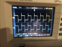
the input to X201/X202 is OK the output (collector ) X203/X204 has the overshoot- the transistors are 2sc1775- which are generally good- I will replace them with KSC 1845 and see if that makes a difference- all the voltages measure correct
the input to X201/X202 is OK the output (collector ) X203/X204 has the overshoot- the transistors are 2sc1775- which are generally good- I will replace them with KSC 1845 and see if that makes a difference- all the voltages measure correct
Attachments
correction- X203/X204 are 2SC1775 and X201/X202 are 2SA872- so I will replace with KSC1845 and KSA 992 respectively
@aparatusonitus- do you mean change +ve and -ve lead for the scope connectors at the speaker output?
Yes.
thanks @as_audio- not a property that seems all that appealing- though I suspect there is not a quick "fix"? Although the amp plays music, I cant believe this is not having an adverse affect?
I will replace them with KSC 1845 and see if that makes a difference- all the voltages measure correct
Don't bother, the problem is the tone circuit topology, and this is normal operation.
I cant believe this is not having an adverse affect?
It's certainly bad if you have a peaky phono cartridge, or tweeter.
Last edited:
so as this is a "feature" of the circuit (as opposed to a bug)- is there an explanation as to why it does this?- I looked at the tone circuits of Onkyo A7, Pioneer SX and a couple of other contemporary designs, and they have a third transistor in their designs- any suggestions as to where I could read more about this?
as always thanks for your help
as always thanks for your help
Am I correct in thinking these are configured as a darlington pair?
It's a common emitter feeding another common emitter.
The first transistor is a PNP type, so it's upside down (emitter to positive rail).
The feedback from the tone circuit goes back to the input PNP emitter
(through a coupling capacitor), as usual.
If you simulate that mess, subbing an op amp for the two transistors,
you'll see that there's still a HF peak, due to the chosen component values.
If the tone circuit had all symmetric component values for boost and cut,
there'd be no peak, since the two composite tone circuit impedances
(output to wiper, wiper to ground) would be equal, giving a gain of x2,
independent of frequency when both of the controls are centered.
But they aren't symmetric, hence the glitch.
Last edited:
Re post 2 and 9 :
do not even think about shorting the speaker outputs by using the
probe/scope ground connected to the red or positive speaker output.
do not even think about shorting the speaker outputs by using the
probe/scope ground connected to the red or positive speaker output.
- Home
- Amplifiers
- Solid State
- JVC JA S22 squarewave overshoot