I will sell various sockets for radio tubes ceramics - carbolite
I will sell various sockets for radio tubes ceramics - carbolite
payment paypal
possible exchange for radio tubes
1) 11pin relay panels 24 pieces used for $1 each
2)
3) LOCTAL panels (4P1L\7N7\EBL21)
ceramics in a cage with metal ears 4 pieces used for $2 each
carbolite in a cage with metal ears 1 used 2 new $6 all
carbolite with metal bracket Germany new 2 pieces $3 all
ceramics lamellas 8 new 2 used $15 all
4)
5) Panels ceramics GU50\GU15
5 pieces ceramics 1carbolite $7 all
6)
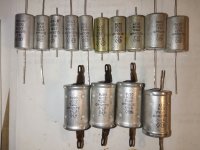
Caps 8 pieces from TVS
Caps 5 pieces closed 6f5\ef37\6j7
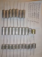
Caps 36 pieces open various 6f5\ef37\6j7
10$ all
7)
Caps 807 tube carbolite\plastic 6 pieces 6$ all
Caps 811 tube open 6 pieces 8$ all
8)
panel 845\211 lamp ceramics 15$
Panels ceramics for 813\4E27\6A6\gu13
RCA UT-104 new 12$
JOHNSON 237 used 10$
6с33с panels thick crimping 2 closed one open 15$piece
good quality
9)
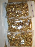
octal 8pin panels ceramics
round panels with good contacts 25pieces used -100$ all
10)
octal 8pin panels made of textolite
22 panels new and used 25$ all
11)
LOCTAL 9pin panels (EF50\EF54)
thick ceramics with British ears 2pieces used
ceramics with ears 3 pieces 160 UAH used
solid ceramics 1 piece used
30$ all
panels 5pin AKORN (957\955\954)
ceramics 8 pieces 15$ all
12)
Panels for RV12P2000 used 3 pieces -10$ piece
panel for RV12D60 1 piece -10$
Panels for Y8 EL11\EL12\EF12 carbolite
7 pieces round Germany -8$ piece
3 pieces oval Germany -8$ piece one glu
13)
panels g807\56 UX5
used textolite panels использованные 3 pieces $2 piece
carbolite panels used 1 piece $2
solid ceramic panels with ears used 1 piece $8
ceramic panels without rings used 3 pieces $6 all
panels 2A3 carbolite UX4 without rings 2 pieces $4 all
panels 6A6\53\310A carbolite UX6 without rings 2 pieces $6 all
14)
panels for GK-71
carbolite collet 3 pieces $15 all
textolite paired panel with holders $8
15)
panel 12s3s\LD1 one with screen $10 pair
Panels for spider AL4\EL3\AF7 carbolite
new 8 pieces -40$ all
soldered 1pc -3$
soldered 1pc adapter EL3\EL6-> 6L6 -3$
Germany original for 3 ears used 2pcs 20$ pair
16)
octal 8pin panels made of carbolite with a nut
black panels mount nut 10pcs - 2$ each
octal 8pin panels made of carbolite with ears Germany
12pcs B\U and new -50$ all
17)
octal 8pin panels made of carbolite with ears
23 panels used - 2$ each
18)
octal 8pin panels made of black carbolite
with metal clip and ears used - 19pcs 2$ each
with metal clip and ears used collet 1pc -10$
mounting panel USA used 1 piece 5$
19)
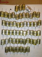
Octal 8-pin panels made of brown carbolite with metal ears
in a metal clip 20 pieces used 4$ each
20)
Octal 8pin panels made of carbolite
under a bracket with two screws - without a bracket used
good quality contacts 12 pieces 6$ all
collet carbolite panel with crimping 1 piece 10$
collet ceramic panel with crimping 1 piece 10$
2A3 panel ceramic new gold 30$ pair


payment paypal
possible exchange for radio tubes
1) 11pin relay panels 24 pieces used for $1 each
2)
3) LOCTAL panels (4P1L\7N7\EBL21)
ceramics in a cage with metal ears 4 pieces used for $2 each
carbolite in a cage with metal ears 1 used 2 new $6 all
carbolite with metal bracket Germany new 2 pieces $3 all
ceramics lamellas 8 new 2 used $15 all
4)
5) Panels ceramics GU50\GU15
5 pieces ceramics 1carbolite $7 all
6)
Caps 8 pieces from TVS
Caps 5 pieces closed 6f5\ef37\6j7
Caps 36 pieces open various 6f5\ef37\6j7
10$ all
7)
Caps 807 tube carbolite\plastic 6 pieces 6$ all
Caps 811 tube open 6 pieces 8$ all
8)
panel 845\211 lamp ceramics 15$
Panels ceramics for 813\4E27\6A6\gu13
RCA UT-104 new 12$
JOHNSON 237 used 10$
6с33с panels thick crimping 2 closed one open 15$piece
good quality
9)
octal 8pin panels ceramics
round panels with good contacts 25pieces used -100$ all
10)
octal 8pin panels made of textolite
22 panels new and used 25$ all
11)
LOCTAL 9pin panels (EF50\EF54)
thick ceramics with British ears 2pieces used
ceramics with ears 3 pieces 160 UAH used
solid ceramics 1 piece used
30$ all
panels 5pin AKORN (957\955\954)
ceramics 8 pieces 15$ all
12)
Panels for RV12P2000 used 3 pieces -10$ piece
panel for RV12D60 1 piece -10$
Panels for Y8 EL11\EL12\EF12 carbolite
7 pieces round Germany -8$ piece
3 pieces oval Germany -8$ piece one glu
13)
panels g807\56 UX5
used textolite panels использованные 3 pieces $2 piece
carbolite panels used 1 piece $2
solid ceramic panels with ears used 1 piece $8
ceramic panels without rings used 3 pieces $6 all
panels 2A3 carbolite UX4 without rings 2 pieces $4 all
panels 6A6\53\310A carbolite UX6 without rings 2 pieces $6 all
14)
panels for GK-71
carbolite collet 3 pieces $15 all
textolite paired panel with holders $8
15)
panel 12s3s\LD1 one with screen $10 pair
Panels for spider AL4\EL3\AF7 carbolite
new 8 pieces -40$ all
soldered 1pc -3$
soldered 1pc adapter EL3\EL6-> 6L6 -3$
Germany original for 3 ears used 2pcs 20$ pair
16)
octal 8pin panels made of carbolite with a nut
black panels mount nut 10pcs - 2$ each
octal 8pin panels made of carbolite with ears Germany
12pcs B\U and new -50$ all
17)
octal 8pin panels made of carbolite with ears
23 panels used - 2$ each
18)
octal 8pin panels made of black carbolite
with metal clip and ears used - 19pcs 2$ each
with metal clip and ears used collet 1pc -10$
mounting panel USA used 1 piece 5$
19)
Octal 8-pin panels made of brown carbolite with metal ears
in a metal clip 20 pieces used 4$ each
20)
Octal 8pin panels made of carbolite
under a bracket with two screws - without a bracket used
good quality contacts 12 pieces 6$ all
collet carbolite panel with crimping 1 piece 10$
collet ceramic panel with crimping 1 piece 10$
2A3 panel ceramic new gold 30$ pair