Dual TK 12 cartridge holder

I just picked up a Dual 1019, while checking it out I found the cartridge holder siliconed to the tonearm shell mount the ear is broken off, I ordered a holder TK 12 from a ebay seller bestaudio, as I had read that the other ebay sellers holder is not great, bestaudios does not have the relief cut for the release arm, so I will have to modify with a die grinder. caveat emptor! I still have to clean and lube, looking @ putting a Nagaoka mp110, Grado Blue 3 or a Ortofon 2M red cart on it, the Shure Realistic R1000EDT will get an after market stylus for 78s.

best compression driver/horn combo for 700Hz-20kHz

hello,
i'm building a medium sized PA and im looking for the best compression driver/horn combo, to play everything above 700Hz (probably 1.4"). i'm aiming for 60x40 coverage angle, so heres the options i found while researching:

horn:

RCF HF64

eminence H14EA

SB Audience H280

P-Audio PH-305

compression drivers: (i know theres some really nice coax compression drivers, but i'd like the price for the comp to be max 300€)

SB Audience Bianco 75-CD-T

FAITAL HF140/ HF1440

18Sound ND1460

BMS, B&C...


i think the horns will all sound similar, im more worried about the compression drivers.... anyone have experience with the ones listed above? or am i missing any? which one is best (max ~300€ )??

cheers, lisette

Hello All!

Hi there, Philippe From Montreal here.
Built a pair of full range speakers last summer using Audio Nirvana 10" ferrites.
Driving them with a very old SIMA integrated from 1994 that needs recapping.
Ordered the parts to build a tube 6BQ5 SE amp.
Have been reading a lot since the last 2 months about tube amps and would like to thank all of you for your contribution to this site; it is very informative.

Have a question about tube amp cooling but am not sure in which topic to post it. mind if I do it here?

Am thinking about using small fans to cool my amp. I currently have 1.5" fans I'd like to mount on the back panel of the amp, left side. Under the mains transformer. They are 12v fans, but I'd run them on 5v or 6.3v to keep the noise down. Would let the air from the fans exit through holes surrounding the tubes, which would be mounted on the front right side of the amp. The flowing air would carry the heat from the inside of the casing out through the holes surround the tube sockets, which would the help control the tube temperature by creating air circulation around them.

Do you think the fans would induce electromagnetic hum in the audio circuits, which would mainly be routed on the right side of the amp, away from the fans, mains, heater wiring, and HV, which would be mostly on the left side?

power switch desperation

Hi friends
I'm—again—struggling with details and aesthetics. This time it's the switch.
Bathing in the sea of variations @ mouser, Distrelec etc., but there's nothing I really like.
I'll probably end up with a switch without "frontend"—requiring a self-made toggle of sorts, but still haven't decided on the function: Push-button, rocker-switch, rotary?

My fantasies are:
- Oversized "long stroke" pushbutton — inexistent?
- Rockerswitch: making a part of the frontplate the switch...
- rotary: Is there a switch that triggers 90°, that could be rotated endlessly? (not back and forth, but on-off-on-off-on etc. in one direction...

Could I get some directions, parts, techniques?
many thanks!
david

Woodworker but first speaker, Kirishima? Other?

My room is 16' by 43' so pretty large, but I would be mostly sitting only 10-12 feet away from the speakers. I've never built a speaker cabinet before, but had looked a lot at the frugal horn stuff like 5 years ago. I have no issue with cutting weird angles and stuff since I have been woodworking for over a decade. I like the Kirishima plans from frugal horn. Is there a full range driver priced like the FE206En or other enclosures I should look at? Thanks!

Transistor noise assessment

Hi all, I don't often visit here unless I need something😱. Thank goodness for the depth and breadth of our membership and their expertise, not to mention their patience.

I looked around for practical suggestions and projects on the topic but haven't found much here on the forum, other than theoretical discussion of design, rather than actual device noise problems. We are facing, if not already struggling, with a shrinking supply of genuine new production, reliable to specified quality, thru-hole semis for the more critical areas in low signal and line-level audio. At affordable prices/quantities, we are left with only a few complementary types, such as KSC1845/A992, BC550/560, 546/556 that meet most of our needs but for how long and at what prices in the future?

On the other hand, we are swamped with cheap copies, fakes and even some good BJTs too, out there but many are what I'd call popular types from 40 or more years ago - good enough for many general applications but doubtful and variable quality for audio. So what I'd like, is a simple amplifier that is set up for a direct audio test of small signal transistors, with a test socket, small loudspeaker on a baffle and maybe another socket for a DMM with bargraph scale to aid recording the results, as necessary.

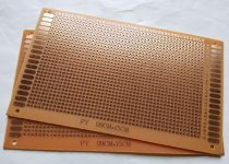
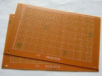
We can do that pretty easily, even on a breadboard but for a more permanent arrangement, I hope to use FR4 matrix board and use the DUT like a buffer amplifier before an opamp, followed by a a small chipamp or perhaps just a low-power chipamp for both, such as LM386, TDA2822, TDA2030 and so on.

The question is; in what circuit, with what input arrangement, impedance, gain, bias etc. do we operate the transistor? It has to give a reasonable representation of how the transistor will sound in a typically sensitive application and that means, I think, the dominant popcorn and hiss noise of the input stage transistor, as a LTP or singleton.

I recently watched a video where a DIY had adapted his unstably high gain stomp-box amplifier and fitted it with a socket for the DUT - no circuit details. He was plugging and testing transistors at a great rate, with very obvious differences between individual, new transistors from apparently, the same lot. I was convinced that there would be useful results with this simple technique if applied to audio amplifiers too, given that many of us are tempted to use cheap semis and this test at least tells us just how bad the idea probably was

I'm really only interested here in qualitative testing because it goes without saying that it's quite appropriate for audio, with respect to SNR. Any support, suggestions for the test circuit, comments etc?

Aleph 5 IRFP244 mosfets cold as ice

Hey to everyone.

I burned all my mosfets when putting amp on heatsink without isolating tape. So i replaced my irfp244 mosfets and turned on the amp, and when i try to play some music the sound is not like a class amp. So i desoldered my irfp9610 and measured they are also dead. I solder new ones and try to play music again and its a little better than before but not good at all. And the mosfets irfp244 are cold as ice after 20min of running time. Maybe any ideas what can be wrong?

Bipolar full range dips but no peaks?

This is my first post so I am expecting someone to point out that I have already blundered.... but here goes:

I think I understand that destructive interference occurs in the mid frequencies as a result of bipolar speaker configuration. I remember reading something Planet_10 said: that constructive interference is less likely to occur than destructive: that dips are more common than peaks with this set-up, and that dips in the frequency response are less noticeable than are peaks.
Is this correct? And if so, why is it the case? I would assume that the interference would occur in equal proportions.
I also read that a lenticular baffle could help minimize this consequence of bipole design, and that a baffle which is wider than the distance between the drivers helps improve response by moving the band in which the comb-filtering occurs.
Can anyone dispel any of these misconceptions, or otherwise guide me toward the appropriate reading material? I would love to read about bipole speakers!
Thank you diyaudio community!

Cyrus Two, shorted, need advice

Greetings,


a couple of months ago I made a great found in the attic of my parents house. A cyrus two issue 07 and two mission loudspeakers. Asking my dad who they belong to, he told me he hasnt turned them on in twenty years and he was happy I wanted to make use of them again.
After a couple of test runs and a new alps blue poty(information received in this great forum), I had the system up and running pretty nicely.

Unfortunatly I wouldnt be writing this thread, if everything was still working fine. After having some friends visit for a weekend and using the system intensivly in the living room. When I moved the speakers back to my room, not thinking straight i plugged both sides of the output cable into ground of the right speaker...
I shorted the circuit. Just had the look at the amp. The upper fuse FS2 is blown, i am guessing thats F3.15A. Didnt see any other anomalies on the critical transistors and components of the protection circuit.


I'm not sure wether I should just replace the fuse and hope for the rest to be intact or if I have to take further percautions to make sure I dont break anything else when putting in a new fuse.
In the first case, where can I get an adequate replacement fuse?


Hoping for advice from some more experienced base addicts. :nod:

Classe DR not turning on (grounding)

Hi guys,
Some time ago I've bought a classe DR10 that needed some TLC (mostly recap), haven't listened to it and just dropped it off at a service shop, they found out the amp wouldn't engage(soft start section does work) unless it was linked to another component, otherwise it was missing ground connection.
He has somehow fixed it but we are still puzzled - how, why? 😕 I thought about the bridge mode switch but he told me that's not the reason.
He inspected the board and found no missing wires or wires dangling loose. We have a 2-wire 230V installation.

Is this something common with old Classe's?

Turntable speed stabilty

This is a new thread that has been spun off from here http://www.diyaudio.com/forums/analogue-source/303389-mechanical-resonance-mms-32.html#post5115798 to discuss the measurement, analysis and interpretation of turntable platter speed and stability, with the end goal of understanding it more and the fixes for it when needed. The Dr Feickert test records and apps have made measurements a lot more accessible, but the presentation and analysis part has been missing. For example Fremer always posts Feickert output on his reviews (e.g. https://www.analogplanet.com/content/technics-direct-drive-sl-1200g-turntable) but you can see that they heavily filter the measurement, throwing away a lot of useful information (and the reviewer wouldn't know what to do with that information anyway).

Member Luckythedog has taken this up a couple of notches by plotting the speed on a polar chart, so you can see speed variation on a rotation by rotation basis. This immediately gives useful additional information you can use to work out where the speed changes might be coming from.

I should cover on this post why this all matters, after all we are talking subsonic effects in the most case. The reason it matters, along with record eccentricity and cart-arm resonances is that you are frequency modulating the wanted signal. Unless you are chasing a 'phat' analog sound this is something that it's worth trying to minimise.

Floor open for discussion

New amp?

I just got a pair of ATC SCM40's very cheap but they lack power.
I'm using bridge Anaview AMS-0100 to run my other speakers, and i'm extremly happy about the sound! If it was possible I would use a pair of brigde AMS-1000, but since Anaview don't make the amps any longer this is not posible.

I would like at least 1000w of power, so far i'm happy with my Anaview and also my 3E audio 3255 but I need more power- What do you recommend me to look after?

Best regards
Johan the noob 🙂

Elektor PA300

nel progetto di elektor del PA300 tra il piedino 5 ed 8 di IC1 viene collegato un condensatore da 33p denominato C9. qualcuno mi sa dire il motivo di questa scelta circuitale? vorrei realizzare il progetto sostituendo NE5534 con un OPA627 oppure con un OPA604 in quanto per le mie orecchie NE5534 è troppo freddo in termini di resa sonora. un grazie in anticipo a chi risponderà a questa mia domanda. ciao allego il circuito elettrico

in the draft elektor of PA300 between the leg 5 and 8 of IC1 it is connected to a capacitor 33p called C9. someone can tell me why this circuit choice? I would like to implement the project by replacing NE5534 with OPA627 or with a OPA604 as for my NE5534 ears is too cold in terms of sound. thanks in advance to those who will respond to my question. Hello Enclose the electrical circuit

Attachments

  • 11.png
    11.png
    735.9 KB · Views: 1,282

Refurbish an Adcom or Build AB100 or Honey Badger

Here is the decision I am facing and would appreciate your collective wisdom.
My speakers will be a two-way system with a horn tweeter and a 15 inch woofer in a vented box. The horn will be driven by a Pass DIY (First Watt) F5. A separate amp will be used for the woofer. The woofer is only about 92 dB efficient and will need more wattage (100 - 200 Watts).

My choices are narrowing on the woofer amp.
1) Use an Adcom GFA-555 ii amp (at least 25 years old & stashed in a closet). I would spend about $100-200 refreshing the capacitors (especially the big ones in the power supply). The amp is old but it is working. The bias is fine, there is negligible DC offset, but there are some on/off thumps and noises. So it is a working amplifier showing some signs of age, but I have always loved the way it sounds, especially in the bass regions.

2) Use an old case/heatsinks from a gutted Adcom GFA-545 (stashed in the garage) and build a Pass "AB100"

3) Use an old case/heatsinks from a gutted Adcom GFA-545 (stashed in the garage) and build a Honey Badger.

The costs are all close enough to one another (with some scrounging on the transformer and power supply parts). So cost is not a deciding factor.

Are there any other choices? Note: tubes are out, chip amps are out, anything less than about 100Watts is out, the power requirement also probably prevent any reasonable Class A amps. Also, I am a cheap son of a gun and also an avid DIYer that likes to learn a bit in the process (I have some experience with electronic projects). I am interested in your comments.

Thanks in advance,
-Tom

Help understand a few cassette deck adjustments/calibration steps

Hi guys,

some time ago i bought this Onkyo TA-2600 3-head cassette deck.
I'm in the process of adjusting it according to the service manual.
Attached is the page with the adjustments (please right-click > open in an new tab for full image view).

The adjustments consist of 8 steps to be executed with that order (1 to 8).
I have successfully completed steps 1 to 4. I'm stuck with some terminology and questions about steps 5 to 8...

Step 5. Bias Trap
In the "Test Tape" column it says METAL TAPE, i guess it means to use a blank metal tape for this test. However in the "Line Input" column there is no input suggested at all.
So, how should this step be completed? Just put a blank metal tape in there and hit the RECORD button then proceed with the adjustment?
If so, where the Input Level control knob of the deck should be set to?

Step 6. HX-PRO
In "Remarks" column it states: "R-467 R-468 counter clock wise" (those are potentiometers on the circuit board)
I don't get it, should those potentiometers turned all the way to the left (counterclockwise) before the adjustment begins?

Step 7. Bias current
In the last column of this test, called "Remarks" it mentions "Input VR Maximum" . What does that mean? Is it related to the Input Level control knob?

Step 8. Record level
Here i guess i need to feed the RCA inputs of the deck with 1KHz sine wave signal and begin with the adjustment.
But in column "Test tape" it does not mention anything. Shouldn't I record the signal to a tape in order to compare Record and PB levels?
Also, again in column "Remarks" , it says "Input VR maximum" which i don't know where it is referring to...

Any help ?

Attachments

  • Adjustments_TA-2600.jpg
    Adjustments_TA-2600.jpg
    425.1 KB · Views: 293

Crown DC300A IOC Lights on W/ Audible Distortion

Hello everyone! I am a first time poster, but have been appreciating this forum's knowledge and information for sometime.


I have a problem with my Crown DC300A amp. The IOC lights have started to come on when I have the channel set to twelve o'clock or higher. When initially turned on, the audio is audibly very distorted, but then becomes less distorted with time. It never fully goes away and IOC lights continue to flicker with the audio.


Before, the IOC lights would come on only if I was feeding audio to the amp while I powered it off. I understand this behavior is normal? It also did not have audible distortion before on power up at all. It immediately sounded correct and the IOC lights did not come on. I have had the amp for about 5 years.


Does anyone have any suggestions on how to start repairing it? I have a little experience with minor repair, but if it is really involved, I might send it out. Thanks!

Cyrus One

hey guys!

i just got my hands on a spoilt cyrus one int amp. from what i've checked, the output transistors have given up. the originals are buv28, but i cant seem to get them from my local retailers. i have been considering getting the BD711 to take its place, with alittle more current and power dissipation abilities i think it would be better off.

i only face one problem, i did try swapping in a pair of 3055s and the played for about a minute before resigning to the grave. i suspect the HFE is too high thus drawing too much current. i was hoping to lower the Iq but there isnt a pot to do that.

i intend to replace the lower resistor in the vbe multiplier with a 1k pot to see how it goes.

is this sensible?

another thing, i was thinking of scrapping the original supply altogether for a psx-lookalike. from what i gather, all i need to do is remove the fuses that connect the original psu to the output devices and add another one. the question here is what voltage does the supply have to be? the markings on the PCB say +/-40v, but the buv28 would not be able to that kinda trashing especially with the increased current that can be drawn with the new supply.

there are holes in the pcb for a larger output device. can anyone help me out in locating a device that would be able to take that added power or would the bd711s do.

thanks a million!

heat management in abs enclosure

I stuffed an old, cheap ebay dac in an ABS Hammond enclosure and noticed the area above the LM7805 heatsink became rather warm.

With a non-contact thermometer it reached 40C while a thermocouple on the heatsink reached 67C after 45 minutes and stayed there. With the lid off, the heatsink dropped to 60C so it doesn't seem like the PSU is suffering due to lack of ventilation.

There's about 15mm between the top of the heatsink and the lid.

Is this too hot for the ABS? It looks like the molding temp of ABS is 40-80C so I'm wondering if the ABS might begin to deform.

Attachments

  • IMG_2358.jpg
    IMG_2358.jpg
    920.3 KB · Views: 155

ICEpower DIY modules 50asx2, 125asx2, 300ac, 700asc2

(UPDATE pricing & quantities 4th feb 2019)


Limited quantities of the following: new, unused, and guaranteed ICEPOWER modules:

50ASX2 SE version = 80$ CAD (+/- 62$ USD or 54 EUR) (qty available: 16)

125ASX2 = 135$ CAD (+/- 105$ USD or 90 EUR) (qty available: 13)

700ASC2 = 450$ CAD (+/- 370$ USD or 320 EUR) (qty available: 2)

1200AS (cables included on that one only) = 480$ CAD (+/- 420$ USD or 365 EUR) (qty available: 1)


300AC = 55$ CAD (+/- 43$ USD or 37 EUR) (qty available: 8)


.::: any order of 500$CAD or more will have 10% discount :::.

.::: any order of 1000$CAD or more will have 15% discount :::.

.::: any order of 3000$CAD or more will have 25% discount :::.


NOTES:

.: Pricing is per module and do not include any cable or chassis or technical support, just the module (except the 1200AS).

.: To be paid in CAD (Canadian dollars) only, either by Paypal or bank wire transfer.

.: Actual shipping fees will be charged (must be shipped with tracking number) and is roughly 25-40$ CAD for continental U.S. per package (can include many modules) and minimum 45$ CAD for anything overseas, including all Europe, Asia and Australia.

.: Canadian buyers will be charged taxes based on their province (contact me for info)

Thank you!
Jon

childhood sub for living room

Hello!

I have a 4 Ohm 12" subwoofer with 200 RMS, 40 Peak ( Rockford Fosgate P212S4 Punch Stage 2 12" 4-ohm subwoofer at Crutchfield )

from years ago and built a beautiful box for my first car out of it. Now I will be home over the holidays and would like to take it out of the attic and put it to use in our home stereo.

So far I have figured out I would be fine as long as I use an amp that can handle 4 ohms. This one even has a crossover built in ( Lepai 2.1 2x40W Amplifier LP-168HA without Power Supply )... so it seems like a good solution. Is the power going to be enough? I'd rather have an amp that can match the 200 RMS of my sub... any suggestions?

Second question is how I connect to my stereo. I could use some line level converters as I did when I had this in the car, but I think it is possible to use the TAPE OUT ? It is an old Panasonic amp from the 70s.

Thank you for the guidance. I'll be home for a month including quarantine and want to make the most of it.

Rotel RX-950-AX

Rotel RX-950-AX wont power on. In standby only

Hello and Happy Thanksgiving
My Partners Rotel won't power on

My business partner and I have been giving each other birthday gifts for 30 years. Needless to say I was running low on ideas. I asked him if he had any wishes and he asked me if I could take a look at his Rotel Rx-950-AX receiver because it had a broken "power on button". To make a long story short after searching the net for two weeks I finally found a DPDT switch that would fit the circuit board and I installed it for him. (it had lost its latching ability). Voila replaceing the switch is was not the problem. It remains in standy.
So far I removed two capacitors located near the transformer c955 and V956.
I have not replaced them yet. I have identified the diode recitifier and some other capacitors of interest 902,903, 905,907. I tested the 902 and 903 with an ESR meter and I believe those caps are good. I can not test 905 or 7 without doing a tremendous about of work removing the board. I was wondering if anyone could give me some testing ideas that might help me isolate the problem better. I hve not tested the diode recitifier yet.
Thank you
I can provide pictures if needed.
Also tried to upload service manual from another site but "size to big"

Thanks Bill

DIY headphone amp - checking my thoughts/calculations

The headphones are AKG 240mkII. 55ohm, 200mW.

Q1. I’ve read that a multiplier is good, is 10x but 2W seems too high?

Q2. Reduction of impedance, using push pull and multiple devices, 110mA max each in an OTL push pull class AB1 configuration.
If I use 4 devices that’s 1/32 = 4* 1/R therefore each tube is 1/4 so 8ohm.

Then using Negative feedback to get from 8 to 4ohms.

Calculate 2W 32ohms sqr(2/32)= 250mA, 32*.25 = 8V peak.
sqr(2/4)= 707mA, 4*.707= 2.829V peak.

Gain 8V/447mV = 17.8971x

But if the impedance dropped to Vout/Vin, or more accurately iirc G/(G+bG) so the gain we actually have into 4ohms is 8/2.829 = x2.82, so we have a ratio we can use to work out the gain we actually need with the NFB in place to be?

I’ve been staring at numbers too much and crap sleep but I think I’m onto the right track?

FS: 6SN7GT/A Tubes

Offering 5 cleaned and tested 6SN7GT/A tubes. All test good on a TV-10D/U military tester. No shorts and all pass tests for gas & leakage. Test results on tubes (minimum conductance for both triode sections = 1650) as shown in photo from left to right:

Tall Tubes (6SN7GT):
Sylvania #1: T1 = 2500, T2 = 2300.
Sylvania #2: T1 = 2100, T2 = 2650.

Shorter tubes (6SN7GTA):
Sylvania: T1 = 2300, T2 = 2100 (tube type number on this one is worn but readable).
GE: T1 = 2600, T2 = 2500.
RCA: T1 = 2500, T2 = 2450.

$40 for all + $6 for First Class USA shipping. Tubes will be individually boxed. Payment via PayPal.

Attachments

  • tested_6SN7gt-a_tubes.png
    tested_6SN7gt-a_tubes.png
    358 KB · Views: 217

Icepower 125asx2 auxiliary power supply fuse

First of all, let me introduce myself, I realize this might not be the correct place to do so, but anyway.

I started after rave reviews tinkering with these modules, I got my hands on one, and it sounded stunning, so I bought a second one t run them in BTL on my system.

Long story short, no pun intended😀, I managed to short out the auxiliary power on both of them, I read all possible threads about these modules in this forum, so I know by now where F300 resides, but it is not clear to me where to acquire a replacement fuse, or alternative for it, has anyone any suggestions?

Rockford Fosgate type RF X2

Working on a RF type X2 with DSP board. Sometimes the amp won't "unmute", but all voltages are there, display is ok, but cannot activate any button at the dsp keyboard. When pulsing the remote (about 10x...?) the amp is working ok.

It is like an other thread i think: https://www.diyaudio.com/forums/car-audio/206160-rockford-type-rf-x2.html was there any solution provided for that problem?

I see at the SG3525 a sync-in signal coming form the DSP board. Only a diagram available for the amplifier /power supply part, not the dsp board...

Maybe some leaky smd capacitors on the DSP board..?

Reverse of the old Loudness Control

Is it posible to make a filter, working off the volume control, which lowers the volume of frequencies below about 55Hz as the volume is turned up. This would allow me to use open baffles with boost on the low frequencies for quieter listening without using subs but If I listened at loud volumes I would turn on the subs and the boost on the open baffles would be reduced. I guess I am looking for a circuit to reduce boost with increasing volume but operated off the volume control so that two separate controls are not needed. This is to reduce xmax at high volumes. Thanks for any help, negative or positive.
jamikl

Looking for a specific PSU capacitor

Hi guys,
An acquaintance of mine is currently recapping my Plinius preamp and we've ran into problems sourcing the 4 main PSU caps.
The info I got from him was: P 16mm, H35mm max, D32mm. 4700uF/63V

I've only found one picture on A'gon but can't make out what caps are these, I suspect Rubycons:
https://ucarecdn.audiogon.com/94c1e...scale_crop/840x630/center/-/quality/lightest/

I haven't seen a cap with 15-16mm lead spacing in this capacity and all are snap-ins. Any ideas? 😕 I don't think the original caps were custom made The preamp has been recapped before but I don't like the way they mounted the new caps - horizontally, zip tied and with wires going to the PCB.

small sealed sub

I currently have the Dayton 8" reference sub in their sealed enclosure and am thinking of adding a second sub. I really like the sound of the dayton and even with just a 100 watt amp it goes plenty loud for my music listening levels.
I don't have enough room to add a second of the same and I've read that it isn't good to mix sealed and vented subs. Is there a problem mixing different sealed subs? I was looking at either LS10-44, or W8-2282 in a small sealed enclosure.

Altec Peerless 1940's TL-217B 6L6/807 PP Output Transformers

From Altec's famed 'Hollywood' era, here is a wonderful example of a very rare and sought-after tube output transformer from the late 1940's. Used in various Altec power amplifiers with push-pull output stages comprised of a pair of 6L6's or 807's.

Original published specifications:
Altec TL-217B Output Transformer (Same as TL-217A, except with 12" long leads)
Max Operating Level: +35dB / 19W (ref 6mW)
Frequency Response: FLAT within 1dB from 20Hz-20kHz!
6.6 kOhm center-tapped primary, Max primary current 65mA, current unbalance should not exceed 7mA
10 & 20 ohm secondary taps
3 ½” x 3 5/8” x 4 1/8” (approximately 8.9cm x 9.2cm x 10.5cm)
Approximately 6 lbs / 2.75kG

This item was purchased at the estate sale of a locally renown amplifier technician and Altec fanatic in his 90's. His license plate read "ALTEC' for over 30 years. He was a certified Altec tech going back to the 1950's, and had quite a bit of Hollywood-era equipment, including a pair of Altec A-324 amplifiers. This transformer was purchased in a plastic bag marked "TL217B - 324 Spare" and matches resistance measurements of other TL-217 transformers. That information, along with the matching dimensions, weight, and number of primary and secondary windings gives me very very high confidence in the origin and model of this vintage transformer.

Resistance measurements made with a Fluke 115 multi-meter. Resistances are consistent with measurements made of two other fully functional TL-217 transformers.

Primary
Black to Brown: 264 Ohms
Brown to Brown: 133 Ohms
Brown to Black: 132 Ohms

Secondary
Black to Yellow: 1 Ohms
Black to Grey: 1.1 Ohms
Grey to Yellow: .6 Ohms

From any primary wire to any secondary wire, resistance measures over 1megOhm, showing insulation no shorts between primary and secondary windings.

Guaranteed as-described. PM me if interested.

Beware - cheap prototype pcb

I recently bought some cheap Chinese prototyping pcbs from eBay and thought I should pass on a little warning. They smell like the old Radio Shack boards while soldering but a few hours later I tried going to bed but found my nose completely clogged. It was so bad I woke myself up coughing. The next day my nose was still clogged but a decongestant cleared it up. I've been soldering for over 30 years and never had any reaction like that before. The remaining boards went right into the trash. Here is what they look like.

Attachments

  • s-l1600.jpg
    s-l1600.jpg
    362.5 KB · Views: 259
  • s-l1600 (1).jpg
    s-l1600 (1).jpg
    312.9 KB · Views: 256

FS: Honey Badger Populated Boards & PSU Caps

I have a pair of Honey Badger boards that I put together. I used it for a few weeks before eventually having a thermal runaway problem. I was told that it simply was not possible with this design and I'm not able to troubleshoot it myself.

Nothing smoked but it got quite hot before I shut it off. I don't know if any parts got damaged.

Whoever buys it needs to be able to troubleshoot. I haven't tried to use it since having a problem.

I will also include 12 Panasonic 8200uF caps, and a DIY Audio soft start and DC protection circuit. This was all bought new in 2014.

$170 US shipping included anywhere in North America. Everything is sold as-is.

DSC07571.jpg


DSC07572.jpg


DSC07577.jpg


DSC07574.jpg

Radian 475 BE PB 8 ohm , 1" compression horn drivers w/ Beryllium Diaphragm , o

Hi
SOLD a pair of Radian 475 drivers with Beryllium Diaphragm .
i bought these to be used in a project that never manifested , time to make some space .
these drivers are brand new , just some handling .

asking $900 ,

i cover shipping at my asking price , you cover paypal .

i also have a pair of seos 18 horns in black i could sell with them .


2960541-71c03c97-radian-475-be-pb-8-ohm-one-pair.jpg


2960544-1f2f7e1f-radian-475-be-pb-8-ohm-one-pair.jpg

another cosyne synergy speaker build

With the extra time at home, I'm working on a pair of bwaslo's cosyne speakers.
I'm following the "cosyne" design literally.

My goal was to have a fun carpentry challenge that results in great sounding speakers. I was planning to make some horn speakers and then these synergy designs started popping up in my searches! WAF will be an issue eventually but I decided to go ahead even if it means these stay in the workshop.

Step 1 is to build the horns without a cabinet but ultimately, I want to have a full range setup with these. Either with full range enclosures or in combo with a tapped horn bass/sub.

I'll post pictures of the build - I have done a fair bit of challenging carpentry in the past so designs like this are fun to ponder and work out on the table saw.

I started out collecting information. it took a while to discover Bill's site...
Liberty Instruments Home Page
and also took time to discover that many of my questions from reading the pdf were answered in the accompanying spreadsheet.

I don't have experience with hornresp or any other modeling software. It looks like a fun rabbit hole but I have other rabbit holes I'm already in that I need to stay focused on.

I tracked down the "bulk buy" drivers easily enough, or so I thought.
P-E has the Gento ($1.25/ea in bulk!) So I bought 9 of them.
I then found the Aura Sound drivers on Ebay for cheap but after they shipped, I realized these were the 4 ohm versions.

Luckily, I found a "kit" of the Cosyne drivers here in the swapmeet section. So I'll end up with extra Gento drivers and an extra set of 4 ohm Aura woofers to either return or use elsewhere.

Vendetta Research SCP-2A

looking for a scheme - please give

kuly-s@rambler.ru

VENDETTA RESEARCH SCP-2A

tell me what transistors are their name

I found one on the Internet - but it does not fit - it is different in the photo there is a second chip in this circuit there is no chip

Attachments

  • scp-2a-0.jpg
    scp-2a-0.jpg
    307.5 KB · Views: 1,799
  • Vendetta.jpg
    Vendetta.jpg
    349 KB · Views: 1,749
  • Снимок.JPG
    Снимок.JPG
    157.6 KB · Views: 1,759
  • fewf.JPG
    fewf.JPG
    192 KB · Views: 1,675

Drivers for Ariel speakers

Hey guys,


I want to build a tl line and first tough of building a Thor Speaker but reading about the Ariels changed my mind.
The problem with ariel is that,as most of you know, the Vifa drivers are no longer available.
I've been reading online for replacements and found the following 3 drivers :

1. SB Acoustics SBMFC30-8
SB Acoustics SB15MFC30-8 5" Poly Cone Woofer

2.Peerless NE149W-08
Peerless by Tymphany NE149W-08 5-1/4" Fiber Cone Woofer Speaker 8 Ohm

3.Seas ER15RLY
SEAS Prestige ER15RLY (H1455) 5.5" Reed Paper Cone Woofer

I have no idea which one actually sounds better. That's why i need your expertise. Which one would you go for?

This looks entertaining!

I've been having a lurk around and decided to dive in. Mostly I like to play with ham radio (KL5A) and have a couple old Heathkits waiting for some restoration, but now that I have a grandson who is tech oriented I thought it might be fun to build some DIY electronics and see if I can get that squiirel running in his head. Right now I'm thinking I'd like to find a simple hollow state amp suitable for breadboarding that was can build together, like the ones I dabbled in as a young teen and mostly didn't electrocute myself with.
Cheers from NoMi!

Aleph 5 - How to demonstrate it is "Single ended"

Hi Guys,

I've been reading information on Aleph amplifiers for months and I would like to build an aleph 5 because it has some characteristics in its design that I consider quite important for a good amplifier such as: class a, single ended, few stages, use of mosfets.

But a person who should help me to build my aleph told me that alephs are not single ended amplifiers because there is no capacitor at the output.

Could you help me to demonstrate that aleph 5 design is a single ended topology? And why hasn't it got a capacitor at the output?

Thank you

Musical fidelity A120 A200, how to DIY increase bias current (more CLASS A)

Hello,
please find attached A200 schematic.

Musical Fidelity A200 - Audiomaniacy

I own Musical Fidelily A120 which has more or less same schamatic as A200.

As you may know Class A is limited to a few watts beyond which (A1, A100, A120) switch to class AB.

Which component should I have to change and trim to SAFELY increase the bias for a wider class A range?

Actually is shown 300mV on 0.47 ohm, that is 0.64A only! :down:
Definetively not a 40+40W Class A as declared.

Do I need a volume control / audio level meter on an AMP

Hello, friends!

Can you give a hint on these question?
- Do I need a volume control on the AMP? My father tells me that I do not need it on the amp because I plan to use the external audio card of the PC as the sound source, and it has it's own volume control. This is in fact true.
Will the volume control somehow deteriorate sound quality? I am looking at potentiometers of ALPS, TKD, Elma. Can you recomment any?
- I would like to have an audio level meter for both channels on the amp. I think they look nice. Something like Audio Level VU Meter WF1029X. Do they work fine in the amp? any particular model you can recommend bellow 50 EUR?

Thank you!

Signal tubes that works decently also at low volatges

Good morning everyone, in the ambitious and maybe even silly attempt to extract blood from turnips ... I need some advice.
It happened in my hands dumped by a friend who buys cheap things and then throws them away (me 😱) a little preamp working with 12VDC with an internal a step-up dc dc converter to generate the anodes voltages.
The original tubes are Chinese 6N3s.
It works 😱 but I have some doubts about the sound quality 🙄
Looking inside I saw that it has a high voltage of only 100VDC I think the anodic one ... in absolute terms very low compared to the usual and recommended 200-250VDC.
Through another friend I learned of the existence of converter sockets with bottom 6N3 and different tops that allow the use of a very huge variety of double triodes such as those of the 6922 family or of the 12au7/12bh7 family.
The question is ... is there a tube that works particularly well even when supplied with voltages this low ?
I would be willing to try it without much pretense with its relative socket converter. For example ... at low voltages a 12bh7 may be a better choice than a 6N3 or would the differences in sound be minimal in the end?
Let's say that these devices have introduced me to the sound of the tubes that I am starting to rather like, even if only for a hybrid system with a solid state power amp.
In general, this preamp already makes the sound more relaxed, fluid but with a good overall transparency. It is a little lacking in the highs and above all in drive ... in the sense that if i put a Toto track with a lot of drumming the drums do not come out from the speakers like i would. Probably it is a matter of not so low Zout ? i do not know. I have not been able to recover the schematic unfortunately. But i am willing to try in the next days.
Surely it is not used at its best as a working point ...
in perspective next year I intend to devote myself with more commitment to a valve pre-line solution that can be quite definitive. For some weeks at least 😀
Thanks to all and again have a nice day,
gino

Attachments

  • preamp douk.jpg
    preamp douk.jpg
    104.7 KB · Views: 316
  • douk from the top.jpg
    douk from the top.jpg
    780.6 KB · Views: 317
  • douk from the side.jpg
    douk from the side.jpg
    631.5 KB · Views: 315
  • douk voltages.jpg
    douk voltages.jpg
    594.8 KB · Views: 303

How amplifier thermal shutdown sounds like?

Yesterday i tested a fake tda2050 ic into heavy load(4ohm) and with absolute maximum supply voltage(+/-25vDC). During bass transients it mutes itself for 1sec or so(repeatedly). I never thought that this counterfeit IC has such a good thermal protection circuitry inside! wow! 😱 😱 😱

Edit:-maybe it was SOA protection circuitry, i don't know.

Midtop Horn

Hello community,


because i have a lot of time these days, i started to build my new PA.
Because it is fully horn loaded, i need a midtop playing from 200hz, i was looking for plans the last days but i couldnt find anything... Is anyone here knowing some Horntops? Most likely i would use 10" and 1,4", the 18sound 10m600 is looking great for me.


I found DDS Horns, Design Direct Sound, DDS, fiberglass horns, horn lenses, fiberglass lenses, line array, waveguide, waveguides, asymetric, community, tweeter horns, mid-range, speaker lenses, speaker horns but there are few information on the website and i have no idea if they send to Germany. Anyone maybe having experience with them?

Would it be possible for a beginner to calculate such a horn on its own? What program should i use then?


Thanks alot for help

Can somebody help me get Windows sound back?1

Dear Anyone.

Mods, feel free to move this, I'm a noob, didn't know where to put it (anatomical suggestions will be considered....!)

I've got Windows XP 64 bit. I used that because I've got 32-bit XP software I love using that HATES Windows 7 Emulation mode, it just smiles at you and crashes in that! Thing IS - I can't get my High Definition Audio Codec working.

Now on my old Windows hard drive it comes up as IDT High Definition Audio Codec, but it got automatically installed when I bought the computer and I don't have an installation disc, it would've been 32-bit anyway. On my Windows 7 disc, which the software hates, it says it's using Realtek. On my Windows XP 64 bit disc (3 separate discs, I just take 'em out of the tower and put 'em in again!) there's just an exclamation mark by it. I've tried no end of downloaded driver installation packages, mainly by Realtek cos I can't find many IDT ones to try, and it just tells me it can't find any hardware, or the hardware isn't working. I know the hardware's fine because it works like a dream on my Windows 7 drive, which I'm using right now!

At one point I had an installer that said I had to have at LEAST SP 1 installed on my XP 64 bit drive. So I found SP2 (remember the 'at least!) and installed that, tried to instally the High Definition Audio Codec again and it STILL said I had to have SP1 at least installed - it wasn't picking up that I'd just installed SP2. Yes, I'd restarted the computer.

That left me absolutely out of ideas. I've got a Foxconn 2ADA mobo with a sandybridge processor, if that helps anyone, and 6gig. of RAM, which was the main reason for 64 bit XP, so I could use it all.

If anyone's got any ideas how I could get noise out of my 64-bit XP drive, they'd have my eternal gratitude. Right now, I'm a disabled composer who can't compose - which, according to those who listen to my stuff, might well be a bonus but sure is frustrating to me personally!

Re. the SP1 thing - I couldn't find a copy of SP1, just SP2. Would SP1 have stuff in it that's missing from SP2, would that be the reason the installation software didn't recognise it? I've zero idea on that front, just vaguely guessing. Last question on the above.

The mobo's PCIe slots for soundcards. Would ANY PCIe soundcard be OK, or are there differences between 32-64 bit soundcards? I've tried googling 'Soundcards that work with XP 64-bit' and only get a short list of cards costing several hundreds of pounds (OUCH!!). But I've seen much more reasonably priced PCIe cards (like, £30) but have no idea if they'd work with 64 bit or not and the vendors don't seem too sure either.

Sorry for all the questions, just stumped.

Yours hopefully

Chris.

Info capacitor Harrison 32C PSU

Hi, need some advice of 4 large caps in the PSU.
I need replacement but not sure which part to get.
The 4 big caps (32000uF 50V surge -10+75%) are aluminium electrolyte's (I Guess) and are located just behind the transformer Output, see schema :
PSU schema | martijnveulemans | Flickr

here another photo :
PSU Caps Harrison | martijnveulemans | Flickr

Can I replace them with this one :
Blocked

Thanks!

+/- 18V Low Noise Fast Transient Supply???

Hello friends,

I need your expert help and guidance to point me in the right direction. I need a super low noise and fast transient response +/- 18V power supply for my phono preamp, but I am having a hard time finding any. I would be happy to buy it or build one from a kit (or at least a circuit board), but I don't have the expertise to design it myself (not from scratch anyway). Could someone please point me to a product or project or something to start from?

Input: 120V 60Hz
Output: +/- 18V (about 0.3A)
Speed and ultra-low output impedance over a broad bandwidth (ideally 3mOhm up to 100KHz)

I would appreciate any help. Thank you!

Testing a VTVM?

I obtained a free Simpson AC VTVM a few years ago. As I recall, it was completely dead - no light or anything. Tube complement is 2 12AT7s and a 6C4. On examination, it seems its only problem was the selenium half-wave rectifier went open. I replaced that with a 1N4007. The 6C4 also does not light up, but I will sub another tube to check that. Possible the 6C4 does not show a lot of glow - the 12AT7s glow fine.

Assuming it works now, how do I test it? Then if it works, how to calibrate? There's no adjustment to speak of other than the meter adjust screw on the front of the meter.

Kicker KXA400.4

Hello, can someone identify these parts in a Kicker KXA400.4? They look like inductors but I don't know for sure, and I don't know the value. I haven't gotten the amp yet but I would like to add some of these to an order I will be placing tomorrow. Also, if anyone can tell me what this amp uses for PS FETs and output transistors along with any know commonly replaced parts for this model. Thanks.

Attachments

  • IMG-20201106-WA0007__01.jpg
    IMG-20201106-WA0007__01.jpg
    410.7 KB · Views: 120
  • IMG-20201106-WA0007__01__01.jpg
    IMG-20201106-WA0007__01__01.jpg
    25.8 KB · Views: 96

Visaton FRS8-8 Enclosure Design Help

Hello,
I have a pair of visaton FRS8 8 ohm, i need a home/enclosure for and I am having problems even getting going on the project as online enclosure calculators i have tried have issues with is specked Qts of 1.04.

All i am looking to make is a pair of small desktop/pc speakers; can someone help me with a bit of a design help please?

Even just the unported volume or ported volume plus dia/length, would be a major help. The rest i think i could figure for myself 🙂

Many thanks in advance imk

WAW Push-push vs TMM

I’ve been playing with a Vifa TG9 supported by a pair of 8 ohm SB13PFCs for the last few weeks.
First: pushing it...
My initial thought was that the SBs, being a budget speaker, could do with the distortion reduction that push-push affords, so knocked up a couple of 20L test boxes, the woofers coupled together with a piece of pine with a thin strip of neoprene on the ends.
The initial xover was simple, a 33uF cap on the TC9, and a .68mH inductor for the SBs.
The sound was a bit wooly in the upper mids, so the next step was to add another .68 inductor in series with the rear woofer, which makes it a 2.5 way. Much clearer sound, and I omitted the pine coupler – too fiddly to get it in, didn’t seem to make any difference, but I don’t listen at high volume. Somewhere, I have an RTA sweep which shows two dips in the Freq. Response, the usual floor bounce dip, as well as a second from the reflected sound of the rear woofer, but it didn’t seem that noticable. Can’t bother dragging that computer out to retrieve it.

Attachments

  • PP1.jpg
    PP1.jpg
    156.7 KB · Views: 193

Does anybody have any info About this french amp?

Hi,
A few years ago I bought a "Concertone 200" on german ebay. It was listed as rare but not working but I liked the look of it and wanted to refurbish it. I blindly disassembled it and then I moved to another town and didnt see it until today. I searched the internet for infos and the only thing I can find is a french thread and a german site called radiomuseum but theres alomst no info at all about this am. I know its from 1986 and was quite expensive back in the day. I would love to make it work again but I'm afraight it will be very hard or even impossible for me without a service manual or someone who knows this amp. So if anyone has infos on this I'd be very happy!!
Thank you!
Projects by fanatics, for fanatics
Get answers and advice for everyone wanting to learn the art of audio.
Join the Community
507,797
Members
7,888,846
Messages

Filter

Forum Statistics

Threads
406,261
Messages
7,888,846
Members
507,797
Latest member
Moza