With the extra time at home, I'm working on a pair of bwaslo's cosyne speakers.
I'm following the "cosyne" design literally.
My goal was to have a fun carpentry challenge that results in great sounding speakers. I was planning to make some horn speakers and then these synergy designs started popping up in my searches! WAF will be an issue eventually but I decided to go ahead even if it means these stay in the workshop.
Step 1 is to build the horns without a cabinet but ultimately, I want to have a full range setup with these. Either with full range enclosures or in combo with a tapped horn bass/sub.
I'll post pictures of the build - I have done a fair bit of challenging carpentry in the past so designs like this are fun to ponder and work out on the table saw.
I started out collecting information. it took a while to discover Bill's site...
Liberty Instruments Home Page
and also took time to discover that many of my questions from reading the pdf were answered in the accompanying spreadsheet.
I don't have experience with hornresp or any other modeling software. It looks like a fun rabbit hole but I have other rabbit holes I'm already in that I need to stay focused on.
I tracked down the "bulk buy" drivers easily enough, or so I thought.
P-E has the Gento ($1.25/ea in bulk!) So I bought 9 of them.
I then found the Aura Sound drivers on Ebay for cheap but after they shipped, I realized these were the 4 ohm versions.
Luckily, I found a "kit" of the Cosyne drivers here in the swapmeet section. So I'll end up with extra Gento drivers and an extra set of 4 ohm Aura woofers to either return or use elsewhere.
Here are some questions...
1. The crossover design doesn't detail the types of components. I figured out that the smaller inductors are 18GA air core jentzen's, the bigger value one is a solid core 18GA (I'm guessing that's for cost). The caps are 5% 250V Dayton polypropylene.
but I'm not sure about the resistors - are these "non-inductive" or are they wires resistors?
2. How finicky is the resistor choice? for example, there's a 6ohm resistor in the crossover but the closest value in PE is a 6.2ohm. (I could build the value up with a couple 3ohm resistors.)
3. I read somewhere that someone using the Gento drivers felt they needed to test each driver out and pick the best ones. I will end up with extras so I'd like to know what sort of test I should do (is it simply testing DC ohms?)
4. I will end up with a set of 4 ohm Aura Sound drivers. I could return them but if they turn out to be great to extend the bass, maybe I should make use of them - in a separate enclosure? Any suggestions on this?
5. How does board thickness affect driver placement? with a 1/4" more board, do the midranges have to be countersunk accordingly into the driver board to preserve geometry?
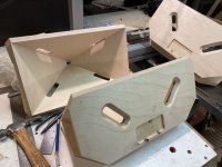
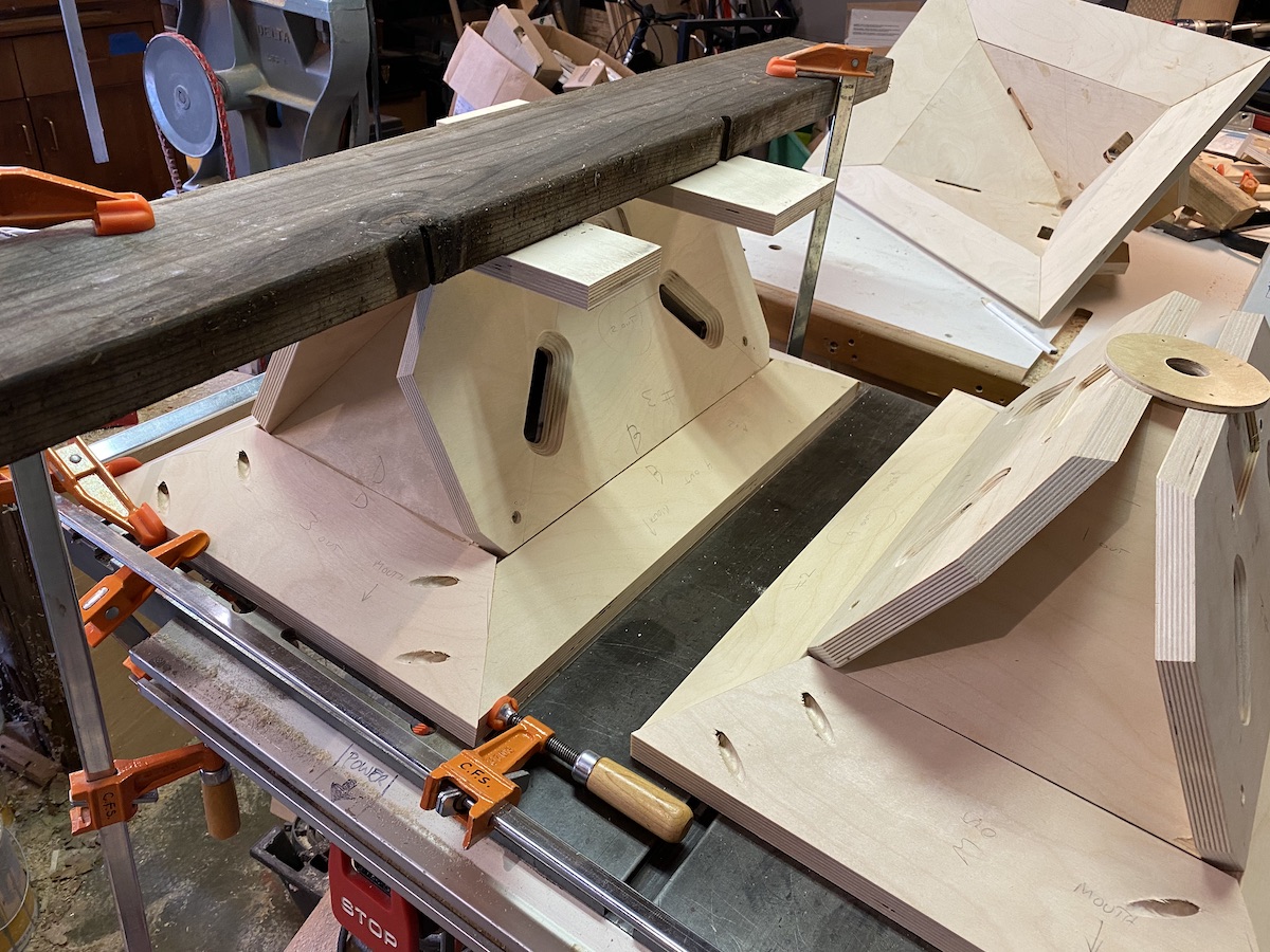
I found the scraps from the panel cuts were really useful for creating clamping jigs. Following Bill's recommendation, I'm building 3 horns. I have one marked as the "seconds" horn - it is using the test-cut pieces and is the first through each step of the pipeline. Once clamped with glue, I have been tacking them together with a brad nailer but being careful to keep the brads away from where the driver ports will go. I set the brad nailer up so the heads remain proud of the wood. So I can pull them out if they are in the way.
Once I have the drivers fitted, I'll add wood screws for added security.

Once I have the drivers fitted, I'll add wood screws for added security.
2. How finicky is the resistor choice? for example, there's a 6ohm resistor in the crossover but the closest value in PE is a 6.2ohm. (I could build the value up with a couple 3ohm resistors.)
Oops - that was a cap, not a resistor. The question then is...
should I go with the 6.2uF cap or go with two 3uF caps in parallel?
Thanks - it's the other way around though. The crossover calls for a 6uF cap but the closest P-E has is 6.2uF.
3. I read somewhere that someone using the Gento drivers felt they needed to test each driver out and pick the best ones. I will end up with extras so I'd like to know what sort of test I should do (is it simply testing DC ohms?)
5. How does board thickness affect driver placement? with a 1/4" more board, do the midranges have to be countersunk accordingly into the driver board to preserve geometry?
A good way to test drivers other than just listening to them in free air to see if they sound obviously broken is to run an impedance measurement. If there are any significant bumps that would indicate a possible issue.
If you change the board thickness then you need to make sure that the volume and shape of the throat chamber is the same as the design as well as making the port the same length and diameter.
Oops.Thanks - it's the other way around though. The crossover calls for a 6uF cap but the closest P-E has is 6.2uF.
Yes, in that case I would parallel a 5.6uF with a .33uF or a pair of .22uF depending on what I had on hand. Technically 6.2 is still within a 5% tolerance of 6.0 which is a pretty common tolerance (even among audiophile capacitors) but I personally would still try for as close to 6.0 as is reasonable.
I wouldn't worry about the difference between 6 and 6.2uF myself. If only driver characteristic values were anywhere near 5%!
And I'd not mess with the board thickness, though. The length of the midrange ports are pretty fussy if I remember correctly.
And I'd not mess with the board thickness, though. The length of the midrange ports are pretty fussy if I remember correctly.
Ok, great! I'll mill down the surfaces where the mids will mate to it.
Also, I noticed in some pictures, the ports were only in the #2 panels while in others, they were centered on the joint between #1 and #2.
On later versions, I noticed the bass port slots look like they were longer than what I see diagrammed in the documentation.
Also, I noticed in some pictures, the ports were only in the #2 panels while in others, they were centered on the joint between #1 and #2.
On later versions, I noticed the bass port slots look like they were longer than what I see diagrammed in the documentation.
The ones with the mid ports placed in the joints didn't work very well, possibly because it pushed the ports out further from the tweeter (?). Go with the ports on the #2. A heck of a lot easier to do, too.
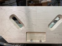
Getting further - bass ports are routed and the mid recesses are done (I’m using 3/4” ply so this is to compensate)
In some of Bill’s pictures, there’s a router ring where the bass drivers go - is that where the suspension surround would touch?
Also, I assume there’s no other criteria for aligning a driver over a port than just making a good seal.
Next is to drill the mid ports - I had some setbacks with the templates I was building so these are lagging behind.
Attachments
I’m going to have to start planning what the enclosure will look like.
I noticed the Danley speakers often port the bass back into the horn close to the mouth. Has anyone tried that with the cosyne or does that only work with a deeper horn design?
I noticed the Danley speakers often port the bass back into the horn close to the mouth. Has anyone tried that with the cosyne or does that only work with a deeper horn design?
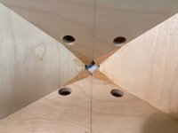
got the mid ports mostly done. I'll likely do some additional shaping when it's time for the finish sanding.
Also, decided to add birch wedges at the CD entrance to make it slightly rounder (octagonal).


(In case you're wondering, the messy spots on the edge of the mid recess are where I had sunk brad nails - I wasn't able to pull them so I used a worn out bit to drill them out prior to using a good router bit on the wood)
Also, decided to add birch wedges at the CD entrance to make it slightly rounder (octagonal).
(In case you're wondering, the messy spots on the edge of the mid recess are where I had sunk brad nails - I wasn't able to pull them so I used a worn out bit to drill them out prior to using a good router bit on the wood)
Attachments
Last edited:
Earlier today, I came across an older and very detailed thread by bwaslo on hificircuit.com. It answers some of my questions but also introduces new ones...
DIY Synergy/Unity spreadsheet | HiFiCircuit
Someone therein had noticed a discrepancy in a cap value in the crossover design. The mid driver high pass cap is labeled as 18uF but the P-E part number next to it is for a 15uF cap.
And to answer one of my first questions - wire wound resistors are fine for the crossover (non-inductive isn't necessary)
Wow - this is a real challenging project. I can get really precise with normal cabinetry but I find with this that getting that perfect joint is illusive. Tiny errors multiply quickly! I will have to cut thin filler strips of hardwood to wedge into some of the gaps.

Attachments

I'm researching designs for the low end of the system and so far, am considering a TH Spud inspired design.
If I were to make the more compact "Tony's Cab" enclosure for these speakers, what low end cut off should I plan for?
If I were to make the more compact "Tony's Cab" enclosure for these speakers, what low end cut off should I plan for?
Wow - this is a real challenging project. I can get really precise with normal cabinetry but I find with this that getting that perfect joint is illusive. Tiny errors multiply quickly! I will have to cut thin filler strips of hardwood to wedge into some of the gaps.
Agreed about errors adding up. But don't underestimate the capability of wood filler putty!
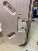
I have been test fitting drivers. the cone drivers are straight forward but the CD is giving me trouble. The Celestion has blind threaded holes facing the horn flange. I had assumed incorrectly that the CD housing would have through holes - that would have allowed me to put long screws through the driver housing into the flange.
I can align the driver so that two of the screw holes are accessible - I would be able to fit socket cap screws in there between the mid drivers. would two screws be enough?
A more complicated option would be to remove the wood flange and make a wider aluminum flange that is first bolted to the driver and then bolted to the back of the horn.
- Home
- Loudspeakers
- Multi-Way
- another cosyne synergy speaker build