Rotel RX-950-AX wont power on. In standby only
Hello and Happy Thanksgiving
My Partners Rotel won't power on
My business partner and I have been giving each other birthday gifts for 30 years. Needless to say I was running low on ideas. I asked him if he had any wishes and he asked me if I could take a look at his Rotel Rx-950-AX receiver because it had a broken "power on button". To make a long story short after searching the net for two weeks I finally found a DPDT switch that would fit the circuit board and I installed it for him. (it had lost its latching ability). Voila replaceing the switch is was not the problem. It remains in standy.
So far I removed two capacitors located near the transformer c955 and V956.
I have not replaced them yet. I have identified the diode recitifier and some other capacitors of interest 902,903, 905,907. I tested the 902 and 903 with an ESR meter and I believe those caps are good. I can not test 905 or 7 without doing a tremendous about of work removing the board. I was wondering if anyone could give me some testing ideas that might help me isolate the problem better. I hve not tested the diode recitifier yet.
Thank you
I can provide pictures if needed.
Also tried to upload service manual from another site but "size to big"
Thanks Bill
Last edited:
Have you checked to make sure you have proper supply voltages? If not do that first, because it will more than likely tell you they are fine and it is protection not stand-by issue.
If it is protection, most likely you have DC on the speaker outputs and have a shorted output transistor and maybe a driver transistor.
First is to verify you have all voltages you should, then move to the harder stuff to find the issue.
If it is protection, most likely you have DC on the speaker outputs and have a shorted output transistor and maybe a driver transistor.
First is to verify you have all voltages you should, then move to the harder stuff to find the issue.
Thank you for those quick and thoughtful ideas bullitstang. Could you step me through that if I could get the service manual to you. I have all the equiptment but my know how is lacking.
I would post the manual and schematic on the forum.
I can certainly help but there are others that will jump in that are way more knowledgeable than me. It also will assist those that might have the same issue in the future.
I can certainly help but there are others that will jump in that are way more knowledgeable than me. It also will assist those that might have the same issue in the future.
Rotel RX-950-AX wont power on. In standby only
Thank you.
I reduced the PDF so I can upload
I am pretty good at locating things and have a rudimentary understanding of diagrams but this unit looks complicated to me.
Thank you.
I reduced the PDF so I can upload
I am pretty good at locating things and have a rudimentary understanding of diagrams but this unit looks complicated to me.
Attachments
Last edited:
Maybe start with uploading the power supply, any schematic diagrams and amp board as separate individual PDFs.
As it is it’s of very little use.
As it is it’s of very little use.
Rotel RX-950-AX wont power on. In standby only
I apologize. I am off to a bad start with the schematic upload. I am using a Mac and I cant figure out how to upload a legible diagram. I could give teh other website where I download it from but I dont want to violate site rules.
Tomorrow I will have access to a pc and an adobe program and I can do a better uploading job. thank you and speak soon
Bill
...I could give teh other website where I download ...
It is in HiFi Engine, and we often post those links.
Rotel RX-950 AM/FM Stereo Receiver Manual | HiFi Engine
Rotel RX-950-AX wont power on. In standby only
Thank you for posting the HiFi Engine service manual for me.
I guess my basic question is where do I place my meters electrodes to see if the power supply is putting out correct voltage?
Thank you for posting the HiFi Engine service manual for me.
I guess my basic question is where do I place my meters electrodes to see if the power supply is putting out correct voltage?
as a first check - make sure you can access without chance of shorting the probes.
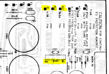
#1 with meter on AC - check AC1 and AC2, with your red and black probes - doesn't matter which way, then do the same for AC3 and AC4. write down the voltages.
#2 Take your black probe and clip to the speaker ground output (black)
With one hand holding the red probe, your other hand out of the way and no jewelry on. Touch the red probe (with meter set to DC) on B+ and B-.
Appears they should give you +/-94Vdc. If that checks out - next it to see if you can verify DC on the outputs.
#3 with unit off - take probes and clip to the speaker outputs (red to red, black to black), with meter on DC, turn the power on to the amplifier and look at your meter.
Shouldn't go over 1-2V and probably less than 1V. Do this test for both speakers (right and left). Trying to verify DC, before the relay protection kicks in, so you will only have about 1-2 second after power up to verify.
Report back on your findings and should give us some clues where to start further diagnosing the amplifier.
Attachments
Understood!
I will report back tonight.
Thank you
Will these results be valid with the fact I popped out c955 and c956?
I will report back tonight.
Thank you
Will these results be valid with the fact I popped out c955 and c956?
Last edited:
Rotel RX-950-AX wont power on. In standby only
I did test AC voltage going to the board
125V
Just reminding this was without those 2 orginal capacitors I removed.
as a first check - make sure you can access without chance of shorting the probes.
#1 with meter on AC - check AC1 and AC2, with your red and black probes - doesn't matter which way, then do the same for AC3 and AC4. write down the voltages.
No voltage
#2 Take your black probe and clip to the speaker ground output (black)
With one hand holding the red probe, your other hand out of the way and no jewelry on. Touch the red probe (with meter set to DC) on B+ and B-.
Appears they should give you +/-94Vdc. If that checks out - next it to see if you can verify DC on the outputs.
No voltage
#3 with unit off - take probes and clip to the speaker outputs (red to red, black to black), with meter on DC, turn the power on to the amplifier and look at your meter.
Shouldn't go over 1-2V and probably less than 1V. Do this test for both speakers (right and left). Trying to verify DC, before the relay protection kicks in, so you will only have about 1-2 second after power up to verify.
No voltage
Report back on your findings and should give us some clues where to start further diagnosing the amplifier.
I did test AC voltage going to the board
125V
Just reminding this was without those 2 orginal capacitors I removed.
I assume that is AC1 AC2, which is good (125 is ~+/-88Vdc) but would help to verify actual DC voltage.
Did you check AC3 AC4? Or DC on the speaker terminals?
Did you check AC3 AC4? Or DC on the speaker terminals?
Rotel RX-950-AX wont power on. In standby only
I checked ac1 and ac2 where you indicated on the diagram you so kindly included as well as ac 3 and 4. There was no current. likewise on what I assume is the recitifier B_B+ also no current. On the terminals no DC current.
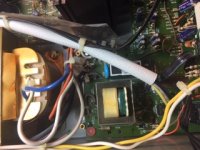
The only place I see voltage is where the power cord attaches to what I am calling the power supply ie the board with two transformers (one large other small). There are 2 Wires entering the large transformer a blue and white and there is no current across them. I also noticed what I think is a brown gound wire and there is 125 from brown to blue and from brown to white.
The transformer is dead silent
I checked ac1 and ac2 where you indicated on the diagram you so kindly included as well as ac 3 and 4. There was no current. likewise on what I assume is the recitifier B_B+ also no current. On the terminals no DC current.
The only place I see voltage is where the power cord attaches to what I am calling the power supply ie the board with two transformers (one large other small). There are 2 Wires entering the large transformer a blue and white and there is no current across them. I also noticed what I think is a brown gound wire and there is 125 from brown to blue and from brown to white.
The transformer is dead silent
With current entering the primary through Brown, white, blue but no current on ac3 /ac4 or ac1 or 2 could I have a blown transformer?
I have a question. There are 2 locations for the ac1 and the ac2 as well as 2 locations for ac3 and 4. The location you showed me on the diagram has no voltage. Just above the small transfor on the power board there is another ac1 and ac2 and this one has current. ac1 ac2 98 v.
I measured the resistance between ac1 on the power board to ac1 on main board and it was infinity. Are these two ac1 in the same circuit?
Last edited:
Rotel RX-950-AX wont power on. In standby only (update)
as a first check - make sure you can access without chance of shorting the probes.
#1 with meter on AC - check AC1 and AC2, with your red and black probes - doesn't matter which way, then do the same for AC3 and AC4. write down the voltages.
Update on this test: For my previous performance of this I tested the voltage putting my probes simulataneously on ac1 and ac2 and also simultaneously on ac3 and ac4. I reported "0" voltage. When I put one probe on ground and the other on any one of these 4 points I get approx 3-5 volts.
#2 Take your black probe and clip to the speaker ground output (black)
With one hand holding the red probe, your other hand out of the way and no jewelry on. Touch the red probe (with meter set to DC) on B+ and B-.
Appears they should give you +/-94Vdc. If that checks out - next it to see if you can verify DC on the outputs.
#3 with unit off - take probes and clip to the speaker outputs (red to red, black to black), with meter on DC, turn the power on to the amplifier and look at your meter.
Shouldn't go over 1-2V and probably less than 1V. Do this test for both speakers (right and left). Trying to verify DC, before the relay protection kicks in, so you will only have about 1-2 second after power up to verify.
Report back on your findings and should give us some clues where to start further diagnosing the amplifier.
Highly unlikely your transformer is blown. Just to confirm, you are sure you have your meter on AC when testing these points?
The only difference in what you have done is split the AC in half, so something is wrong if you get “0”, where full voltage should be and 3-5 volts where 1/2 potential voltage should be?
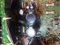
Might be easier if you took some high res pics from a few angles of the power supply board(s), so we see what you see.
The only difference in what you have done is split the AC in half, so something is wrong if you get “0”, where full voltage should be and 3-5 volts where 1/2 potential voltage should be?
Might be easier if you took some high res pics from a few angles of the power supply board(s), so we see what you see.
When testing ac1 for example. One probe goes on ac1 and the other ground.....right?
Last edited:

- Home
- Amplifiers
- Solid State
- Rotel RX-950-AX