AC is between two points, so red in AC1 and black on AC2.
DC is referenced to ground, so black probe on ground and red probe on the point you are testing.
Try again as those measurements do not make sense.
I think you might stop at this point and get professional help. To do this safely you need to understand a DMM, measurements and a basic understanding of AC and DC voltage/current theory.
Do not want you to get hurt because you do any of this incorrectly. This is at your own risk.
Rotel RX-950-AX wont power on. In standby only
AC is between two points, so red in AC1 and black on AC2.
There must be some misunderstanding. You asked me to measure the voltage between AC1 and AC2. From my understanding of the wire diagram (uploaded) AC1 and AC2 share the same line. There is "0" resistance between them. How can I get an AC or DC between these points?
Perhaps this is more of a misunderstanding rather than my ability to understand the basics of a digital meter.
With much respect and appreciation of your efforts
Bll
DC is referenced to ground, so black probe on ground and red probe on the point you are testing.
Try again as those measurements do not make sense.
I think you might stop at this point and get professional help. To do this safely you need to understand a DMM, measurements and a basic understanding of AC and DC voltage/current theory.
Do not want you to get hurt because you do any of this incorrectly. This is at your own risk.

> From my understanding of the wire diagram (uploaded) AC1 and AC2 share the same line.
No. There's lots of wires here. Going somewhere else. Not electrically connected, but the draftsperson opted to *draw* them together to reduce clutter.
> There is "0" resistance between them.
Have you measured? Transformer windings are often less than 1 Ohm and few ohm meters will read such low values correctly.
Draftman schematics for RX-950-ax
Thank you so much for explaining what I am seeing. That make sense to me that the "low ohm winding" along with the "technique" of the draftman to avoid clutter made me conclude all these points were in line when they are not.
Interesting though I only get 5-6 volts on these point which I believe is probably coming from the smaller transformer as a standby voltage.
I recently read an article talking about "standby boards" and how issues within them can deactivate the main transformer for protection (Sony Receiver Amplifier Will Not Start -- Checking Standby Board).
I am wondering if the two bad caps I removed have essentially through a "microprocessor somewhere" have shut off the activation power to my larger transformer.
Last edited:
I do see a smaller transformer on the board next to the big one, so it seems you'll have to continue looking in the standby power supply. If the microprocessor is not getting any voltage or the relay supply (often 12 V) is too feeble as a result of bad caps, the unit won't turn on. That's two voltages to verify. Only if those are nice and stable you'll have to continue looking further (e.g. a bad cap hiding in the microprocessor reset circuit).
Thank you Sgrossklass
That is the assumption I am working on. I removed two caps as I mentioned early in this thread. (c955 and c956) Both tested bad! I have not received new ones yet. They are close to the smaller transformer and the relay which I believe will activate the larger transformer which sends the voltage to those other pins mentioned previously.
I previously reported "0" voltage between points and was told my numbers did not make sense and it was how I was using the meter. I take no offense because it is reasonable to assume that because I am an amateur .....However I believe my number of "0" do make sense based on your observations and comments.
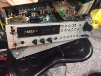
Rotel rx-950-ax Now powers on!
Excuse the pun
So "recapping my problem" My unit would not power up and caps 955 and 956 tested bad. I replaced these. These caps along with small transformer and relay serve to turn on the large transformer ie the unit.
Although a novice/amateur I get the same thrill as the pros...even doing very simple things like replacing a bad cap. I want to thank the members of the forum for their patience and wilingness to teach and even their "protectiveness" of their "DIY students health."
My self, I happen to me a first medical responder and these are very hard times so I really appreciate it when I see people helping people. So again...thank you everyone.
Bill
PS fixing this unit will bring a smile to my partners face who is also a first responder so that makes me double happy
Attachments
So those two caps were the issue and now it’s working?
Great news! Now air back and enjoy the music, again.
Great news! Now air back and enjoy the music, again.
- Home
- Amplifiers
- Solid State
- Rotel RX-950-AX