Germanium PNP transistor based amplifier (OC36)

I've just recently been interested in building some amplifiers, which I've done with modern transistors just fine. But I have this box of much older transistors, all in TO-3 packages, and was curious if I could use of these in a project.

Among them is a handful of OC36 germanium transistors, I've seen some 'vintage' schematics use the OC71 for example. The most interesting is that the OC36 is very similar to the 2N278 in specifications, and the 2N278 is a power transistor made for class A and AB stage amplifiers.

Anyone know if the OC36 could be used in an audio amplifier? Anyone know of schematics based on germanium PNP transistors?

Something along the lines of
An externally hosted image should be here but it was not working when we last tested it.


Thanks

in search of some inspiration ONKEN mood

HI fellows,

I'va this lovely pair of cabinet on a shelf and I need a pair of loudspeaker for garage (not so loud ;-)

I'm not happy with the Mark-Audio in that enclosure.

Any thought about what I can put in? Maybe a small coaxial (but I would prefer a FR)
This is for garage boys, so no intellectual listening session ;-) only boom boom
They must be around 16/17l (outside dim. are 37x28x21cm)
Thanks

Miraculous Germanium Transistors from China

Germanium transistors can be easily found in radio receivers made about 30 years ago. From the first stage through to the last stage, it could be all powered by those tiny tined naughties. Though vulnerable to high voltage and temperature change and notorious for high leakage, they played important role in those old days to transit music into each household, even in remote areas, just like the broadband Internet today.

Their sound is very distinctive from those of silicon solid states, much looser and smoother. Somebody says silicon solid state may suffer from unstable frequency characteristics when being overdriven, while Germaniums will not, just like a tube. That somewhat makes sense (you will know it by listening to the recorded replay posted hereinafter). But Germaniums are usually having poor characteristic frequency and it would be hard to find something beyond 10MHz, partially for at that time the communication system didn’t need too high frequency like today and partially for the era of Germaniums ended too early and too soon.

However, things always have exceptions. Fortunately China has been long embracing Germaniums till late 1990s and for this reason it ever produced Germanium transistors with characteristic frequency up to 4GHz. And those with 100MHz, something typical with an audio silicon solid state, were mass manufactured and can easily be found even today over online stores. And what is more amazing is that they can have high Hfe (relatively to those primitive ones), such as 100 to 200 or even higher and low leakage, such as when Vce=10V, the leakage is smaller than 50uA. This opens an opportunity to build a DC-coupled Germanium-Silicon hybrid preamp with Germaniums used as voltage amplification and output devices, with slew-rate better than conventional Ops, such as AD797 and LME49710/720.

How to handle the low CE voltage ability of Germaniums took me some time to think, and finally I decided to use a Douglas type topology in which the voltage amplification device only needs to bear a single rail’s voltage, for example 10V as I used in this case. The push-pull architecture can contribute another merit by cancelling the Germanium’s leakage noise, yielding better noise performance than those traditional single-ended architectures. What is different to Douglas is that I replaced the first input bipolar pair with a pair of JFETs and removed the coupling electrolytic capacitor on the feedback path to enable real DC-coupling. For output, to save the efforts to calibrate for zero DC output and to protect downstream solid-state power amplifier, I used film output capacitors to block DC output.

Sherwood S3000 III SM

Hello,
I am looking for a SM or schematic for my Sherwood S-3000 III Mono FM tuner.
It's SN is 3229314. It has a SS rectifier, 12AT7, 6BS6, 6CB6A, 3-6AU6'S, 6AU8 & 6BN8 Tube complement.

I have emailed several manual sites including vintagemanuals, other groups to no avail.

If you have one, I am willing to pay or if you know of someone who might have it please let me know.

Thanx - Bob V

Heat effect on crossovers: Energy Veritas 2.4

I recently moved 2 Energy Vertitas 2.4 speakers in a commercial van from MI to CA, now both have no sound output from the woofers. The tweeter on both is working. No external damage to speakers. Could crossovers be affected by excessive heat in van? Any suggestions as to problem and fix? Crossover boards seem to be ok with wiring between but need to be diagnosed.

So strange that both speakers have same problem.

Onken with Beyma 15XA38Nd

Hi, after having a lot of fun with my Beymas in Tannoy GRF style enclosure, I would like to try the Onken... but ofcourse with adapted volume for the Beymas... that would be around 130 to 150 liters...
Does anybody out there have thoughts or maybe experiance with this combination?
All the best!
An externally hosted image should be here but it was not working when we last tested it.

Unexplained low frequency measurement mystery

Unexplained low frequency measurement mystery- Solved

I need some advice.

Over the last year I have made a lot of measurements of different drivers, both in cabinets and in test baffles, as well as complete systems. I use the Omnimic package. Since my focus was on taking measurements for use in simulation and developing passive and active crossovers, I was mostly focused on the regions above 100 Hz.

I always noticed some peaks and nulls below 100 Hz in my measurements, and I always attributed to room modes. But recently I began to take a closer look.

What I found is that I am consistently measuring a deep null at 64-68 Hz, even when it is physically impossible for such a null to exist.

In the first pic you can see the near field responses of 4 different drivers. Black is an SB34NRX75-6 12 inch driver in a 70 liter sealed box. Blue is a SB17CAC35-4 in a 10 liter sealed box. Purple is a SB17MFC35 in a 12 liter sealed box. Green is a Satori MW16TX mounted in an open baffle. All have a pronounced null between 64 Hz and 68 Hz.

There is no reason (that I can think of) for a null to appear like this in a near field measurement. None of the impedance plots show anything going on at 64 Hz, just a typical sealed box driver response. It is just not statistically probable that all four drivers would have some kind of defect at 64 Hz.

Since all of these measurements were made in a room with an 8 ft ceiling, and the half wavelength of 66 Hz is 8.5 feet, I wanted to eliminate that as a possibility, so I moved the woofer and satellite out into the middle of a large room. This room is 32 ft x 23 ft with a vaulted ceiling that transitions from 9 ft to 20 ft. I did near field measurements of the SB34NRX and the SB171CAC35. I won’t bore you with the plots, they were virtually identical to what was measured in the room with the 8 ft ceiling.

I am also showing an ambient noise reading I took in my basement when I had the house fan running. This same microphone / software has no problem picking up 60-70 Hz in RTA mode.

So I decided to take some measurements under conditions where I know that no 64 Hz null should exist. I have the Satori MW16TX mounted in a foam board box, so first I measured the near field response of this driver, and the null was present as expected. Next I cut a small hole in the back of the foam board cabinet and pushed the microphone in. Amazingly the null was still present. I patched up the hole and took the box onto my driveway to conduct a ground plane measurement. I was 14 ft from the nearest wall. Once again, I measured the same null. In the plot, Black is nearfield, Red is taken from inside the box, Blue is outdoor groundplane.

WTF. I am confused. Any ideas would be welcome.

Attachments

  • Pic1.png
    Pic1.png
    102.2 KB · Views: 383
  • ambient-from-inside-box-R1.png
    ambient-from-inside-box-R1.png
    211.6 KB · Views: 379
  • s20201214_113035.jpg
    s20201214_113035.jpg
    263.3 KB · Views: 352
  • s20201214_120249.jpg
    s20201214_120249.jpg
    412 KB · Views: 350
  • s20201214_121635.jpg
    s20201214_121635.jpg
    459.2 KB · Views: 351
  • s20201214_121734.jpg
    s20201214_121734.jpg
    802.7 KB · Views: 169
  • Pic2.png
    Pic2.png
    92.4 KB · Views: 176

Understanding bias setting TSE

Amps is back up and running after C6 bit the dust and in setting everything up I pulled the meters out and spent some time making sure all is set and stable.

I have a few different 5U4G rectifiers and I noticed that the Raytheon has lower B+ voltage the the two RCA's, 248-250 vs. 282-286. In deciding to leave the lower volt rectifier in there I spent some time getting the bias set where it sounded the best. 32mA was the ticket.

If I decide to run one of the higher voltage rectifiers should I reduce bias? Hot hot is too hot? What about tube life?

I believe I understand the principal of bias just looking for the practical. I also have read Georges suggestion of where to bias a 45 amp in Tubes and Applications.

Why does suggested bias go down at higher voltages?

Thanks,
Walt

RCA termination at one end of a Speaker Lead?

Hi Guys.


I have an interesting combination of vintage speakers.


A pair of Minimus 5 Realistic Speakers (which have RCA out for parallel speaker connection).


I also have a pair of wall mounting Realistic speakers which can be hooked up as rear speakers for a mock surround.
They've been set up to include individual volume control so they can be tweaked for optimal sound set up.


Can speaker wire be terminated to RCA type connection at one end?


cheers


Cliff

Understanding System Power supply IC: Help Needed

Understanding System Power supply IC: Help Needed
IC is BA4900 12 pins System power supply for car stereos:

I've pulled apart an old car stereo to troubleshoot why it is not powering on at all.
It doesn't power on in the car or when I connect to a 12v bench power supply.

Goal:I will use it to attempt to convert the cassette connection to an AUX-in for an old Toyota used as a beach car - which will be other threads I start I'm sure.

I'm finding it hard to follow the traces, but I'm currently testing at the IC BA4900 which when googled I get System power supply for car stereos.

Data Sheet:
Link

Using Pin 12 GND for a test point of my black COM cable on my multimeter
I only get readings from pin5(VDD)=5.9v and pin7(VCC)=12.1v
The others show 0.0v
I'm worried that the issue may not be here though and VDD needs to reach a controller which would send a voltage back to the correct pin then other pins would light up if instructed.

Is anyone that is knowledgeable in this able to see anything in the datasheet that would tell you if any of the other pins should be alive even without the a voltage getting to the controller

Pin Votages from the datasheet
1 - VAR output 10v
2 - MODE2 SW 5v
3 - MODE1 SW 5v
4 - Stand by 5v or 0v
5 - VDD output 5.8v
6 - AMP output 1v
7 - VCC - 12v
8 - ANT ouput 1v
9 - COM output 8v
10 - Radio output 8V
11 - FM Output 8V
12 - GND

Thanks in advance.

Where to find tube schematic and footprint models

I am making a new hybrid amp design, and I couldn't seem to find any tube schematic files or footprints.

I don't know if I have been searching in all the wrong places or whatnot.

Specifically I am looking for 6SN7 footprints and or schematics. The footprints are really the most important however.

I am making the design in KiCAD although Eagle would also work because I can convert them.

Is there any big library with all of these?

Thanks.

DIY Line Array Speaker Questions: Impedance, Power Handling and SPL

I'm thinking about build my own line array speakers for live sound.

This is the driver I am considering for the column line array.

The GRS 8FR-8 full-range 8" speaker features a paper cone with poly foam surround. A whizzer cone extends high frequency response and dispersion. Engineered to withstand rigorous commercial use, this driver will also deliver great results when used in point-source hi-fi applications. Affordable pricing makes it perfect for DIY applications. Ideal replacement for the Pioneer B20FU20-51FW (also known in DIY communities as the BOFU)


Product Specifications
Nominal Diameter8"Power Handling (RMS)60 Watts
Power Handling (max)85 WattsImpedance8 ohms
Frequency Response39 to 16,000 HzSensitivity91 dB 1W/1m
Voice Coil Diameter1.5"

I was thinking about putting 4 speaker in each enclosure and wiring the first two and second two in series and connect the the pairs in parallel to a achieve an 8 ohm load.

My questions: The 60 watt RMS rating per speaker concerns me. Will wiring them in series each pair in series and then connecting them in parallel increase their power handling capacity?

The drivers are rated at 91db @ 1watt/1meter. What will the approximate SPL be when all 4 are combined?

I'm thinking this. Four speakers will be moving more than one speaker and they will be sharing the work. Am I correct?

I am also thinking that the power handling should increase but I have no idea by how much.

I plan on powering them with a powered mixer so I'm looking at minimum 300 watts going into a 4 ohm load as there pair of the "Hound Sound" "Whizzers"

One speaker able to go from 39hz to 16,000 is impressive to me. 16,000 is about the limit of most dynamic mics. I'm thinking this would remove the need for subs. I am also thinking of making a column with 8 of these speakers.

Your thoughts?
  • Like
Reactions: DblAA

F6 build problem

I just finished building a set of F6 amp (buffered version, with source degeneration resistor), since I have balanced front ends so I am using a LL1540 transformer to convert the balanced signal to unbalanced following the datasheet and directly connect the output to input of F6

The problem is, almost no sound, or more like the input is shunt to ground. So I did a little debugging.

1. I bypass the transformer and used a signal generator to drive it. It works, sounds alright and the scope gives me nice waveform and a gain around 15db

2. I left the amp power off and drive from transformer input and measured output(still hooked up to input to F6). It still looks fine, with an insertion loss around 0.6db which the transformer specifies as 0.5db.

3. Then I powered the amp on, then, the output from the transformer(input to F6) drops to almost 0. So I redid step 1 with various signal source resistance and calculated a input impedance around 10kohm, less than expected but still looks fine.

So now I am confused, could someone enlighten me what did I do wrong?

Portable build upgrade - recommendations for (cheap) drivers

Hello everyone!
I am planning to upgrade my self made portable "boombox" with some better speakers and amplifier, and i already have quite a good idea on what to get but i'd like some opinions from who wants to help me with some advice 😀

First of all, the box is already built (attached picture). It's a 10 litre bass reflex box with two, let's say full-range, speakers that share the said 10L, and two ports that tune the box to 58Hz IIRC (i made it some years ago). The speakers were salvaged and are just some random "eongchang" 4 inch 5W drivers that came off an AIWA LCX110 microHiFi, so nothing fancy really.

The box already has a 4s li-ion battery, so 14.4V nominal.
For the amplifier i'm gonna use a tpa3116 based aiyima board with tone controls and bluetooth. This means that the maximum power going to the speakers will be around 30 watts at 1% THD+N, plus i'll have some sort of EQ.

As for the drivers, what i'm looking for is a pair of woofers and tweeters, keeping the budget a bit low (possibly less than 100€ for everything, crossover included) but still managing to get a good sounding system. The woofers can be both 4" or 5" and i need a good compromise between sensitivity and bass extension, as the speaker is battery powered.

Speaking of the woofers, my best bet for this enclosure are the Sb Acoustics sb12pfcr25-4, as they have an acceptable 87.5 dB sensitivity and are quite cheap. I've simulated them in Speakerboxlite with my box specifications (so two drivers into a single 10L ported enclosure, Fb being 58Hz) and the frequency response shows an F3 of 57, F6 of 50 and F10 of 44Hz. How do you think that would sound? I personally am new to speaker modelling so i don't know how these numbers translate to actual listening, if these would have good bass or be a bit lacking.
I've also simulated the sb13pfcr25-4 but it looks like the bass would be worse on these in the same box.
I checked some other drivers as well, but the SB12 look to be the best compromise between sensitivity and bass extension.

For the tweeters my possible choice are the LaVoce tn100.70: they're cheap and with a second order crossover (and maybe a 1.5dB L-pad as they're 89dB) they should do well with the SB midwoofers, or at least it looks like so from my simulations with XSiM and the crossover calculator spreadsheet.

I already tried designing the crossover but i'll wait until i decide myself on the components to purchase before asking you further information 🙂

So, in the end this is what i have in mind for now, and i hope to hear some opinions from anyone willing to help in this upgrade project. I hope i didn't violate any forum rules in the post (if so, please let me know!)
Thanks in advance to everyone 🙂

Attachments

  • photo_2020-10-19_20-53-00.jpg
    photo_2020-10-19_20-53-00.jpg
    113.1 KB · Views: 260
  • Annotazione 2020-10-19 211125.png
    Annotazione 2020-10-19 211125.png
    62.9 KB · Views: 257

Antek Power Transformer wiring for the SSE

Hi

I want to use the following transformer for the SSE board, and I am wondering how I should wire it up. Very new to this, and my confusion about the high voltage wires - so wanted to check.

AS-4T360 - 400VA 360V Transformer - AnTek Products Corp

View attachment 900708

My thought is to connect the WHITE and YELLOW wires in the two 360v in to get 720V, and connect the YELLOW(0V) and WHITE(720V) to T1-RED and the same WHITE(0V) to T1-RED-YEL.

View attachment 900712

Is this the right way to think about this?

Thanks
Mark

Interstage transformer coupling

Hello,

Can please someone clarify two things with regards to IST coupling in the following common-cathode configuration.
1. Do I need grid leak here? I've seen various opinions on whether it's better to have IST staring at ~infinite grid or rather have a fixed load of, say, 100k.
2. Do I need a grid stopper here? Or would IST secondary DCR serve the purpose to prevent oscillation/low pass?

Thanks,
Igor.

Attachments

  • IMG_20201217_143027.jpg
    IMG_20201217_143027.jpg
    566.6 KB · Views: 580

An amplifier hum issue

Hi,
Ive just put together an amp / preamp combo. Every thing sounds great but it has an audible hum when the amps input cables are connected to the preamps outs, the hum is not effected with the volume, its a set volume.
The weird thing is if i connect either the left or right channel only via the cable theres no hum?
Its only when both channels are connected.
Anyone got any ideas?
Regards
Mike

Memphis 16-ST500D

Does anyone have any drawings of this amp (old).

I've got it operating but have a hiss in the output.

There are 2 daughterboards on the output. I assume the first is the PWM creator and the second is the final drive?

I have one low side output in and one hi.

Low side is getting hot. If I remove the "PWM" board it does not get hot. However drive looks ok when board is in.

Attachments

  • Old-School-Rare-Vintage-Memphis-16-ST500D-Mono-Amplifier-_1.jpg
    Old-School-Rare-Vintage-Memphis-16-ST500D-Mono-Amplifier-_1.jpg
    23 KB · Views: 162

Altec Lansing VOTT

The A series VOTT bass cab seems very interesting. But is it a bass horn? It looks like a front loaded high-mid horn with a huge reflex cabinet on the back of the driver.
So how does the bass keep up with the midrange? What is the typical cross over frequency?
How does it compare to a Karlson or Karlsonator?
Thanks. I am about to build something for my 15s and the VOTTS are rather large but what the hell... I find it hard to deside which design to go for. High efficiency and dynamics are pri 1.

Need replacement transformer - velodyne sub

Hi, appreciated for help with this... no joy searching internet.

I acquired this sub DOA and through testing, i have figured out the thermal fuse blew in this transformer. I would love to get it going again, but no idea how to get same transformer or at least equiv enough. This has been a learning process for me at each step and appreciated for some inputs from experienced here.

Marked:
Ten Pao
TP76u57E

Much appreciated! Al

Bang @ Olufsen 5500 media server

Thought you guys might appreciate the aesthetics (not to mention the sound quality) of this one.

The components are tightly fitted into a beorecord 5500 housing. The components are:

+ Intel NUC D54250WYK Core i5 4th Gen Windows 10 Pro 120GB SSD 8GB RAM

+ 1080p touch screen

+ 12v 2amp power supply for display

+ 19v 5amp power supply for NUC

+ Firefly Cobalt USB DAC

+ Micro USB to USB and mini HDMI to HDMI cables for display connection (USB for touch control).

+ Custom DIN to firefly audio cable for connecting to the CD input of Beomaster 5500.

DIY Mains conditioning Power bar (Mains DC, and Mains voltage)

I folks,

I'm not looking to open a can of worms on the supposed sonic advantages/disadvantages of mains conditioning.

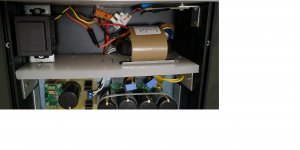
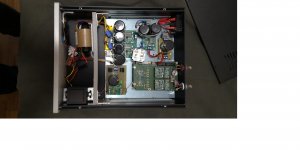
Let me explain the situations: I moved to a new city in the last year, and since getting here every largish transformer I have hums. The toroid in my SS amp hums, an EL I'm using in a new amp hummed a bit when I tested it, I can hear the transformer in my Desktop computer hum, and the power amp for a home theater system hums, and there is now more background noise and a worse power off thump than there was before. These things are all in the same room, but the hum follows any of them around the house.

All of this humming is getting close to driving me insane. We also have a small aquarium pump elsewhere in the house that vibrates, so much so it has kept me awake some nights. I replaced one pump on warranty, thinking it was the pump, and then tried another brand, all of which were well regarded for being quite and smooth. Most of the time it is very quite, but sometimes it is extremely loud, I've noticed when it is being loud the Torioid in my SS amp hums worse. Both of them are loud right now in fact. CFL's seem to hum sometimes too.

My fiance hears the humming too, so I know I haven't just lost my mind. In fact, she though she was going crazy until she mentioned it and I told her I could hear it too.

So from some research I think that there is likely DC on the mains, quite a bit, or that there is some signal at higher than 60hz. Or both. Unfortunately I only have a DMM, so i'm not sure how to test for either of these. However, I'm going to be moving a lot over the next few years, so it occurred to me that I might as well just build something that deals with both.

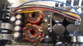
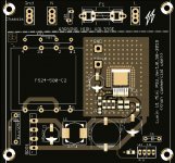
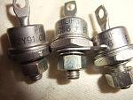
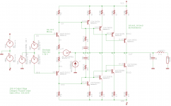
I've found plenty of circuits for DC blockers, seems like some diodes and large capacitors in parallel is the way to go for that.

As for dealing with non-60hz signal that isn't into the RF range, I'm having trouble and looking for suggestions.

Additionally, the mains voltage is not very stable here, and rather high. Normal is 123, but I've seen it as high as 125 and as low as 118 when testing outlets. I've been getting more into vintage gear lately, so I was thinking I might want some a 117 or 115 outlets on my "power station". I may just buy a variac (which would probably hum too :headbash:), but what are some other solutions and ways of dealing with the unstable voltage, usually it will be go +/- 1v a few times a minute, with occasional big drops and spikes that aren't related to local draw.

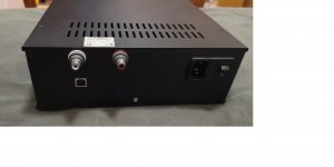
Speaking of testing outlets, I've had to replace a few because of faulty grounds, I was thinking of incorporating some sort of fault detection circuit and indicator LEDs on my power station, any suggestions there as well?

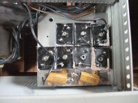
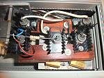
I've got about 4x as many power bars as I actually need around here, so I have plenty of outlets, and appropriately rated switches and breakers to scavenge.

Sorry for the long rambly post- I didn't sleep well last night. Can you guess why?

Marantz 510m: one channel high DC when starting

I'm working on this marantz 510m and in one channel the DC goes really high on startup before stabilizing. It swings positive to around 30V. I'm still running it on the dim bulb tester with a 60W bulb. The other channel doesn't do this. There's no speaker protection, and it pins the meter, so it needs to start up better than this. It takes 20 or so seconds to stabilize. I haven't changed much on this board. The electrolytic caps and the emitter resistors. The outputs have all been changed to onsemis. I've swapped driver boards between channels as they disconnect from the outputs/drivers and the problem follows the driver board.
When it settles it plays fine.

I've never seen something swing this hard when powering up, how can I troubleshoot this?

FS: 5.25" midwoofers Audax HM130Z0, Eton 5-212, Aurum Cantus AC-130F1

I have the following drivers for sale. All were purchased brand new over the last 6 months and used very little.

Audax Aeroget 5.25” HM130Z0, $80/pair, qty 2 available (1 pair SOLD, 2nd pair still available)

Eton 5.25” 5-212/C8/25 HEX Symphony II, $90, qty 1

SOLD ** Aurum Cantus 5.25” AC-130F1, $70/pr, qty 4 ** SOLD

Paypal included in price, shipping at buyers expense. Drivers shipping from Michigan, USA

DCM speaker recommendations for my older Yamaha receiver

Howdy,

I have a circa 1988 Yamaha RX-700 natural sound receiver I purchased brand new in High School. I've been using a pair of vintage Altec Lansing 83 (100 watt, 8 ohm) bookshelf speakers in my 13' by 16' living room. Not great sound, for sure. I'm trying to decide which of two options I should chose, both are used DCM speakers which seem to be highly regarded, especially the TF-600.

But, is my amp too under-powered for the TF-600s? Should I go for the CX-27s instead? Thought I'd ask the experts!

My Yamaha receiver has the following specs:

Power output: 65 watts/channel into 8 ohms stereo
75 watts/channel into 6 ohms
Speaker load impedance: 6 ohms to 16 ohms
frequency response: 20Hz to 20kHz

Option 1:

DCM TimeFrame 600:
recommended amp power: 10 - 250 watts
max power handling: 250 watts RMS peak
6 ohm nominal
frequency response: 30 Hz to 20kHz

or option 2:

DCM CX-27
recommended amp power: 10 watts to 150 watts
max power handling: 150 watts RMS peak program
6 ohms nominal
frequency response: 35Hz to 20kHz

Serial driven parametric equalizer

Good morning,

I'm looking how to achieve parametric EQ driven by serial commands (issued by an Arduino).

I wouldn't like to process the audio in the Arduino because I want it real time and high quality, something that I think, Arduino can't perform.

At this time, I know the TDA7317 for graphical EQ with serial commands but it is not parametric.

I found the LC75281E but didn't found any example schematic and I didn't found where to buy it (discontinued product?)

Is there any chip or DIY kit allowing me to add parametric EQ into my circuit and allow my Arduino to drive it?

Thanks in advance.

Pocket Mic preamp

Hey guys!

My friend got himself a new microphone, a Sennheiser e935.
While he loves that mic, he wants to connect it to his iPhone, or laptop via jack.

I want to build him a preamp, which amplifies the signal coming from his mic to the maximum of the phones/laptops input.. Using batteries.

I was wondering if there is any op amps which I could use with a single 9V battery (Or maybe 2 AA batteries (3V)?)

I have found a schematic on Elliots page (attached)
Do you think this could be enough for this case? (Of course with variable gain [R6 = pot])
How could one limit the maximum voltage output for not destroying the phones mic input?

Thanks for your help
Daniel

Attachments

  • balanced-io-f7.gif
    balanced-io-f7.gif
    3.4 KB · Views: 968

Dodecahedron driver recommendation?

Hi all,

Thinking about build one of these, a 12 faced omni.

First driver that comes to mind is 3FE25,
because I already have 4, and 8 more would only cost me another hundred dollars.

I'd like to get reasonably flat freq response from 100Hz, to as high as possible, without excessive low end boost.

For any of you folks who have contemplated a dodec, any driver recommendations come to mind ?

And did you consider porting them?

thx 🙂

What Is Wrong With This DAC? Measurements of CERMECH CS4398 DAC With NJM4580D

What Is Wrong With This DAC? There is significant distortion and it measures far worse than the LJM CS4398.

Attached Picture: Measurements of CIRMECH CS4398 DAC With NJM4580D.


Does anyone else have this DAC? Has anyone else measured it? FYI: I remeasured my ES9028Q2M to make sure I did not have a problem with my ADC.

Attachments

  • CERMECH CS4398.jpg
    CERMECH CS4398.jpg
    991.6 KB · Views: 244
  • CERMECH CS4398 NJM4580D.png
    CERMECH CS4398 NJM4580D.png
    207.6 KB · Views: 226

Anarchy 7 - Wavecor MTM Crossover

I'm having great results with the Renditions; can listen to them for hours on end and they always make everything sound just a bit more interesting.
That said, wanted to try the Wavecor tweeter version, and at the same time PE started supplying Wavecor.
Well all good, and had plenty of supplies to make a pair of MTM's with front port/BB boxes; similar to the Renditions with the larger Wavecor tweeter.

Now the stumbling block, no xo schematic.

Any ideas folks?


TW030WA11_12
[TWO30WA11-01]
Anarchy 7 inch woofer by Denovo Audio

**Boxes shown, no wires, xo, etc.

Attachments

  • Anarchy 7.jpg
    Anarchy 7.jpg
    194 KB · Views: 942
  • MoreLight.jpg
    MoreLight.jpg
    59.4 KB · Views: 911

FS: Mirand Audio USB DAC V.1 AK4490 DSD direct diy

Closed

For sell euro 600,00 with shipment

MIRAND AUDIO DAC VERS 1. AK4490 V1
Dac Sounds exceptional and it's done as follow: SEE PICTURES
many pmlcaps in dac and shield pcbs.
n. 2 transformers, 1, RCORE 30 W & EI for XMOS separate supply
n. 4 separate supplies respectively for Xmos , Dac, Clock, with ultralow noise regulators, 2 x LT3045 ( Ivanov) , 1 KoSa (LT3042 with pmlcaps ) 2 x Mvralica, one for Raw another for Xmos
all snubberized with Quasimodo.
Modified Ground path.
New Ultra precision Crystal Clock NDK SDA ( the original quartz were " normal")
Please note n. 8 Mundorf Mlytic 10kuF 25 V
Dac SOUNDS DSD Direct (Original PCB can't) with Arduino soldered near Xmos ( see pictures) Arduino is programmed for modifies Xmos firmware.
nextgen rca Output wired with pure silver 24 awg
All AC and DC wire are Neotech UPOCC 18 awg copper wire

Attachments

  • MIRAND V 1.jpg
    MIRAND V 1.jpg
    149.5 KB · Views: 517
  • MIRAND V 2.jpg
    MIRAND V 2.jpg
    171 KB · Views: 517
  • MIRAND V 3.jpg
    MIRAND V 3.jpg
    256.1 KB · Views: 492
  • MIRAND V 4.jpg
    MIRAND V 4.jpg
    681.7 KB · Views: 497
  • MIRAND V 5.jpg
    MIRAND V 5.jpg
    620.3 KB · Views: 478
  • MIRAND V 6.jpg
    MIRAND V 6.jpg
    740.4 KB · Views: 253
  • MIRAND V 7.jpg
    MIRAND V 7.jpg
    382.4 KB · Views: 236
  • MIRAND V 8.jpg
    MIRAND V 8.jpg
    129.2 KB · Views: 218

Using REW for XO with regards to phase

Hey,

I have a couple of questions with regards to phase and doing XO simulations with REW measurements.

Using a calibrated USB mic and the "acoustic timing reference" option turned on in REW - will I be able to accurately use the phase data in the exported FRD file?

If not, then I reckon I can at least use it to measure the time delay between each driver? Like so: Driver time alignment

Soft Start and Standby Functions for your Aleph Amplifier

I compiled differents desings and added my own to create a nice little Soft Start and Standby circuit that can be usefull in building your Aleph.

Here the features:
The circuit is turn on by a main AC switch, possibly on the back of the amp then the softstart activate.
The softstart is the Elliot Project 39 version. A nice feature is that a small rating external switch can be used to turn on/off the amp from the front, it connects instead of a jumper on JP1.

Two nice additions are a safety feature of the soft start, a thermal cut off fuse, that will be mounted between the power resistors. It prevents any catastrophic failure.

The circuit can also power two 12Vdc fans. Their speed can be reduced by adjusting the value of R10. The Fans can be turn on/off automaticly by the standby mode or on continuously using JP2

Then working on the same 24V supply is the standby circuit. It is operated from a front mounted switch/led assembly or by remote 12V trig on the back. It provides these features:
-Auto-reset at start-up, standby mode activated, led inside power-on switch is flashing.
-Two DPDT relays can be used to provide the standby functions. I'm planning to short the inputs and select the lowest channel's bias setting in standby. The JP1 jumper can select the relays state in standby, On or Off.
-Press the SW1 switch, and the amp turn On full bias and ready. The SW1 led turn on continuously.
The momentary switch is well debounced and don't produce any false trigger.
-A 12V remote trigger on the back can activate the power-on mode remotely.
-A 12V alarm relay option. In case on an alarm inside the amp,
an external 12V will activate a rapidly flashing led.

The over-temperature cut off can be implemented using thermostat directly mounted on each channel heatsink, in serie with the main power switch and fuse, just before the soft start PCB. The digikey part number for the cut off is: 317-1085-ND
Thermostat, 75 DegC, Normally-Closed

Attachments

Facebook Users

I created a specific group for amplifier repairmen and those who are seriously learning on Facebook. I'm going to try and get it filled with knowledgeable people and make it a place where someone can ask questions without being made to feel like an idiot for trying.

That being said, anyone who comes in with a blown amp and just says "what's wrong" won't be staying long.

Also hoping to create a directory of repairmen so if you have someone who doesn't want to ship, they can be directed to someone in their area.

Car Audio Amplifier Repairmen

Tweeter suggestion for monitor Satori MW16P

Hi all
Would like to build solid and high quality monitors. Just for every day background listening. I run my main towers when I need higher spl and more bass.

I have heard pretty good about Satori MW16P midrange and decided to use these.
I am openminded what tweeter should be very good match to these midranges.

I prefer tweeter which is:
*price range up to 250usd
*musical
*not fatiguing
*warm
*lively

Some suggest directly TW29DN - but maybe anything else that fits to my criterias?

Midrnage: Satori MW16P Black Egyptian Reed Cone Woofer

Lumin U1 Mini Upgrade power supply

Hi. An other little project of mine. I have a very nice Lumi U1 mini music server. The only real difference between the U1 mini and the full U1 is a less fancy case and the use of a little 12V switching power supply instead of a full discrete one into the bigger U1.

So there is an easy way to reach for the full U1 performance, replace the switching power supply... There are a few commercial offering out there, but they are rather expensive. I made my own little version, that fit into an Hammond enclosure. It uses the same LDO voltage regulator as the Lumin external power supply.

My version use a standard rectifier, or like I will do, use a 'perfect Bridge' active rectifier, then a CLC filter, the the LDO 12V regulator. There is provision on the PCB for an external power on switch and front ON led.

The original Lumin SMPS supply is a 12V, 0.7A. Mine will be limited/protected at 12V, 1A.

There is provision on the board to use a small split core transformer from Triad, simply because I had one in stock, but you can always wire an external toroidal transformer if you wish. No need for anything fancy, any 12V/1A transfo will do. The PCB supports dual primaries 115/230V transfo.

Anyway I'll have a few left over pcb from my prototype. If interested they will be 25U$ each + Shipping + 3%Paypal fees.

I'll test my prototype first, then I'll will confirm the parts list and schematic.

Naturally you will be responsible to install your supply with your own Lumin, and I cannot be responsible for any damage you can do in the process. Thanks for your understanding...
SB

Attachments

  • PCB.JPG
    PCB.JPG
    80.9 KB · Views: 458

Sub Heatsink for 6 Zener Diodes in DO5 Outline for electric isolated Mounting

I am looking for a possibility of isolated mounting of 6 pcs DO-5 zener diodes one the same heat sink.
The diodes looks like this versions:
1N3309B Z- DIODE 10V 50W DO-5 | Capcomp Shop
NTE Elektronik nte5247ak Zener Diode - 6.8v 50w do-5 5% Cathode Case | eBay
Actually there should be heat sinks for it with one surface accordingly TO247 and one surface with a hole of 5mm Ø

The reason for that is the follow:
In a preamp with shunt regulated power supply there must replace high power zener diodes in an electrical isolated outline like that one from this rectifier:
KBPC3510FP pdf, KBPC3510FP description, KBPC3510FP datasheets, KBPC3510FP view ::: ALLDATASHEET :::
go to the first attachment.

The replacement parts of this zeners are only available in an electrical unisolated DO-5 outline, but I want to fix five or six of this electrical unisolated devices of this zeners on the same heatsink (the last image shows only a temporary solution, which I don't like).

Thanks for an advice.

Attachments

  • DSCF5143.jpg
    DSCF5143.jpg
    913.7 KB · Views: 195
  • DSCF6763.jpg
    DSCF6763.jpg
    5.1 KB · Views: 166
  • DSCF6765.jpg
    DSCF6765.jpg
    7 KB · Views: 174

Help needed for unknown SEMELAB Power Zeners "8136 8215E"

I want to know a replacement for the above mentioned zener diodes. I don't know the naming of the associated outline, but it looks similar to those under
VS-GBPC2508W | Vishay VS-GBPC2508W, Bridge Rectifier, 25A 800V, 4-Pin GBPC-W | RS Components
but with only two connectors.
The power zeners (7 pcs) are in use in a voltage regulator for creating the anode voltage of a diy tube pre-amplifier with ECL-86
Thanks for posting a URL for a data sheet.

DIY Line array - Matching AMP power with the RAW speaker

Good morning,

I'm looking to design and build some DIY line array active speakers for small live use (200-300 peoples, indoor).

I think starting with 10 inch raw speakers, and to put two of them on each cabinet, with one compression driver.

But my problem is all raw speakers in my country doesn't have a precise documentation (mostly china stuffs), so I don't know its effective RMS power, effective frequency range, ...

How can I proceed to evaluate the best amplifier circuit power I can use to achieve my need? As we will use it mainly for rock/prog metal, I wish to achieve the maximum quality.

Thanks in advance.

Tian Stability Plot at multiple points across the Output Swing

OK, I think I've made this work. Multiple Tian stability plots across the signal swing. Thanks to jcx and fas42 for assistance.

I have a 250W CFP output stage I'm working on. I wanted to break the CFP local loop to check GM & PM at several points on the output swing, from -80V to +80V. Here's what I did.

Nested .step sweeps:
.param dcin=0 prb=0
.ac dec 100 1 1e9
.step param prb list -1 1 ; Tian loopbreak probe V1 and I1; set prb=0 to turn off probe
.step param dcin list -78 -40 0 40 78 ; run Tian loopbreak at each of these voltages

One .func in the plot.defs file for each of the dcin values:
.func stb1() -1/(1-1/(2*(I(VI)@1*V(OUT)@2-V(OUT)@1*I(VI)@2)+V(OUT)@1+I(VI)@2))

.func stb2() -1/(1-1/(2*(I(VI)@3*V(OUT)@4-V(OUT)@3*I(VI)@4)+V(OUT)@3+I(VI)@4))

.func stb3() -1/(1-1/(2*(I(VI)@5*V(OUT)@6-V(OUT)@5*I(VI)@6)+V(OUT)@5+I(VI)@6))

.func stb4() -1/(1-1/(2*(I(VI)@7*V(OUT)@8-V(OUT)@7*I(VI)@8)+V(OUT)@7+I(VI)@8))

.func stb5() -1/(1-1/(2*(I(VI)@9*V(OUT)@10-V(OUT)@9*I(VI)@10)+V(OUT)@9+I(VI)@10))

I think I'll start a thread on this, so others can see it, cause it's useful.
Here's the schematic and plots for your viewing pleasure:

Attachments

  • OutputStage.png
    OutputStage.png
    25 KB · Views: 157
  • Screen Shot 2015-03-31 at 3.09.40 AM.png
    Screen Shot 2015-03-31 at 3.09.40 AM.png
    364.6 KB · Views: 146

Perfecting loudspeaker design using novel polymer materials

Hello!

New forum member here who is in the process of building my first loudspeaker pair, separate thread regarding the build found here: Studio 3-way reference monitor build, need help choosing drivers

I have been reading a lot on the subject in recent weeks/months and I have been sharing this new found interest with my brother who has responded in kind and now we are 2 really interested persons who would like to really get serious when it comes to loudspeaker design. I am currently studying to become a medical doctor, which is not really applicable to loudspeaker design (if you're not counting human hearing, maybe there is a future for me in studying and advancing our knowledge of human perception of sound?? Any input/thoughts/available paths forward regarding this would be greatly appreciated).

My brother has finished his phd in chemical engineering/material design. His graduating work (not sure what you call this in english speaking countries? Graduate work/project?) was concerned with synthetisizing novel polymers based on a set of wanted characteristics.

We have now developed a vision of using his knowledge/skill to develop new materials for loudspeaker drivers and loudspeaker enclosures, materials tailor-made to the needs of the frequency range in which the driver/enclosure operates.

Imagine a midrange driver that utilizes a tailor-made membrane-material for its specific frequency range which results in perfectly matched characteristics resulting in frequency response linearity and extremely low levels of distortion. Then imagine using this same material for the enclosure for this driver. Then imagine using this same methodology for all drivers in the design of a complete/full range loudspeaker. Maybe there is a possibility of creating something great sounding and economical?? I can specify what (modern) techniques of polymer synthetization we are planning on utilizing if there is an interest in knowing more about the potential of polymer materials.

I would be extremely grateful for all input/ideas/information pertaining to our quest. What is the function of the membrane of a loudspeaker? What is the source of its inherent structural instability (break-up etc.)? How is this instability related to the self-oscillating frequency? How is this related to the molecular make-up of the material? What would be the ideal material characteristics of a membrane for a specific frequency range of a loudspeaker driver?

Any sources (books, links) will be gladly accepted and researched, any insight/input/ideas regarding the topic is extremely welcome!

What would be the ideal loudspeaker membrane/enclosure material? Discuss

audison av12

I have an audison AV12 in a very small, 18l vs 20 reccomended.


heres the TS parameters i pulled w dATS


Re 3.66
fs 39.4
vas 93.09
Qes .74
Qms 3.55
Qts .61
Le 1.47
EBP is 57


Im running about 220w into it in the box and its fat below 100hz to 20 hz in my honda Accord


Thinking of trying it in IB sice according to hornresp i would gain about 13db on the same power and still have excursion to spare.


Can anyone recomend something else? space available is 32"w x 15"h x 16"d gross


Priority is low frequency extension so i dont mind a large box since hoffman says so!


I built the little shoebox so icould get more tha the 6x9s in the rear deck.

Silent fan replacement in ART SLA-1

I have an ART SLA-1 (stereo class AB power amp) and the stock fan is noisy. I want to replace it. I'm not an engineer, but have replaced many noisy fans in computers. Apparently it is a 12v 40mm x 20 mm fan. Should this one work?

Silenx

Here is the original.

Thoughts??

P.S. I just took out the original fan; it's made by Bi-Sonic, and is a DC brushless fan, model SP402012H, operating voltage 12V (10.2 - 13.8), current draw 0.16A; power consumption 1.92w. The Silenx specs are: operating voltage 8-14v; current draw 0.03A; power consumption 0.36w, so that all seems fine. What concerns me is the Bi-Sonic is 7000 RPM with a Flow CFM of 8.53, and the Silenx is 3000RPM with a Flow CFM of 6. I don't drive this amp hard at all, so I don't expect it to ever get that hot; will this "quiet" fan be strong enough??

BBC style thin wall enclosure - how thin can one go?

I am about to order plywood for my speaker project, a subwoofer assisted two way speaker, with BBC-style thin wall enclosure. When researching the subject I found that as far as panel thickness goes Harbeth/Spendor/Rogers (so BBC contractors) used from 8mm in two way monitors to 12 mm plywood for larger boxes.

Now, from my local supply I can order only 7 mm plywood, even though its just 1 mm thinner than BBC spec, its as much as 12,5% difference from 8 mm panels used in commercial designs. So how thin can I go? I know that reducing panel thickness will lower the resonance frequency of the panel, which is a good thing according to BBC's approach, but there has to be some limitation, otherwise people would be using 3-5 mm panels to push the resonance below speaker's passband, which I haven't really seen in forums.

My two way design will cross over to sub, with Satori MW13P-8 in a bass reflex alignment tuned to around 70 Hz. Given relatively high tuning for this driver and some 5-5,5l net internal volume, simulations showed that I can use 2nd order BW highpass at some 130 Hz to land at -6 db at 80-85 Hz, where sub will take over.

It would a be a floorstanding design simply because my wife doesn't approve speaker stands. It will be 108 cm tall by 22 cm wide by 13 cm deep, but speakers will only use top 33 cm, so this subenclosure will also act as bracing at around 1/3 panel height. I plan to use 8 mm of alubutyl (2x 4 mm Silent Coat mat equivalent) damping on the inside to lower the amplitude of panel resonances. Front and back baffles would be mounted by screws, along BBC's design principles.

Your input would be much appreciated as I wanted to have panels cut this week to work on them during Christmas brake 🙂

impedance question

here is one impedance question

Suppose we have one amplifier class AB that is specified to 200w @ 8R
suppose that we load this amplifier with a load that is 64 R ( 8 units of 8R in series )
wiring will be very short
units are relatively small and equal so theoretically 200w of power will be equally distributed to the nod and each unit will handle 1/8 of the power .

So electrically that sounds ok
Question is what will happen soundwise and this type of load effect in the performance of the amplifier
--Will slew rate change ?
--Will damping factor change
--Will frequency response change ?
--Is there a chance that amplifier will oscillate due to load is out of specs ?
--is there anything else that might go wrong with such an arrangement ?

kindest regards
Sakis

Cheap solid state relays

I knew these knock off solid state relays were under rated current wise but the common 40 amp models have a triac inside rated for only 16 amps!

It lasted a few years doing intermittent duty in my coffee roaster before shorting closed. There doesn't seem to be a middle of the road price point on these. Legit models are like $40 and fakes are $6.

Attachments

  • IMG_1661.jpg
    IMG_1661.jpg
    925.3 KB · Views: 84

Am I doing this right? Tuning gains on mono amp for bass

Looking for understanding and making sure I'm doing this correctly. I've got a Pioneer GM-D9601 and 2 Pioneer TS-SW3002S4 Bass speakers, that I took out of my truck before selling it to a dealership. I will be hooking them up to my pc at home and powering it with an extra atx 500w power supply I had laying around. The speakers are 400w nominal power and nominal impedance is 4 ohms each. The speakers are in a closed box so I cant see how they are connected, but I believe they are connected in parallels because I get a 2 ohm reading when using my voltmeter on the two speaker wires coming out of the box, is this correct in how I figured this? and does this mean I treat it like 1 800w 2 ohm speaker? Or do I treat it like 1 400w 2 ohm speaker?

According to the amp manual the amp can output 800w at 2 ohms.

So following the formula I multiplied 800x2=1600
then the square root of 1600=40v, is this right?

Next, with speaker wire disconnected I will be rotating the gain dial clockwise until my voltmeter reads 40v. Is this right?

I will be testing with a 50Hz 0dB audio file from my computer and routing a rca cable from the 3.5 speaker out jack on the pc to the rca in on the mentioned amplifier. Let me know if there is a reason I shouldn't do this.

Also, I wasn't sure if I will need it, as I'm not sure how the amp will respond to the signal coming from the pc. But I have a LC2i that came out of the truck as well. Would it be better to put this in between the pc and the mono amp?

Thanks for anyone's help on this. Would hate to blow anything up. this bass sounded amazing in the truck, just want to put these to use until I have a vehicle to put them in (wont fit in the car).

FS: tribute choke, E182cc quad, Siemens sikorel 10000uf, jupiter vt caps and more

IMG-0255 — ImgBB
IMG-0256 — ImgBB
IMG-0257 — ImgBB
IMG-0258 — ImgBB
IMG-0259 — ImgBB
https://ibb.co/q1pJchY
https://ibb.co/mFV2nxj
https://ibb.co/vVc6P29
https://ibb.co/gjfj29K
https://ibb.co/hd049HZ

for sale:
quad philips e182cc
tribute 20h potted CHOKE
jupiter VT 15uf 100v capcitors
quad of NOS Sylvania 6b4g tubes
6szt Siemens Sikorel 10000uf 63v
10 pairs of Elna Silmic ARS 100uf /50v capacitor (good on cathode)


make me an offer, 20-30% less than ebay prices.
I want to get rid of it quickly.
I live in EU

Software to design amplifier circuit

Good morning,

I'm looking to design an amplifier with some digital based filters stuffs like driving TDA7317 EQ with Arduino Nano.

I usually run with Proteus to design & simulate electronic stuffs, but Proteus seems to not have a lot of audio stuffs. For example, I don't have TDA7294 chips for amplifying, TDA7317 for EQ, LC75281 for parametric EQ, ...

Is there any good software to design amplifiers / digital filters / ... other than Proteus, or is there any Proteus library to import most common audio chips in simulation?

Thanks in advance.
Projects by fanatics, for fanatics
Get answers and advice for everyone wanting to learn the art of audio.
Join the Community
507,840
Members
7,890,293
Messages

Filter

Forum Statistics

Threads
406,351
Messages
7,890,293
Members
507,840
Latest member
temp91899