Hi
I want to use the following transformer for the SSE board, and I am wondering how I should wire it up. Very new to this, and my confusion about the high voltage wires - so wanted to check.
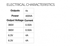
AS-4T360 - 400VA 360V Transformer - AnTek Products Corp
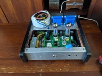
View attachment 900708
My thought is to connect the WHITE and YELLOW wires in the two 360v in to get 720V, and connect the YELLOW(0V) and WHITE(720V) to T1-RED and the same WHITE(0V) to T1-RED-YEL.
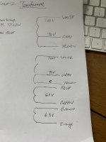
View attachment 900712
Is this the right way to think about this?
Thanks
Mark
We'd need a wire colour map for that tranny to say for sure, but maybe this will help:
The two 360V wires will go to T1-RED (with the middle binding block empty) and the center tap (0V) for the 360V winding will go to one of the T1-RED-YEL binding blocks. That's it for the 720.
360-0-360
By the way, I assume you are going to be running SS rectification, as there is no 5V winding for the rectifier tube heater.
So there are two yellow (0V) taps on separate windings?
WTF? That doesn't sound like a typical +360 0 -360 (center tapped 720) to me.
WTF? That doesn't sound like a typical +360 0 -360 (center tapped 720) to me.
It’s got two separate secondary windings. One white and one yellow connect together to make the 0v point and the other ends are the hv. Make sure you use use a white from one winding and the yellow from the other winding or you get a dead short! Also observe the polarity of the windings! Don’t wire them out of phase!
...
By the way, I assume you are going to be running SS rectification, as there is no 5V winding for the rectifier tube heater.
It is not hard to add a 5V winding to the Antek toroidal. I did and it powered the rectifier tube heater just fine. If interested it is documented in my build thread. Ultimately I decided to go with just the SS rectifier though so I removed it. Note my Antek is the smaller AS-2T350 transformer so the number of turns required to get 5V on the AS-4T360 would probably be different.
I did the same. I did ten turns of 18ga magnet wire and measured the ac voltage on it then figured the per wind voltage by dividing by ten. From there just divide five by the per winding voltage to get the number of turns you need. Easy. Spread the windings all around the core too.
Thanks, everyone for their help.
I was thinking of using two resistors (30/100) to drop the voltage since it is relatively low.
Is this a bad idea?
Voltage Divider Calculator
Going to go with Solid State rectification first....
I was thinking of using two resistors (30/100) to drop the voltage since it is relatively low.
Is this a bad idea?
Voltage Divider Calculator
Going to go with Solid State rectification first....
Is this a bad idea?
Yes, this is a very bad idea.
The 5 volt rectifier heater winding has to be isolated from the 6.3 volt heater winding as the full B+ voltage is riding on it through the rectifiers cathode.
Thanks, everyone for their help. I was thinking of using two resistors (30/100) to drop the voltage since it is relatively low. Is this a bad idea?
A voltage divider like you mention will NOT work. The current demands for the rectifier tube are too high for a voltage divider.
You can run a SSE board on a large Antek transformer like the AS-4T360 using one of two ways. I have done both.
As mentioned you can wind a new 5 volt winding to power the rectifier tube. I don't have a 4T360 so I can't tell you exactly how many turns to use. The wire should be 18 gauge or bigger (lower number) to handle the required current.
The AS-4T360 has two 4 amp 6.3 volt windings. Use ONE of them connected to the GRN terminals on the rear of the board to power the two output tubes and the 12AT7.
Connect a suitable resistor in series with the OTHER 6.3 volt winding to power the rectifier tube through the YEL terminals. Any connection between these two winding will make C3 explode. The resistor value will be different for each different rectifier tube. A 5AR4 draws 1.9 amps and a 0.72 or 0.75 ohm 5 watt resistor will work. A 5U4 draws 3 amps, so a 0.39 or 0.42 ohm 6 to 10 watt resistor will be needed.
- Home
- More Vendors...
- Tubelab
- Antek Power Transformer wiring for the SSE


