Amplifiers - Feedback/Loopgain stability simulated vs. real world
In many threads here I have expressed my doubts on accuracy of amplifier circuit simulations, especially in two points – very low harmonic distortions <0.001% and feedback (loopgain) unconditional stability. Based on my long, decades lasting experience in designing, building and testing power amplifiers I am declaring that transistor models available with freely distributed simulators like LTspice and others are not accurate enough to simulate neither very low levels of harmonic distortions, nor stability issues with complex load at frequencies >1MHz. I am going to prove my statements on the examples of two real world amplifier samples. And this will be also related to methods of frequency compensation of feedback amplifiers, based on Bode plots loopgain simulations.
Two amplifier samples will be analyzed, one with an old-school dominant-pole compensation, the other with more sophisticated TPC compensation, that allows for more loopgain at higher frequencies, thus lower harmonic distortion at higher frequencies. The amplifiers will be analyzed not only for distortion, but also for stability with complex load and this stability will be compared to assumptions derived from loopgain simulations.
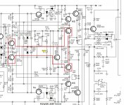
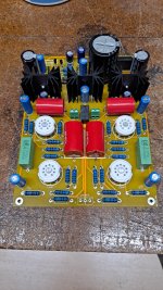
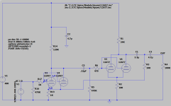
1. The amplifier with the dominant-pole compensation
The amplifier sample has been described here in the thread
https://www.diyaudio.com/community/...er-and-my-diy-mods-schematics-gerbers.406947/
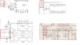
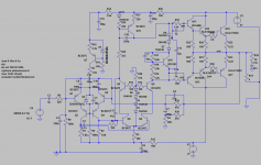
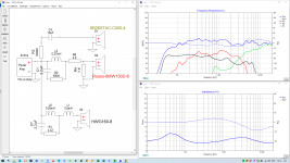
Loopgain simulation says that with a resistor load (4.7ohm) the phase margin at the point where the loopgain amplitude plot crosses 0dB, at 3.75MHz, is about 80°, which is enough for stable operation. The feedback factor (loopgain) at 20kHz is 41dB, which is the factor available for harmonic distortion reduction of this feedback amplifier, at 20kHz. At =<1kHz, the loopgain is 58dB.

Now, when 47nF capacitor is added in parallel with 4R7 resistor, the loopgain amplitude plot crosses 0dB at 2.45MHz and the phase margin is now a mere 14°, so the amplifier should be close to instability.
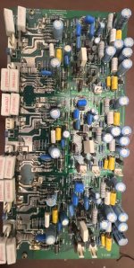
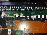
Let's investigate the real amplifier sample, with a 10kHz square wave as an input signal, and both discussed loads.
Response into 4.7ohm resistor

The response is nicely aperiodic, with no signs of instability. Exactly according to loopgain simulation.
Response into 4.7ohm//47nF

47nF capacitor was added in parallel with the 4R7 resistor, however the square response remained unaffected. This is not in conformance with the simulated loopgain, which would suggest at least heavy ringing, with the simulated phase margin of only 14°.
The amplifier is stable (in the real world) for wide range of capacitances, covering at least 0 – 100nF. First signs of compromised stability we can see with the 150nF capacitor // 4R7:

So, for this amplifier sample with dominant-pole compensation, the simulation was pesismistic compared to the real world results. Something does not fit, models?
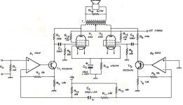
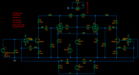
2. The amplifier with TPC compensation
The amplifier sample has been described in the thread
https://www.diyaudio.com/community/threads/sab-class-ab-2x50w-4ohm-amplifier-with-smps.386169/
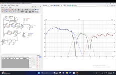
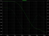
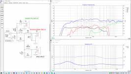
Loopgain simulation says that with a resistor load (4.7ohm) the phase margin at the point where the loopgain amplitude plot crosses 0dB, at 0.95MHz, is about 50°, which might be enough for stable operation. The feedback factor (loopgain) at 20kHz is 57dB, which is the factor available for harmonic distortion reduction of this feedback amplifier, at 20kHz. At =<1kHz, the loopgain is very high 93dB. Brown line in the graph would be a comparison to a dominant-pole compensation with the same unity gain frequency.

Now, when 47nF capacitor is added in parallel with 4R7 resistor, the loopgain amplitude plot crosses 0dB at almost same point near 0.95MHz and the phase margin is now a mere 30°, not much less than without the capacitor, and the amplifier should be still stable.
Another plot is with 15nF capacitor, and we can see that the phase margin is now 43°, definitely enough for the amplifier to be stable, at least in the simulation!

But how about the real world sample?? Alas, the amplifier's response oscillates with 4R7//15nF!

And increasing the capacitor to 47nF makes oscillations with much higher amplitude and the amplifier has suddenly blown the T5A fuse in the +rail of the power supply. But, due to very robust MJL21194/93 output pair, it has survived.
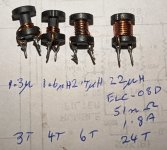
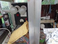
I inserted the 0.4uH output coil behind the amplifier's output ad now it was able to drive 4R7//33nF load with slight signs of oscillations only.

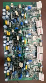
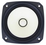
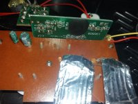
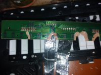
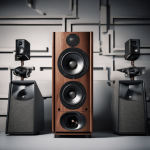
Test bench, load and output coil

So, with the more sophisticated compensation scheme, we have got this improvement in THD+N vs. frequency at the expense of much worse amplifier stability, though the simulations did not suggest the stability worsening.


It is up to you to make a choice, if you prefer some inaudible improvement in THD+N, or an unconditional amplifier stability. And remember, do not forget to use the output coil with feedback amplifiers!