Midrange substitution.

Hi everyone,
I have to replace the midrange of my speakers with a more performing one, with which I am not satisfied but I would like to improve.

Below you will find the dimensions of the current one, the external diameter is 123mm and obviously it can also be 120mm.
The internal diameter 98.2mm could be even more, i have no problem widening it, but it would be better not.

SB12MNRX25-4-drawing.jpg


I would prefer that the medium did not have the foam suspension like the scan speak illuminator midranges for example (it's a shame).
Both 4 and 8 ohms are fine

Please recommend me some mediums i could try any brand, or ask me questions if I omitted something, thank you very much!

Looking for transformer recommendations, Aikido octal

Hello all, can any on this site recommend a power transformer for my new build? I want to use the Aikido octal board and the PS tube kit with the 5y3 rectifier tube. the 270cax from Hammond is recommended on the glassware audio site, but I don't know if it's a good match for the octal board....I have also heard of set ups with 2 transformers. 1 for the heaters and separte for the B+

Puttin' oil into the audio fire: Swans DM-7500

HSB has scrutinized this little 3" bird from China (DM 7500) with very good results :

https://hifi-selbstbau.de

Full extended report only for members ($25/yearly subscription) , incl. passive filter network making bandpass FR flat to +/-1dB along the filter function ...

Don't ask me for giving away copies of the results of HSB test report , I'm just here because I don't like the extreme prices of ATC and VOLT ... and you'll see there are cheaper alternatives!

Btw - in the report they mentioned the idea to mount the dome driver from behind the baffle , and shaping the contour similar to the front plate profile of the DM7600 , nice idea! (fabric dome is very exposed due to large height)

A man without a hobby is braindead 🙂

https://de.aliexpress.com/item/1005004670052234.html

https://de.aliexpress.com/item/1005006747187144.html?src=google

Wiring of TRS microphone

Hi, in order to add an external input microphone line to my camera, I will add a 3.5mm TRS connector (such as this one) to switch between internal and external microphone. I intend to plug a basic condenser microphone, the Rode Videomicro that should fits my needs (link). The procedure is quite straightforward, open the camera body, cut the wire and that's all (here's an example link). It seems to work since people are doing it, but I still have some questions, I'm curious by nature.

From what I saw on internet, the TRS wiring should be the following :
  • Tip : input (mic -)
  • Ring : +5V bias (mic +)
  • Sleeve : ground
Source : hobby-hour and speechrecsolutions . I was expecting to find more "reliable" sources than random internet webpages so I'd like to have your opinion on this.

Also, do you think that the external microphone should be grounded with the rest of the camera board ? People seems to only link the two cables used by the internal microphone and finding a spot to solder an external ground cable on the camera board may be challenging.

This may be a bit off topic for this forum but I didn't see where I could ask recommandations...

Beyma TPL-75 + Purifi PTT5.25: Peggy Lee, "Fever" (1958)

<iframe width="560" height="315" src=" Login to view embedded media " title="YouTube video player" frameborder="0" allow="accelerometer; autoplay; clipboard-write; encrypted-media; gyroscope; picture-in-picture; web-share" referrerpolicy="strict-origin-when-cross-origin" allowfullscreen></iframe>

My ongoing development project, this time featuring Peggy Lee's "Fever." I had not known until recently that Miss Lee wrote additional verses for this song, including the Shakespeare quotations and allusions. I owe debts of gratitude to Corwin Butterworth, Jim Tuomy, and Curt Campbell for their wonderful contributions to this 2-way loudspeaker with Passive Radiators. The crossover point is 2.4kHz; the box tuning is circa 42Hz, and there is extension to circa 34Hz. Largely because the Fs of the PTT5.25 is 32Hz, while the Passive Radiators (two per speaker) have an Fs of 20Hz.

The client approves, so, it's time to build the other speaker of the pair!

john

Problems with Chinese PP kit

Hi all,

I’m new to the group and was wondering if anyone here could shed some light on a problem I’m having with this Chinese amp kit I am working on. I do have basic electronic knowledge and was building amps (solid state) and speakers many, many moons ago…. Now, returning to this hobby almost 30 years later, I am a bit rusty. Also, forgive the long-winded post.

No model number really, it goes by: “HiFi Class AB Tube Power Amplifier DIY Kit Push-pull Stereo Audio Amp 12W+12W”. from Doukstore.
Using 6F2 pentode-triode for pre and phase reverse, and two 6P1 (beam tetrode, as far as I know).

The kit came with no instructions whatsoever (they do say that), other than some pictures and the schematic drawing (attached). I assembled all the components on the PCB, PSU and all the in/out plugs.

Plugged it in for testing: isolation variac and current limiting (light bulb). Hooked up 8-Ohm dummies and started bringing it up slowly on the variac. Somewhere around 90V, I started hearing oscillation sweep coming from, I think, one (or more?) of the tubes… not sure which one(s). oscillations started at the low audible range around 250Hz, going up to 1-2K and staying there. Ran the same test with real speakers (which I very quickly regretted), and the same oscillation happened again, only mush lauder now. It kept doing the same thing at 110-117V.

Since then I have:
swapped tubes (as in the left ch set with right ch) - same results
replace all tubes with new ones – same results

Decided to rebuild the thing, not using the PCB, as I thought it was poorly made and may have become microphonic or conductive or something, so I rebuild it point-to-point (I can read and follow schematics pretty well) using multiple star-ground points, and replacing many of the caps and resistors with better quality parts (at least that’s what I believe I did) – same results

third build – P2P & repositioning components & different grounding scheme: bus bar hitting chassis in one place only – again, same oscillations…

didn’t replace the irons, the rectifier and reservoir caps.

Not sure what the deal is, I doubt it could be poor design, as they are selling those things, and I don’t see any bad reviews about this product.

Another thing – as I said, I do have basic understanding of how this works, but I’m no expert, nor a designer, just “following the plan”. However, I have compared this schematic with a few other PP designs, and although they are all different, some elements do repeat themselves. I’m not sure I understand the two res and cap network that feeds into pin#9 of the 6F2 (36K; 82K; 100pF). I haven’t seen this anywhere else (yes, I realize there must be hundreds of designs out there, and no, I didn’t look at them all 😎), but – does this look genuine? I feel something is missing there, like a grid resistor, or a decoupling cap, or am I completely off?
Any input would be highly appreciated!
/DL

Attachments

  • 20200211104349.jpg
    20200211104349.jpg
    109.6 KB · Views: 2,176

No gain without pain ? low gain circuits vs buffers

Hi ! after i discovered LTspice and kindly got very good settings i started playing with very basic circuits
I have a CFP circuit It can be wired either as low gain line preamp or as unity gain buffer just taking out the feedback resistor
My impression after trying different resistors and voltage supply values that gain usually introduces about 10 to 20dB of 2nd order HD ...
I mean for the same 2V output the 1kHz distortion spectrum of the buffer looks much cleaner
Does this mean that generally adding gain tends to increase THD ? even if the gain is just 2 o 3 times ?

Building an Audiophile DAC

Hello All,

I’m embarking on building my first DAC.
Here are some details:
1) I want to take input primarily from a CD transport. I also want to be able to play .wav files (via a MacMini).
2) Having built a tube phono amp, and a tube preamp, I’m handy with tools and a soldering iron.
3) I’d like this DAC to be fairly high-end as I’d like it to provide the spaciousness, depth, smoothness and definition of vinyl.
4) I’ve been looking at the Gabster YouTube videos and I think that his Flagship DAC is the one that I’d like to build, although the TDA1541A DAC looks good too.

Any suggestions, thoughts and recommendations would be greatly appreciated.

Also, does anyone have Gabster’s email address?

Thanks,
MoodyhhDAC

For Sale Quasimodo test-jig V4 PCB

ALL pcbs are gone / sold!

===================================================


Hello,

here I offer Quasiomodo v4 pcbs from Marc Johnson.
(Simple, no-math transformer snubber using Quasimodo test-jig)

costs x€ each pcb

Shipping in padded envelope (not insured, not tracking) to
  • Germany (without islands): 2,50€
  • Shipping in EU: 4,50€
  • UK: 10€ as small parcel (because Brexit & new custom laws, not insured, not tracking)
  • other countries please ask

preview

3 way 12/db LR question

I am re-working a xover I built some time back that is for a 3-way design.

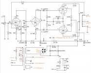
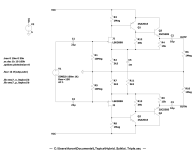
My design is essentially this:

https://sound-au.com/project81.htm

While my design is a 3-way, it is literally just a single adaptation of the above. All I have done is taken the signal that comes off the high-pass filter block and fed it back into another 2-way network.

-> The low pass from the initial network goes directly to the low frequency amplifier.
-> The high pass from the initial netowork goes into the SECOND 2-way network
-> The midrange is fed through the SECOND low pass out
-> The tweeter is fed through the SECOND high pass out

All this is done w/ active circuitry - this is NOT a passive crossover.

So now I am wondering how the phase shift is going to play out...

The two outputs from the initial filter are each 90 degrees out-of-phase from the input - so 180 total.

The outputs from the second filter are also each 90 degrees out-of-phase from the output of the first filter. So correct me if I am wrong but...

1) Tweeter and midrange will be 180 out of phase from each-other
2) Midrange and woofer will be 90 out of phase from each other, no?

In the second filter, the midrange is delayed another 90 degrees - bringing it back down to where the original signal should be - and since the woofer was delayed 90 degrees from the original signal to start, we have a total of 90 degrees difference between woofer and mid - correct?

So there is the first question - am I understanding the phase shift correctly?

Question 2: Is this 90 degree going to be much of an issue? I suppose that the driver VC offsets can affect things much more than this 90 degree offset imposed at the xover.

Question 3: I suppose I could use any arbitrary 1st-order filters back-to-back to provide the 90-degree phase shift needed to bring the woofer back into relative phase with the tween and woofer network, no? Any RC or CR network set that is well above the woofer xover frequency would basically each provide 45 degrees - giving me 90 total.

Now for the one I have been wanting to ask for YEARS....

Question 4: I am not a math junkie and never got anything beyond my high school education in math. So forgive this ignorance but..

I understand how you can delay a signal by 45/90/etc degrees. That makes perfect sense. Energy gets stored in the network and released a tiny fraction of time later - delaying the signal that is output.

But how on earth does the high-pass signal get "moved forward"?!?!?! Forgive me here - but even with advances in quantum mechanics, we have not fully developed time travel in actual practice, so... How can a signal be shifted 90 degrees FORWARD? I am - ovbiously - thinking about this in the time domain. So to shift a signal FORWARD, you have to move the entire time scale BACKWARDS. What am I missing here?

Soft Dome Tweeter Coatings

Hi all,

Ive become fascinated in the technology that is involved in coating tweeters to help reduce their resonance and/or even their frequency response.

My question is:

I would like to experiment with tweeter doping (i know i know, not too liked around here), in doing so, what are the most recommended doping/soft dome coatings recommended out their? (not too crazy about water soluable materials, i want it to last- ie no mod podge). Eventually i would like to construct my own soft-dome tweeters but i cant seem to find out this type of information anywhere.

In particular, i prefer the Dynaudio soft domes. To me, they have the perfect balance of acoustical characteristics.

So, does anyone know any good doping/coating materials used for the construction of lightweight soft dome tweeters similar to the Dynaudio ESOTAR's?

Unable to understand the OP-Amp Section

Hello to all. My knowledge of circuits and power amplifiers is quite limited from an academic standpoint. The PCB board schematic that arrived from China is something I'm attempting to sketch. Furthermore, I am unable to understand the OP-Amp Section.

It makes sense if JP1's pins 2 and 3 and JP2's pins 1 and 2 are connected, but what about JP3? Single Jumper in the left channel. What does R83 accomplish?
JP1 and JP 3 will be a potentiometer?

Would you mind giving me some opinion on this, please? that your advice would be helpful to me with this endeavor.

Thanks
opu

Attachments

  • DSC_0238.JPG
    DSC_0238.JPG
    326.9 KB · Views: 170
  • amp_01 copy.png
    amp_01 copy.png
    230.5 KB · Views: 184
  • DSC_0239 copy.jpg
    DSC_0239 copy.jpg
    507.9 KB · Views: 171

Krell KSA80B - no bias pot?!

I checked into my KSA80B amp for some minor repair on the protection board.
Needed to exchange the ROE 470uF in the power supply. While case was open I adjusted offset on one channel and was able to adjust from 50mV to around 6mV.

My emitter resistor voltage was measured to 200-220mV (4 places). This is a bit low as manual states 325mV for correct bias.
Now to my concern, I’m not able to find a trim pot for this! Even with glasses on and flashlight I couldn’t find a second pot on the main board.

Does anyone have a correct lay-out to share or can advise?
Thanks

What is this component?

Hi

Long time lurker first time poster!

I have a spinning speaker from a Yamaha organ which I am trying to get working. The speaker works fine it’s the motor that doesn’t spin. It turns but at about 5rpm, should be running at over 1000rpm I suspect.


I have found a burnt out component but don’t recognise what it is and searching google doesn’t bring anything up. Best I can guess is that it’s some sort of diode? It says IR2C with a blue band around it. There’s five of them and one has gone black. It’s the obvious fault at this point before I go changing anything else.

Does anyone know what this part is please so I can set about replacement? The first photo shows the part I’m on about and the second photo shows the particular part burnt out.

I would really like to get it working so would very much appreciate any input.

If it helps it’s from the early 1970s I believe.

Cheers!

Attachments

  • 9F9BB96D-F13C-48C7-B8F9-8620A76DCEDE.jpeg
    9F9BB96D-F13C-48C7-B8F9-8620A76DCEDE.jpeg
    446.6 KB · Views: 110
  • FCA5C479-91CF-41FC-B0E8-09D796BDA6F8.jpeg
    FCA5C479-91CF-41FC-B0E8-09D796BDA6F8.jpeg
    388.3 KB · Views: 111

toroidal transformer wiring question

Hope someone can help me id this power transformer and specifically how to wire it for 120V. It has 6 leads on the 2 primary cores, and my very limited knowledge tells me that this is to simplify wiring it for 240V power source.
But I need it wired for 120V for my DAC
Also, when testing with a multimeter I get about 3.7 ohms between red and white leads, but nothing between black and red or white. Does it mean something is wrong with it?

Thanks!
CT-5082 label.jpg

connecting two runs of speaker wire

I have question about connecting two runs of speaker wires together. I have an Aragon 8008bb bi-wired to B&W N803s with an 8-foot run of 12awg XLO cable. I plan to sell the Aragon and power the speakers with an amp in a different room. I would like to keep the XLO bi-wires connected to the speakers and connect their other bare ends to a 15-foot run of wires coming from the other room. I could solder them together and cover with shrink wrap or connect them using copper binding lugs. Would that work OK? What would be the best connection?

Going Active - Discrete parts or Hypex Fusions?

Going Active - Discrete parts or Hypex Fusions?

Hey Folks!

I am considering how to go active.
I’m a little torn between the Hypex FA253 served by a Wiim Pro Plus (digital output) or a discrete stack that looks roughly like Wiim Pro Plus (digital output) -> MiniDSP Flex HT -> Amps (Example: Fosi v3 Monoblocks).

Use case:
DIY Active speakers - 2 or 3 ways.
Fully digital sources (I own 0 physical media and will not need any ADC)
Will likely want to integrate subwoofers.
If Flex HT - could be used for 2 way LCR or room correction for 5.1/7.1 at some point if it gets retired from Stereo.


Hypex

Pros:
Simple
Clean
One system - easier support, all built to work together.
Minimal gain management
No testing new parts

Cons:
No testing new parts
Subwoofer out is harder?
Only 3 channels per speaker.

Active Stack

Pros:
Can test new parts.
Can manage subwoofers with extra channels of DSP
Can swap Flex HT into home theatre use if it gets replaced later
Can accept HDMI input from a TV.
More power available (depending on amp choice).
Global volume is easier.
Can get DIRAC

Cons:
Need to deal with gain management.
No Balanced output from Minidsp Flex HT.
Slightly more expensive.


Pricing:

Hypex
$290 AUD - Wiim pro plus
$1993 AUD - 2x Hypex FA253

Stack:
$290 AUD - Wiim pro plus
$951 AUD - MiniDSP Flex HT
$1125 - 6x Fosi V3 Monoblocks (example amp - kickstarter prices).

Hypex: $2283
Stack: $2366

Are there any points I’m missing?
Am I missing hardware options of a comparable quality and price?
What would you do?
Am I overthinking this?
Are there better diy amp solutions?

Restrictions:

Please remember in your discussion: I am using purely digital media - No ADC is considered or needed. I will NOT be collecting vinyl or CD’s at any stage.

No CamillaDSP etc. I need the dsp to be standalone.

No big price increases. $2 - $2.5k AUD is about all I want to spend.

Love to hear your thoughts!

Cheers

Inductive interaction/coupling between inductors test

Inductive interaction/coupling between inductors is many times underrated/ignored and some times just tested on how the inductance changes between coils which is just one part of the real problem.

I was researching about crossover inductors position practices myths and facts(see here) on how audible and at what power levels this really became a problem but I was unable to find any A/B blind tests on the net.

Then to make the long story short(sorta), I was completely chocked on my own findings, I was able to drive a compression driver connected to an 0.7mH 20AWG inductor by exiting an 1.5mH 14AWG inductor and placing them just few inches in the lay-down position, the closer they become the louder the compression driver becomes, and in the recommended position I fount that putting the outer windings out of phase is the least affected position.

My tests was very simple and no expensive measurement gear was required.

Used parts list if some what to reproduce the tests(parts don't have to be exact):
1) An 1.5mH 14AWG inductor.
2) An 0.7mH 20AWG inductor.
3) An 33uF MKP capacitor.
4) An non-inductive 20W resistor.

I've used a piezo compression driver for the test as those things are sensitive but I believe any sensitive 8-ohms CD can be used as well, also I've used a standard Class A/B amplifier and put some load(fast electronic music) into an 12W 5-ohms resistor until the 1.5mH inductor made some electro-magnetic field to make an screw driver vibrate inside the hole then I've stopped increasing the volume, at this point the 12W 5-ohms resistor is hot to the touch but not burning, to my surprise I was able to even hear the kick-drum into the compression driver😱.

To conclude this simple test I believe that even 4 inches of proximity is not enough for lay-down oriented crossover coils, also the most affected are the users of high sensitivity speakers such as compression drivers.

Here is the simple test diagram:
Inductive interaction-coupling test.jpg

Here is the recommended inductor position with coil outer windings out of phase:
IMG_4182_Small.jpg

Here is the modified crossovers from my old bookshelf speaker build, the midrange is way cleaner at high volume and the center image is now wider and immersive:
IMG_4185_Small.jpgIMG_4187_Small.jpgIMG_4188_Small.jpgIMG_4195_Small.jpgIMG_4196_Small.jpg

Regards!
  • Like
Reactions: rayma

2 way crossover design - Assessment needed

Hey everybody, I just finished putting together a 2 way crossover design in Xsim. I have generated my own .frd files with the drivers installed in the cabin, and traced the .zma files from the manufacturer's specs.

Overall I am satisfied with the outcome. But before I give it a go, I'd like to hear your remarks for I am an absolute beginner. I am especially curious about how you would interpret the impedance graph, given the peaks are rather high up on the scale. Should I be worried or is this fine?

WhatsApp Image 2024-05-23 at 23.36.54.jpeg
.
WhatsApp Image 2024-05-23 at 23.36.50.jpeg


For reference, I am attaching the manufacturer's graphs for both drivers:

sb15nrxc30 (8 ohm)
Screenshot 2024-05-23 at 23.47.46.png


Morel MDT29 (8 ohm)
.
Screenshot 2024-05-23 at 23.47.13.png


Thank you!

Anthology II in MDF or Plywood?

Warning: Noob questions incoming. I'm planning on investing quite a bit of time and effort into the construction of a beautiful cabinet, so I need some help deciding on the material. When it comes to MDF, I'm a bit concerned about it absorbing moisture from the air over time or that the construction might not be as strong as plywood and could get wobbly over the years. Plywood should be a superior choice in that regard, but I'm unsure how its lesser density and uniformity affect performance.

If I go with MDF, would applying a sealant on the inside and veneers and finish on the outside seal it hermetically, making it last longer? I'm planning on keeping the speakers for a really long time, so longevity and build quality are important factors to me. Perhaps I'll even fit Anthology III inside the enclosure in the distant future 🙃.

Also, how difficult is it to maintain the speaker and replace the dampening on the inside, since it's probably the first thing that will rot out over the years? Another question I have is regarding the slightly rounded edges that are on most of the Anthology builds. How would the speaker fare without the roundover? I've read that the roundover is too small to have a significant effect on refraction, but I figured it would be best to ask you guys.

Thank you for reading!

Servicing a Technics SL-Q5 Linear Tracking Turntable

I found that there are a few of these for sale on eBay lately. Now 40 years old the grease has thickened into a sticky glue that impedes the motion of the tone arm on the rail and the little belt gets stretched so it often doesn't work. Fortunately the belt is readily available and the grease is pretty easy to clean off following videos on youTube for similar models. I could not find instructions for how to align the tone arm or clock frequencies on the web, so I bought the service manual. As it has no copyright notices anywhere to be found on it, I scanned it and have attached it here. Technics SL-Q5 Service Manual.

Attachments

  • Like
Reactions: mikey_audiogeek

Help with Aikido Line Stage Decision

Hi,

I would like to ask for advice on what of the 3 Aikidos that glassware offers (octal, noval and 12v) is easier to put together. I am a long time audiophile and I know how to solder and I am learning how to read a schematic, but I have some doubts as to what is the best Aikido line stage from those 3 you offer for my specific needs.

For my needs, I just need one single line level input, because I mostly listen to music from my DAC.

Regarding those 3 Aikido's, are there any evident differences in sound between the ones that require a power supply (Octal and Noval) in comparison with the 12v one?

How hard is it to put together the Noval or Octal kit with the PS-21 that glassware also offers?

Thanks,

Alan

Tung Sol 6SN7

Clearing out odds and ends.
Bought this NOS from vacuumtubes.net a few years ago. I have no use for it now. Works great. I always ran my RCA in place of other 6SN7 brands so this has virtually no usage whatsoever.

$30 + $6 shipping.

I also have a pair of Sylvania 5U4G that I'd throw in for free if desired.

Attachments

  • PXL_20240602_042905084.jpg
    PXL_20240602_042905084.jpg
    277.2 KB · Views: 65
  • PXL_20240602_042847578.jpg
    PXL_20240602_042847578.jpg
    208.7 KB · Views: 65
  • PXL_20240602_042736212.MP.jpg
    PXL_20240602_042736212.MP.jpg
    234.7 KB · Views: 68
  • PXL_20240602_042721540.jpg
    PXL_20240602_042721540.jpg
    393.9 KB · Views: 69

Kaisaya HiFi Audio - Schematics wanted for Accuphase clone and Music Fax' Power Amp

Accuphase model "E405"-clone and Music Fax Power Amp "F18" and "A-1000" from Kaisaya HiFi Audio - Schematic wanted

For the follow products I am looking for schematic diagrams:

2pcs E405 Gold Seal Tube Post Grade Amplifier Board Class A High Power HIFI AMP Circuit Module 200W MJ15024G/MJ15025G/2SA19-in Amplifier from Consumer Electronics on Aliexpress.com | Alibaba Group

E405 power amplifier board (reference circuit Accuphase) (1 pair) in E405 power amplifier board (reference circuit Accuphase) (1 pair) aus Schalterkappen auf AliExpress.com | Alibaba Group

MJ21195 MJ21196 MJE15032 MJE15033 BC546B BC556B WIMA MKP10 2.0 250W Music Fax F18 Class A Postposition Power Amplifier Board in MJ21195 MJ21196 MJE15032 MJE15033 BC546B BC556B WIMA MKP10 2.0 250W Music Fax F18 Class A Postposition Power Amplifier Board aus Verstarker auf AliExpress.com | Alibaba Group

MJ21195 MJ21196 MJE15032 MJE15033 BC546B BC556B WIMA MKP10 Musik Fax A1000 2,0 60 watt Klasse A Endstufe in MJ21195 MJ21196 MJE15032 MJE15033 BC546B BC556B WIMA MKP10 Musik Fax A1000 2,0 60 watt Klasse A Endstufe aus Verstarker auf AliExpress.com | Alibaba Group
MJ21195 MJ21196 MJE15032 MJE15033 BC546B BC556B WIMA MKP10 Music Fax A1000 2.0 60W Class A Power Amplifier in MJ21195 MJ21196 MJE15032 MJE15033 BC546B BC556B WIMA MKP10 Music Fax A1000 2.0 60W Class A Power Amplifier aus Verstarker auf AliExpress.com | Alibaba Group

Thank you very much for upload.

The brand "Music Fax" I have never heard before, but the board of power amp so as the completly device looks both very impressive and well made.

2SK389 2SJ109 matching

I've come into a few hundred 2SK389s as well as few hundred 2SJ109s. I want to try to match them up and then sell the pairs on Ebay.

I've done JFET matching before but not with IDSS method. What I have done, for sensor applications, is measure the VGS for both sides of the FET at the bias point, or very close to it, of the final circuit.

What is typical bias point for audio applications? I was thinking 9V and 5ma, but I really have no idea.
  • Like
Reactions: mrjayviper

For Sale Aluminium Case For Class AB Amplifier With SoftStart And LED Push Button

Here i have Aluminium Case that is used for Class AB Amplifier. I buy that aluminium case and drill a few holes inside heatsink to mount audio amplifier. But i sell that amplifier to member here in diyAudio forum so i got the case that is like new, without scratches or any phisically damage. It comes in protection box that is ready to ship for happy buyer here, and comes with softstart inside box and dual bridge rectifier, volume aluminium knob and push button for on/off that have LED inside.

Heatsink size is 42cm x 13cm x 32cm and are two heatsink, each at one side of aluminium case. From aluminium plate is 8mm thickness and it comes with screws and all accessories that came with the box.

These heatsinks can cool 200W/8R Class AB or 40W in class A, so it is intended to use as audio amplifier case with nice looking style and LED push button for on/off.

At rear it comes with golden speaker terminals, and integrated fuse inside AC conector from rear side so user can change fuse if it is needed.

All in all, very nice aluminium case with nice look and performance for Class A or Class AB project.

Price is €232,00 including free shipping to EU country and paying with paypal. PM with your shipping address and i will replay with my paypal data. Shipping will be with tracking number to buyer address.

Attachments

  • 1.jpg
    1.jpg
    79.2 KB · Views: 163
  • 2.jpg
    2.jpg
    75.3 KB · Views: 138
  • 3.jpg
    3.jpg
    79.4 KB · Views: 139
  • 4.jpg
    4.jpg
    73.4 KB · Views: 157
  • 5.jpg
    5.jpg
    73.1 KB · Views: 155
  • 6.jpg
    6.jpg
    43.7 KB · Views: 152
  • 7.jpg
    7.jpg
    49.4 KB · Views: 147
  • 8.jpg
    8.jpg
    40.6 KB · Views: 176
  • 9.jpg
    9.jpg
    66.3 KB · Views: 155
  • 10.jpg
    10.jpg
    80.6 KB · Views: 178

Armboard experiments and calculations

All,

I'm currently into constructing a new armboard for my all DIY turntable and Schröder Clone tonearm.
Here's the history.

I started out with an armboard entirely made of aluminium.
IMG_5626.jpg


Sound was quite good - until I tried making an armboard from Panzerholz (same material as the plinth is build from):
Unbenannt1.JPG

The first version was without the copper disks. The soundstage was already way better than with the aluminium armboard - but it was lacking bass.
The two disks glued together with a viscoelastic glue cured that.

And now I beleive that there is / may be some potential left that I can unearth with a proper approach.

What I did was calculate the resonance freqauencyof the tonearm based on the effective mass of the tonearm: 8,05Hz.
As I read in one of the few threads that seem to be reasonable if it comes toi matchng armboards to tonearms, the mechanical impedances of both should be a match.
So I've calculated the mechanical impedace (with a little help from chatgpt) Zm = i1,752Ns/m based on the resonance frequency of the tonearm.

And this is where I'm lost and stuck. If I now would like to make the armboard of Panzerholz or a composite of different materials - say Aliminium/Panzerholöz/Aluminium - how would I calculte it's dimensions?
Or am I entirely wrong with my approach?

Best Stephan
  • Like
Reactions: rayma

Meridian 206 CD woes

Bought it broken to compliment vintage Meridian pieces. It was exhibiting typical TDA1541 crackling sound symptoms and as a transport it only played first few tracks and refused to go forward. I thought it will be rather easy fix but I was wrong. I replaced TDA with a chip from donor board I vaguely remembered it was working. Voltages seemed correct but it didn't help. There was no output at all. Frustrated I pulled the chip and put it in my DAc .It was working fine . I checked old chip ( S1) and surely enough it was fried. I put it back , checked and re re checked and again nothing. I cut out Meridian output IV stages and installed resistors to check nothing at all. Damn it. Since no schematic is available decided to use machine as a transport only and pulled the chip again which pretty much damaged fragile plated throug PCB tracks. Still salvageable and I have 28dil socket on order. Back to transport. Thinking that recap will fix the tracking issue I took it apart and replace servo capacitors, Psu caps and all el caps around transport serving chips . Nope . The mech is rare as hen teeth CDM4/21 . It's not an issue with clamp since Meridian is using custom clamping arm where nothing wears out. It's just a plastic platter spinning against flat metal surface. Player plays 3 to 6 first tracks then servo makes some screechy sounds and the playback stops. I didn't get to mechanism own control board with potentiometer not seeing any capacitors there.
Anybody familiar with quirks of this machine. I replaced SA7220ap and it made no difference. Bummer

Why i am not getting chest kick? from a 1000w subwoofer (car audio)

I know that midbass is the hardest thing to fix in car audio , but even outside or in house my subs didnt hit, they where just loud af.
i had only 12" subs. Rockford t2 and alpine type x. The t2 was so nice in a small box
Why a 1k sub can't hit you in the chest and a crappy 15" 100w pa driver can?

is Sd my problem? Or is the vas and cms, mms. bl

Now i have an eclipse sw8122, 12" 140gr mms, high cms with 90L vas! 21bl, 500w rms on paper but can do a little more.
Is the same, so is not that. This eclipse is a very efficient sub, qts is 0.3 so the box recommendation is small. Is a nice sq sub

Or is just my taste in old school subs?


(I am buying old subs (only in good shape) because they are cheap, and i can sell them for the same price or more. New subs can be expensive, i am from europe, we dont have cheap good subs brands like in usa)

OB baffle design options

So...I have my drivers, I've tried a few prototypes, and I feel like it's time to get serious and I need to choose an overall geometry. I'm new to this and could use some help narrowing down baffle approach. I would say complexity and materials are irrelevant as I have access to CNC and design experts.

One main thing I don't fully understand is mounting the drivers. Rear mounting with chamfer or round over vs front flush mounting. I guess if someone wanted to give me some Coles notes on that I would appreciate it 🙂


I'm doing 18" (SB audience bianco18sw450), up to about 80hz, then 12" (jbl123a) up to... probably 500, then wide range (sonido 096 field coil)to 8000, then a tweeter/super tweeter, probably rear firing. Or I may let the wide ranger go all the way with no tweeter, not totally sure yet.

It is active and will be using minidsp for the two woofers so I can eq as needed.

Here are some primary options as I see it...

1. Wide baffle all the way, around 20" wide and around 45" high, with gradual round over on the edges, similar to the Sonus Faber Stradivarius U frame or partial uframe for the 18".

Reasoning: the wide baffle with large round over seems to give good defraction characteristics for the higher frequency. Pretty good looking if a little large.

2. Do the midrange completely baffle-less mounted somehow above a more traditional flat, wide baffle for the woofers.

Reasoning: no baffle at all for mid-high has best defraction characteristics...? The woofers will appreciate some baffle for cancellation purposes

3. No baffles anywhere. Nothing extends beyond the drivers.

Reasoning: again, defraction characteristics and off axis for mids and highs is good. Lows have zero baffle coloration. Also zero cancellation mitigation so needs a lot of eq.
Can look pretty cool.

4. Triangle. Baffle gets progressively larger as the drivers get larger. I could imagine benefits for off axis response similar to offsetting drivers due to the fact that the angles are changing for each driver, vs a parallel+perpendicular shape of a rectangle. Can look good.

5. Separate, different shapes baffles. Sort of looking at the pap construction but using the size most suitable (determined...with edge software?) for each driver. Similar to the triangle idea but with rectangles basically, and more flexible on size since each is separate. Large round over on all angles would perhaps guide much of the wave off the baffle before it hits the next baffle/driver?

Other factors, possibilities:
  • mount drivers in felt only, inlayed in a baffle
  • rear mount with drivers just barely touching baffle to reduce vibration

I may be wrong thinking in some, most, or all of this, because I'm new and dumb...

Help with increasing gain in headphone circuit

I bought some headphone amp boards from a local electronic store with quality parts and a really good design, but I could use some help figuring out how to increase the gain for some more output. I currently use two pairs of headphones that are 250 and 300 ohm and I find myself having to turn the volume up 3/4 of the way for normal listening levels where my Whammy I can't even get to halfway.

The headphone amp boards were supposed to come with four LME49710 but two were missing. I am instead using Burson Vivid opamps (V5 pair & V6 pair) now in all four positions. I am using a VRDN set at +-15 Volts.

I am wondering if I NEED to use LME 49710 in all 4 locations (or maybe just in the inverting circuit) to get the unit to perform correctly or if I can change a couple resistors to increase the gain without changing the distortion. The part of the circuit I believe I need to focus on is this one. Could I safely change R10 to 6.8k ohms to result in a gain of 10 where previously it was 5.9.

Or, should I adjust the gain in Stage 2 where it is set to only a gain of 1? I have included the full documentation of the headphone boards in the attachment.

Any help is appreciated here. I really like this circuit but could appreciate it more if it had some more UMPH!

1717085778335.png


1717086181277.png

Attachments

Simple high voltage regulator suggestions

Hi,
I would like to use a simple high voltage regulator for a SE project.

I came out with this preliminary schematic, where the feedback of the output ripple to the gate of the main mosfet (M1) is given by a mosfet (M3) loaded with CCS (M1) to maximize its gain so its correction (idea taken from @SpreadSpectrum Corona amp, where he loads a pentode by a CCS to maximize its gain and apply more nfb).

1716885168252.png


On simulations, supplying 100 mA with a 20Vpp ripple at infeed I get 600 uVpp ripple at its output, that is a 90dB reduction.
It seems too optimistic, so... what am I overlooking?

I know all safety measures for turn on/off are missing, but that will be checked and then asked later on.

Thanks in advance

Rebuilding and replacing old bridge rectifiers in vintage gear

This questions specifically involves the S5151 and S5151R which are dual diode devices with either common cathode or common anode and the pair are used in many vintage pieces of equipment to rectifier the AC coming from the secondary windings of the power transformer. In all the years I have been doing this I have read, been told that they are 5A diodes. In a pretty much identical case is the SS3 and SS5, the SS3 being rated for 3.5A and a smaller version of the package and the SS5 being rated 5A and the same size as the S5151. Unfortunately there are no data for the S5151. There are some threads I came across where members were asking about changing these out with discrete components and members like Echowars and Avionic which definitely know their stuff recommended 5 amp diodes as replacements like the HER504.

So I showed my replacment of these dual diode packages using MUR550 as I wanted ultrafast soft recovery diodes in place. They are 5A 570v rated. There is one full bridge for each channel of amplification on a Pioneer SX-1250
IMG_1259.jpeg


It was then brought up by another member, I won’t call him out (hopefully he’ll respond here, but he too knows his stuff as well), that the S5151 may not be 5A rated. He brought up the fact that the SX-1050 uses a 20A rated rectifier, so 10A per channel for less output power. So why a smaller rectifier for more power? I suggested that the rectifier may have been overkill, they could have put a 30A or 40A in there.

I then brought up the fact that the SX-950 which is 85 watts per channel, so 170 total (10 more watts total than each channel of the SX-1250) used a quad of the SR3AM diodes, both channel share the one bridge rectifier. The SR3AM is rated for 2A continuous or 3A with a heatsink which they didn’t use.

He then brings up a conversation that he was having with someone wanting to use 1N5404 (3A rated) in the SX-950, but he felt they weren’t adequate and recommended the need for 6A rated diodes. Why would an amp that came from the factory and has been working for nearly 50 years on 2A rated diodes (3A with heatsink) need 6A? The SX-950 runs at lower rail voltages than the SX-1050 and SX-1250.

So I figure if the SX-950 can make 170 watts output using 2A (3A with heatsink) diodes why can’t the SX-1250 make 160 watts using 5A diodes? I’m still convinced that these S5151 devices are 5A. I set up the bride rectifier so that I could measure the current in the SX-1250 and into clipping the amp heavily the highest I saw was a little over 900mA, but of course I wasn’t seeing peaks.

Regardless I put the SX-1250 back together with these new 5A MUR550s installed and it’s been playing for over 24 hours straight, blasting it pretty loudly during the daytime hours playing into my ADS L1590/2 and ESS AMT 1B. They may not be the most demanding load, but it’s been perfectly fine.

But for me it’s down to the fact the SX-950 makes slightly more power total on a lower current rated bridge rectifier and that for as long as I can remember the original has always been thought to have been a 5A device.

Thoughts?

Dan

Looking for some 2SK117, do I even need to buy any?

I have been looking to pick up some 2SK117s for some time, but knowing they are no longer produced, the likelihood of getting fakes are pretty high. I know that things can be faked to make the item look as authentic as possible, but I found this seller out of Japan, has 100% positive feedback, and if he indeed has the original box and such, I would put my money on these being authentic. Does anyone have the same opinion of them?
IMG_1313.jpeg


I’m wondering if I even need them though. I know this is all circuit dependent, so in the end I guess really wouldn’t know. I have at least a couple hundred each 2SK170 and 2SJ74, that I know with absolute certainty are the real thing. In most instances would the 2SK170 be a good sub for the 2SK117? In what instances would it not be a good sub other than circus that use higher than 40 V? Another option I was thinking of was using the SMD part 2SK209, putting it on a small adaptor board. It does have about half the dissipation of the 2SK117 though.

I like having large quantities on hand, especially if things are no longer available, which is why I have a couple hundred each of the 170/74 combo. So I don’t mind buying 200 of the SK117 and if I were to get the 2SK209 I would grab a couple hundred of them as well.

I was hoping to get opinions of others in here. If those 117s do look authentic would it be best if I grabbed those or do you think in 99% of instances the 170 will work? Or with the combo of the 170 and the 209 I should be good to go?

Dan

tunable gain preamp

hi everyone.
instead of using a fixed high gain electronic module (whatever the technology) and an attenuation pot (whatever the technology) , why not have a preamp circuit that exhibits from the start the exact gain needed according to the source output level, amp sensitivity and listening level chosen ?
For instance, with today's sources and amps and at usual listening level, you often need a say 0dB gain preamp so your common and possibly very expensive 20dB line preamp has -20db of attenuation in front or in tail. Not the shortest road ... As we say in French : "Quand le tabouret est trop bas, on coupe les pieds du piano". By the way, most line preamp designs have in reality an enormous gain that is reduced to around 10 by the use of negative feedback.
Here is a three BJT tunable gain preamp -very messy- prototype that gives 20dB of max gain, very large bandwidth and very decent output impedance. No feedback used, no regulated PSU but cross wired double choke on balanced bipolar PS and by design very low power power trans instead (definitely not the modern trend !), among other things.
Considering the very encouraging sonic results, I believe the idea is worth digging.

preamp 01.jpg
  • Like
Reactions: rayma

2A3 monoblock chassis size question

Laid this out for 12x8x2. GZ34 top left, PT to right, Lundahl 1673 choke, 6SL7 center right, 2A3 bottom left, Hashimoto H-20-7U to right.

2” height should be enough room for internal components. I’m not using those polish paper-wrapped capacitors, so the electrolytics are under 35mm diameter.

I figure input in the back, shielded into 1st stage, RCA jack to front SIDE - this will be for RIGHT channel, left channel will be mirror image.

From experiences with other amps (Tektron 2A3/50IS/300b and a homebuilt 300b, it doesn’t get THAT warm inside to worry about, but I’ll leave some space around the sockets for air flow.

Any suggestions about placement, spacing? Go with a 16x8 or 17x10?

Thanks in advance.

Norm

Attachments

  • IMG_8807.jpeg
    IMG_8807.jpeg
    394.6 KB · Views: 143
  • IMG_8806.jpeg
    IMG_8806.jpeg
    430.9 KB · Views: 139

Imbalance output sound CS8673 Class D

Hello

Recently I made myself a 6 Channel amplifier to put use in my car. The amplifier board I'm using is CS8673 chip BTL Mono output 80W peak x6.

The input signal configuration is, from single pair of stereo RCA input, 2 channel received Right signal, 2 channel received Left signal. These 4 channel I use I cable for ground with continuous wiring. The other 2 channel received low-pass sub signal from different single pair of RCA input coming from sub filter crossover. or basically 2x Left + 2x Right + 2x Subwoofer

Forget the 2 sub channel which working perfectly fine. Now the 4x stereo channel board have some issue which is the output sound level is not balance. 1 out of 4 of the channel produce have lower volume.

I have retested the amp board that has lower volume externally and it just working fine. What could be the cause here? Is it because the input power reduced because I am sharing audio input signal with 2 amplifier board? Or because each amp has different power supply cable lenght? Or because the last or farthest amp from ground received less ground coverage?

Any expert can give advice how to make the sound output balance. The overall sound quality of this is quite good and. Thank you.

IMG_20240427_093024.jpg
  • Like
Reactions: Freedom666

Recommendations needed: Really nice speakers

I don't want to reinvent the wheel, I want to build something someone else has already figured out that sounds really great.

Honestly, these speakers are going to be 95% HT, as I don't have time at home to sit around listening to music (and I do that all day at work), and I have several pairs of great headphones. I do want them to sound amazing for music, because in my opinion most "HT" speakers are loud and don't sound great. With a newborn, loud isn't in the future plans anyways. Currently, I have a Paul Carmody Sunflower Center Channel tucked in the entertainment center. As you can see from below photo, I don't have a lot of room between the entertainment center and the wall.

What I'd like to do, is build a pair of Rythmik 12" subs for each side so I get stereo bass, and stack something on top. I think I'd like to build something that I can modify the cabinet dimensions to make it shorter, so once it's on the subs it'll be the correct height. Is this a bad plan?

Any recommendations? I'm sort of leaning towards the Zaph ZRT 2.5 way, but I'm okay with something a bit less expensive.

Thanks!

Kent RO water purifiers

This is weird.

I've tried to make contact with this Indian company but no luck. I know we have Indian members and hopefully one of them can help.

This is a big Indian company and they make among other things some excellent water purifiers but I simply havn't found a way to make contact with them.

I w to know if I can buy one of their water purifiers - are they available in the EU or if not how I can get details about the dimensions of input pipework etc. How much they cost and how much for postage, many questions.

Can any Indian member help me?

Getting rid of 50Hz humming from AC

Hi,

I have a constant 50Hz humming from an AC compressor when it's almost on full power. The AC aleady got additional dampened with new rubber feet and a sound dampening enclosure, but my walls are very thin. The humming is bearly hearable but i can notice it when there is silence.
Is there are a cheap way to dampen more of the 50Hz noise?
Especially with a heavy cloud panel, or bass traps?
I could also do walls, but i'm limited on the thickness.

thank you

SET amp power transformer hotter with KEF speakers

Hello, I have got a Line Magnetic Mini 218ia, single ended triode, 3+3 watt. The room is not small by italian standards, 46 square meters, but t is a nearfield listening set up, I'm about 2.5 meters away from the speakers.

I have been driving with it a couple of Triangle Plaisir Lymna bookshelf speakers, rated at 90 db/1w/1m, nominal impedance 6 ohm, minimum impedance 4.1 ohm. These are Triangle data. The 90 db of sensitivity may be a bit overrated but it worked well. I used the 4 ohm tap and listened with the volume knob at 9 or 10 o clock.

Line Magnetic specify that the amp can drive 6 ohm speakers, they say to try both the 8 ohm and 4 ohm taps to get a better result.

I now got a couple of Kef Coda 7 from the late nineties. Rated by Kef at 91 db sensitivity. Nominal impedance 6 ohm. I found an old online review where they measured a minimum impedance of 4.6 ohm and a slightly lower sensitivity, 90 db 1w/1m. They didn't talk about phase angle.

These Kef are more efficient than the Triangle, I use the 4 ohm tap and listen with the volume knob at only 7 o clock.

I prefer these, they have got higher sensitivity and a more british, relaxed sound. But the amplifier power transformer gets hotter with these. It is not scorching hot to the point of getting burned, just hotter. On paper these shouldn't be a very difficult load for a tube amp, should they? I can't hear problems with the bass or signs of distortion. I have tried 4 and 8 ohm taps but they seem to work better with the 4 ohm.

Is the power transformer higher temperature worrying? Should I stop using the Kef?

Thanks in advance

NAD 3020A Phono Pre-Amp/Linn Power Supply

I bought this NAD 3020A from a member on the AV Forums South Africa for R300.00 He was selling it as spare parts, other members described it as scrap😀
It has no top or bottom cover plates and some knobs are missing.
After a good clean up, I noticed that one of the OT's had been de-soldered and from there I saw that there had been quite a bit of work done on this amp.
Motivated by poundy's post https://www.diyaudio.com/community/...t-ever-modified-and-complete-nad-3020.411511/
I was going to try and get this piece of scrap in a working condition.

Attachments

  • IMG_8096.JPG
    IMG_8096.JPG
    728.4 KB · Views: 91
  • IMG_8097.JPG
    IMG_8097.JPG
    629.7 KB · Views: 103
  • Old Front.jpg
    Old Front.jpg
    100.4 KB · Views: 88

Lavoce 12" Fullrange

Hello

I am building two Fullrange Tops
fitting to my two 18" Subwoofers (t.amp E-1200)
I will follow this cabinet design:

LAVOCE

i will use this drivers

Faital Pro HF1440 - 1,4", 120W 8Ohm
Horn RCF HF94
Speaker Lavoce WAF123.00, 8 ohm, 12 inch


and this amps

the t.amp E-400
JBSYSTEMS amp 400.2


and this DSP
t.racks DSP 206

Greetings Jonas


High input impedance microphone pre-amp using nested complementary pairs

Hi, I was looking to design a relatively high gain mic-preamp for an audio interface I'm building. It's a USB audio interface with an ADC that nominally takes a fully differential 2.8V p-p signal, and most of the chip amps either required buffer stages or a higher supply voltage. This might not be the most practical solution, and I might just go with a voltage doubler and an INA849, but I wanted to try my hand at a preamp design. I'm relatively new to audio and electronics in general, so I would appreciate any criticism. Note that R11 is a logarithmic gain adjustment pot, and this is designed to have a high enough input impedance to also be used as an instrument pre-amp. The LTSpice and circuit image files are attached below.

To the mods--unsure if this was supposed to go in "Analog Source" or "Analog Line Level", my apologies if I guessed wrong.

Attachments

Acoustic Elegance TD6M-8 midrange drivers - 1 Pair (Melbourne, Australia)

I'm reluctantly selling a pair of AE Speakers TD6M-8 midrange drivers. I bought these about 9 years ago, and they have never been used other than to take measurements.

They are hand-made in the USA by John Janowitz and have the same over-the-top build quality as his larger drivers, including the heavy copper faraday sleeve. They really are in another league, weighing about 4.5Kg each!

Asking $AUD 350 for the pair, plus postage at cost.

Sensitivity: 94dB/1W
Frequency Response: 65Hz to 6KHz
Nominal Impedance: 8 Ohms

Suggested Enclosures:
4L – 10L vented for midbass/midrange
1.5L – 5L sealed for midrange

They are still in their original boxes, mounted to a square of ply for protection during shipping. I can post at cost within Australia.

Attachments

  • TD6M #1.jpg
    TD6M #1.jpg
    418 KB · Views: 99
  • TD6M #2.jpg
    TD6M #2.jpg
    757.7 KB · Views: 122
  • TD6M #3.jpg
    TD6M #3.jpg
    565.5 KB · Views: 112
  • TD6M #4.jpg
    TD6M #4.jpg
    705.2 KB · Views: 130
  • TD6M #5.jpg
    TD6M #5.jpg
    468 KB · Views: 112

Tek 2465 Scope Horizontal Sweep Issue

Pulled out my old Tek 2465 Scope and the horizontal sweep seems to have gone on vacation 🙂

Everything else seems to be working and I can get vertical deflection on the calibration point. Text, measurements and x/y mode work just fine. I've gone through the service manual and checked what I can (voltages are good, cleaned and re-seated the hybrids, etc), but since I don't have a second scope, there are several things I can check. It's from the 90's, so could be a capacitor issue, but visually, things look good. Any suggestions would be welcome

Capacitive Divider Question

Hello there,

I'm asking for some help in understanding the capacitive divider used in this circuit.

It appears that the "division" occurs at the node between the two 8.2nf capacitors to the power transformers CT.

Why does this node need to be referenced to the middle of the reservoir capacitor stack?

I wish to use this design, but I want balancing resistors for my series reservoir caps to ensure that one does not charge/discharge dispraportionately.
I'm assuming adding these resistors would mess with the DC conditions of the circuit.

Any thoughts?

Capacitive Divider.JPG
  • Like
Reactions: TonyTecson

Need help replacing JFET for mic

Hi guys! I'm looking for some advice on replacing what I believe to be an JFET that was externally fitted to an old-ish USB mic.
Quick summary of it's life. Purhased it for gaming a good while back, found it too quiet so I ripped the microphone out and directly wired it to a 3.5mm jack WITHOUT THE pre-amp. Fine for a couple of years but then I think i had some grounding issue. Behind the mic was a small pcb about 1.5 by 1 cm with a small 3 pin component on it, which i believe was the JFET.
While cleaning up the soldering the copper came away from the pcb and broke one of the legs to this component.
The mic itself is fine I just need to figure out what the replacement part is.
Unfortunately there's no numbers on the component.
I've included a picture of the mic and a link to the actual original microphone.
https://www.worthpoint.com/worthopedia/prosound-a99jb-usb-0-hq-podcast-vocal-523124932
Any help would be grately appreciated.
Chris

Attachments

  • 81723-81647f92a4a4e943ff7824c30de86215.jpg
    81723-81647f92a4a4e943ff7824c30de86215.jpg
    363.4 KB · Views: 62

Problems with air speed in ducts (WinISD)

I'm designing a box for an 8" woofer, when I see the air speed graphs in the ducts it's always absurd values and when I fix the duct it's more than a meter in size
What frequency do you recommend for this box? I tried co, 30, 35 and 43.49 Hz
Here are my woofer settings
I tried to make it work in a sealed box so the spl disparity between the sealed and ducted box really discouraged me, as the midrange has a very high spl in comparison.
1717201493920.png

1717201522202.png

1717201594281.png

Attachments

DAC Produces High Pitched Whine When Not Playing Music

Hello--

I've got an Audio Note Kit 2.1 DAC which, when not playing music, produces a high pitched noise. If I play music, it stops. When I pause a track, there will be no high pitched whine for a second or two, but it always returns. It is volume dependent and I must turn the amplifier up pretty high to hear it. Currently don't have an oscilloscope to do any measurement, but will have a very basic one soon. In the meantime, I've used an online tone generator and the high pitched noise seems to be something like ~12 kHz.

There is a deactivated ANK forum that I have searched for help on this issue to no avail. Also consulted Brian, ANK proprietor, but did not have great luck with him on it. He basically offered to send me a new AD1865, then didn't, then said "this has only happened with 1 other kit and we have never been able to reproduce it."

So I'm here. If this is an inappropriate post on DIYAudio, please let me know and we can delete it.

The DAC can be broken into two halves: analog and digital. A single transformer feeds a digital and analog power supply.

The analog power supply is AN's "M2 power supply," which uses a 6X5 and an ECL82. This feeds into an output stage which uses two 6DJ8s.

The digital power supply is a basic Schottky diode bridge rectifier with (going by eye) an RC filter. This outputs at +/- ~9V to the pre-assembled DAC board. I do not have a schematic for the DAC board or the power supply, unfortunately. The DAC board features an AD1865N-K and a CS8414 Digital Audio Receiver chip.

The DAC board and the analog out board are transformer coupled via I/V transformers.

I use a Raspberry Pi with a JustBoom DigiHAT with Moode to stream via Qobuz.

Does anyone have suggestions for how to investigate this? As mentioned, I will have a basic oscilloscope available soon. Is there any way to determine if this originates via the digital or analog side?

Is this known behavior amongst DACs?

You can find images of the kit here:
Shared album - Kyle Karthauser - Google Photos

(Note that I am using a SS faux-tube rectifier in lieu of a 6X5 right now--6X5GT just died and I wanted to give one a shot)

Please let me know if any additional details on the issue or the DAC would be helpful.

Thanks!

Hammond 1650E output transformers and colours on the wires

I have bought a pair of used Hammond 1650 E output transformers. I see on the Hammond website that the colors of mine, and the colors of the wires on the secondary side, on the form on the website are different. The colors of mine are black, black with red markings, green, black with green markings. Mine were manufactured in March 2004. Can anyone help me out there?


Tilbakemelding

Google Oversetter​

Attachments

  • 1717135827234.png
    1717135827234.png
    312 bytes · Views: 62

For Sale Adire Audio Brahma X Mk2 15" 1500w XBL2 subwoofer - Dual 2

Monster subwoofer driver from Adire Audio for sale. Very lightly used. I decided to go with a higher-sensitivity driver instead. I no longer have the box. Local pickup in San Francisco Bay Area preferred.

294-120_ALT_1 copy.jpg

(stock photo)

Details: https://adireaudio.com/product/brahma-x-15/

I paid $824.05 after tax. Asking $400 which is over half off.

Flush-mount ceiling speaker enclosure for Micca M-8C speaker?

First-time post for me. I'm the AV tech at our church, and have cabinet making skills. I recently purchased a Micca M-8C 8" 2-way in-ceiling speaker for our church's front entrance foyer. We have a 100+ year-old building with Lath & plaster ceilings. Using a 16-element stud finder, I thought I located an area free of obstacles. I drilled a 3/8" hole, but when I attempted to cut two lines out from the center of the hole found an electrical conduit on one side and a ceiling joist on the other side.
I want to construct an enclosure for the speaker that will be mounted to the surface of the ceiling. I need some help in understanding the acoustics involved in speaker box construction. The outer dimensions of the speaker are 10.7" diameter, with a mounting depth of 3.5". I am imagining a box that 12" square and 4" high with slots (instead of one or more round port holes) on two or four sides, say 1/4" x some length less than 12" long. Someone indicated I need to obtain the Thiele/Small parameters in order to proceed with a proper design. I've requested this information from Micca. I'm looking for advice on how to proceed. For example, does this box need to be tuned? What do I do with the Thiele/Small parameters if Micca provides them? Thank you! Link to Micca M-8C.

custom volume aby pedal

not sure what to call this other then a volume pedal even tho its not a pedal. i have some questions about how to wire it and not sure where to get the information so i figure id ask here.
basically i built this little box that looks like a amp and all it does it have a on/off switch for a power bar i mounted inside, and three volume pots with three outputs. the idea is i play through two amps and this will act like a ABY pedal. the third output is just for extra options (ideally for my rocksmith cable lol),

my problem is wiring it and grounding it, i seem to get a loud buzz from the output and i think its a grounding issue, i know using two amps can cause a ground loop aswell and ive had aby pedals that made this worse so i added some resistors between the grounds, i read on google about that but im not sure even sure about that.

here is the wiring i had

wiring diagram.pngimage_50438657.JPGimage_67530241.JPG

this is what im building is anyone is interested
image_67213057.JPG

Help with Class D Subwoofer Amp stuck in standby / protect

Hey Folks

Have an amp here that's not coming out of standby / or going into protect.

Relay clicks when power button is pressed but led doesn't go green and no output.

Pics of board and schematic attached.

Any pointers on methodical fault finding would be a help

Only thing I noticed on the board - looks like got hot around the 'remote' connector - I've reflowed the four resistors R426 R427 R428 R169 and transistors Q404 and Q405 which also tested as expected with a DMM.

I have component tested the momentary buttons and the the two IRF740 mosfets which are ok.

Looks like the irs2153D is there as a gate driver to protect the fets anyway, and boom I'm suddenly out of my depth on this one. I'm trying to dredge up knowledge I had many years ago but haven't practised in sometime.

Haven't got a scope here, just a DMM and a reflow station.

Any help or pointers greatly appreciated.

Attachments

  • BKA-130-C-r16 Schematic.pdf
    BKA-130-C-r16 Schematic.pdf
    218.8 KB · Views: 88
  • IMG_8235.jpg
    IMG_8235.jpg
    801.7 KB · Views: 74
  • IMG_8236.jpg
    IMG_8236.jpg
    541.2 KB · Views: 73
  • IMG_8216 2.jpg
    IMG_8216 2.jpg
    356.1 KB · Views: 72
Projects by fanatics, for fanatics
Get answers and advice for everyone wanting to learn the art of audio.
Join the Community
507,915
Members
7,893,517
Messages

Filter

Forum Statistics

Threads
406,479
Messages
7,893,517
Members
507,915
Latest member
joenxxx24