Hi all,
I’m new to the group and was wondering if anyone here could shed some light on a problem I’m having with this Chinese amp kit I am working on. I do have basic electronic knowledge and was building amps (solid state) and speakers many, many moons ago…. Now, returning to this hobby almost 30 years later, I am a bit rusty. Also, forgive the long-winded post.
No model number really, it goes by: “HiFi Class AB Tube Power Amplifier DIY Kit Push-pull Stereo Audio Amp 12W+12W”. from Doukstore.
Using 6F2 pentode-triode for pre and phase reverse, and two 6P1 (beam tetrode, as far as I know).
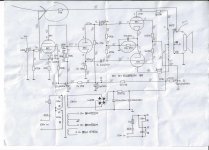
The kit came with no instructions whatsoever (they do say that), other than some pictures and the schematic drawing (attached). I assembled all the components on the PCB, PSU and all the in/out plugs.
Plugged it in for testing: isolation variac and current limiting (light bulb). Hooked up 8-Ohm dummies and started bringing it up slowly on the variac. Somewhere around 90V, I started hearing oscillation sweep coming from, I think, one (or more?) of the tubes… not sure which one(s). oscillations started at the low audible range around 250Hz, going up to 1-2K and staying there. Ran the same test with real speakers (which I very quickly regretted), and the same oscillation happened again, only mush lauder now. It kept doing the same thing at 110-117V.
Since then I have:
swapped tubes (as in the left ch set with right ch) - same results
replace all tubes with new ones – same results
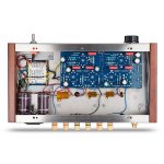
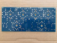
Decided to rebuild the thing, not using the PCB, as I thought it was poorly made and may have become microphonic or conductive or something, so I rebuild it point-to-point (I can read and follow schematics pretty well) using multiple star-ground points, and replacing many of the caps and resistors with better quality parts (at least that’s what I believe I did) – same results
third build – P2P & repositioning components & different grounding scheme: bus bar hitting chassis in one place only – again, same oscillations…
didn’t replace the irons, the rectifier and reservoir caps.
Not sure what the deal is, I doubt it could be poor design, as they are selling those things, and I don’t see any bad reviews about this product.
Another thing – as I said, I do have basic understanding of how this works, but I’m no expert, nor a designer, just “following the plan”. However, I have compared this schematic with a few other PP designs, and although they are all different, some elements do repeat themselves. I’m not sure I understand the two res and cap network that feeds into pin#9 of the 6F2 (36K; 82K; 100pF). I haven’t seen this anywhere else (yes, I realize there must be hundreds of designs out there, and no, I didn’t look at them all 😎), but – does this look genuine? I feel something is missing there, like a grid resistor, or a decoupling cap, or am I completely off?
Any input would be highly appreciated!
/DL
I’m new to the group and was wondering if anyone here could shed some light on a problem I’m having with this Chinese amp kit I am working on. I do have basic electronic knowledge and was building amps (solid state) and speakers many, many moons ago…. Now, returning to this hobby almost 30 years later, I am a bit rusty. Also, forgive the long-winded post.
No model number really, it goes by: “HiFi Class AB Tube Power Amplifier DIY Kit Push-pull Stereo Audio Amp 12W+12W”. from Doukstore.
Using 6F2 pentode-triode for pre and phase reverse, and two 6P1 (beam tetrode, as far as I know).
The kit came with no instructions whatsoever (they do say that), other than some pictures and the schematic drawing (attached). I assembled all the components on the PCB, PSU and all the in/out plugs.
Plugged it in for testing: isolation variac and current limiting (light bulb). Hooked up 8-Ohm dummies and started bringing it up slowly on the variac. Somewhere around 90V, I started hearing oscillation sweep coming from, I think, one (or more?) of the tubes… not sure which one(s). oscillations started at the low audible range around 250Hz, going up to 1-2K and staying there. Ran the same test with real speakers (which I very quickly regretted), and the same oscillation happened again, only mush lauder now. It kept doing the same thing at 110-117V.
Since then I have:
swapped tubes (as in the left ch set with right ch) - same results
replace all tubes with new ones – same results
Decided to rebuild the thing, not using the PCB, as I thought it was poorly made and may have become microphonic or conductive or something, so I rebuild it point-to-point (I can read and follow schematics pretty well) using multiple star-ground points, and replacing many of the caps and resistors with better quality parts (at least that’s what I believe I did) – same results
third build – P2P & repositioning components & different grounding scheme: bus bar hitting chassis in one place only – again, same oscillations…
didn’t replace the irons, the rectifier and reservoir caps.
Not sure what the deal is, I doubt it could be poor design, as they are selling those things, and I don’t see any bad reviews about this product.
Another thing – as I said, I do have basic understanding of how this works, but I’m no expert, nor a designer, just “following the plan”. However, I have compared this schematic with a few other PP designs, and although they are all different, some elements do repeat themselves. I’m not sure I understand the two res and cap network that feeds into pin#9 of the 6F2 (36K; 82K; 100pF). I haven’t seen this anywhere else (yes, I realize there must be hundreds of designs out there, and no, I didn’t look at them all 😎), but – does this look genuine? I feel something is missing there, like a grid resistor, or a decoupling cap, or am I completely off?
Any input would be highly appreciated!
/DL
Attachments
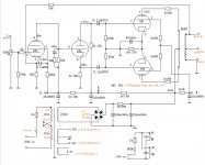

The schematic shows the recitifer bridge wired incorrectly - positive to ground and negative to B+. Did you wire it that way?
I missed that! But at worst there would have been a big bang as the electrolytics blew up in the PSU, at best there would be no plate current, no oscillation and no sound.
Have you tried swapping the output tube plate leads? Sounds like you have positive rather than negative feedback, doing so should fix the problem if this is the case.
I'll give that a shot. Just so I'm clear - swap the plate lead from 6P1-a with 6P1-b? The OPT is color coded, but I don't believe they designated which color goes to which tube.
Thx much!
The schematic shows the recitifer bridge wired incorrectly - positive to ground and negative to B+. Did you wire it that way?
Yes, I saw that. I have it wired correctly, plus to plus, minus to grd.
thx anyway!
Fairly bog standard circuit with feedback.
Only clanger I see is bridge rectifier is drawn wrong with positive output to ground and negative output to positive of smoothing caps.
I can only guess this is corrected on the real pcb ? otherwise caps would probably explode and/or blow fuse.
Sorry someone beat me to it !
Only clanger I see is bridge rectifier is drawn wrong with positive output to ground and negative output to positive of smoothing caps.
I can only guess this is corrected on the real pcb ? otherwise caps would probably explode and/or blow fuse.
Sorry someone beat me to it !
+1Have you tried swapping the output tube plate leads? Sounds like you have positive rather than negative feedback, doing so should fix the problem if this is the case.
I'll give that a shot. Just so I'm clear - swap the plate lead from 6P1-a with 6P1-b? The OPT is color coded, but I don't believe they designated which color goes to which tube.
Thx much!
That was it! Swapped the leads and VOILA! no more oscillations. Plays quite nice too. Very detailed. The speakers I'm using are not that great, lacks bass definition. Oh well, it is getting warmer outside, so I can now get back in my garage and start working on my next project - build some good quality speakers for this puppy.
Thx again man!
/DL

DL-
I built the same amp, had same issue at first. This forum helped me too w/ same advise on feedback issue. Youre right, the schematic doesn't show which output trans color wire goes to the 10k feedback res.
Jim
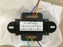
... which tells me that the PCB is misprinted... P1 (blue lead) should be going to P2 on the PCB, and vice-versa....
Hi, dl1964.
Good to know that you resolved the oscillation problem. And thanks for schematics with element values.
I have ordered the same kit.
Initially, I want to mount elements on PCB. But after I found this thread, I thought about point-to-point.
Please share photos of your build.
Good to know that you resolved the oscillation problem. And thanks for schematics with element values.
I have ordered the same kit.
Initially, I want to mount elements on PCB. But after I found this thread, I thought about point-to-point.
Please share photos of your build.
The cathode voltage of the first stage seems very low to me with only 0.42 V. But it probably is not a typo because the cathode current can't be much higher than 2.1 mA (= 0.42 / 200) because if it would be higher, the voltage drop over the anode resistor becomes too large to fit with the indicated B+ of 278 V.
Is this low cathode voltage wise? I would think that some control grid current will flow (starts from about Vg1 = - 1.3 V and becomes larger when Vg1 goes more positive). Does 0.42 V provide enough room for the positive going parts of larger input voltages? I know that the global negative feedback has the effect that the input voltage can have a bit higher amplitude than 0.42 V before Vg1 = 0 V but still I wonder.
Is this low cathode voltage wise? I would think that some control grid current will flow (starts from about Vg1 = - 1.3 V and becomes larger when Vg1 goes more positive). Does 0.42 V provide enough room for the positive going parts of larger input voltages? I know that the global negative feedback has the effect that the input voltage can have a bit higher amplitude than 0.42 V before Vg1 = 0 V but still I wonder.
Last edited:
If 6F2 is indeed like ECF82 resistor values and operating point iare not right ... not a surprise from a chinese design 😀 .
The cathodyne has unequal 27K and 30K resistors ... distortions guaranteed
The cathodyne has unequal 27K and 30K resistors ... distortions guaranteed
Last edited:
I'll give that a shot. Just so I'm clear - swap the plate lead from 6P1-a with 6P1-b? The OPT is color coded, but I don't believe they designated which color goes to which tube.
Thx much!
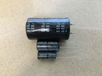
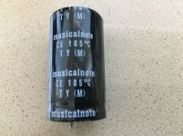
I just received the same amplifier kit today. The OPT does, in fact, have a sticker on the bottom designating the color and corresponding connection. I don't see any issues with the PCB, either. The only issue I've found is that one of the filter capacitors was a little squashed! That, plus the electrolytics aren't the best brands! Both filter caps are labeled "musicalnote". Seriously?!! They will all be replaced with corresponding Nichicon caps from Mouser. I also have a complete set of Russian tubes on the way, to replace the Chinese tubes. This should be a fun build!
Attachments

This is a good place to start imo, if you're new to building tube projects.
Many here design from scratch, or development programs, which is fine w/ considerable experience. Building tube projects presents danger of fatal shock not present w/ SS builds...so you have to 'train your brain' to think before you touch- even unplugged.
IMO- PCB designers should have put filament traces in, not requiring additional jumpers. Don't forget to ground the center tap of the 6F2 filament winding with supplied chassis mount copper tab.
I bought this same kit March of '20 from China vendor. My schematic doesn't have yellow english text shown on the OP's version- but does also show rectifier wired incorrectly- lol.
Since building original design, I've substituted in 3 others by mapping tube locations and designing PCB's to suit. Currently running Dynaco ST-35 / Pioneer SA-810 hybrid circuit. Experimenting was the best part of this process.
Have fun,
Jim
Attachments
In the above post, member oemcar says "Don't forget to ground the center tap of the 6F2 filament winding with supplied chassis mount copper tab." I sent him a PM to further explain the reason for doing this, but have yet to receive a response. Can anyone offer some information as to why this should be done...and also some detailed instruction as to what pins should be grounded? Are we only talking about the tube socket center lug, which isn't attached to anything? I don't quite understand what's going on here. Would greatly appreciate some help with this.
If the filament winding has a center tap , that should be connected to ground as he described .
If not , the usual method , 2 x 100ohm resistors from each filament winding ends to ground .
"Poor man's " method , one filament end to ground , doesn't matter if it's pin 4 or 5 at the socket .
Improved method , elevated filament potential .
If not , the usual method , 2 x 100ohm resistors from each filament winding ends to ground .
"Poor man's " method , one filament end to ground , doesn't matter if it's pin 4 or 5 at the socket .
Improved method , elevated filament potential .
- Home
- Amplifiers
- Tubes / Valves
- Problems with Chinese PP kit