I have just ordered one of these amps to go with a old valve pre-amp and turntable. I am 70 now, and started work in the late 1960's repairing radios and TVs in South London, then moved to NZ. I am starting to build up some vinyl again, and decided I wanted valve sound back. Interesting discussions about this kit, so thanks for all the gotchas that you guys have found.
I am going to be adding a switched headphone output so I don't have to annoy the neighbours or my partner. It will probably take a month or 2 for the kit to arrive, but I will let this group know how I get on.
I am going to be adding a switched headphone output so I don't have to annoy the neighbours or my partner. It will probably take a month or 2 for the kit to arrive, but I will let this group know how I get on.
If you want to use it for headphone use have a look at attached schematic which was specifically designed for low impedance headphone and or speaker use. If you have high impedance headphones (300 - 600 ohms) then you can go another way glassware audio (John Brosky) has a PCB for using some double triodes in SRPP without output transformers. I bought one of his SRPP PCB's for another purpose and never used it.
EL506
Wairarapa
EL506
Wairarapa
Attachments
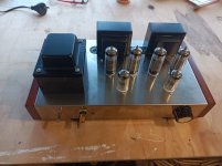
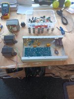
9 Days from shipping notification, and the kit was delivered. That is pretty unbelievable from China to New Zealand. So unpacked it and checked that all the components were there - just loose in a bag. The valves were well packed, in corrugated cardboard tubes, inside another tube. Put all the components on the circuit board, Drilled out the front panel for a headphone socket and switch. Installed the power transformer, power supply components and high power resistors. Then the input and output sockets, wired up the volume control (why is it linear?, they always used to be log pots). mounted that. Installed output transformers, then the circuit board. Connected up all the links, installed the dummy load for the headphones. Checked everything, then turned it on. Lots of heat, and HT sitting at about 200V instead of 300V. One channel working the other has hum and low power. Eventually removed the circuit board and found one resistor had a free end, no solder. Fixed that, put it all back together, and tested with a square wave. Both channels have the same output levels, square wave has a bit of overshoot, but I seem to remember that was normal with these amps. Plugged in the turntable, put on 50 year old version of The Who - "Who's Next". Sounded pretty good through some speakers, but way better through my Sony headphones. I am pretty happy with it (no mains hum, clear sound, slightly bassy through the headphones).
Attachments
Nice going! 🙂 The only parts I replaced were the input jacks. For me the volume pot has a nice range where I tend to have my listening volume, mainly music and occasionally movies.
I never use my amplifiers when I listen through headphones, only speakers. I have the sony wh-1000xm3 headphones, which are veeery bass heavy. Thinking about it I only use them for meetings at work. I have a pair of Klipsch RP-160m. They're not that fancy schmancy, but they sound good at the volumes I listen.
I never use my amplifiers when I listen through headphones, only speakers. I have the sony wh-1000xm3 headphones, which are veeery bass heavy. Thinking about it I only use them for meetings at work. I have a pair of Klipsch RP-160m. They're not that fancy schmancy, but they sound good at the volumes I listen.
It's a good place to start, given your desire to jump back in to tube equipment. I recall same issue w/ low HT B+. Power trans does run hot, but survived several months of use w/ 120VAC input. Guessing Chi's have sold quite a few of these kits... but not much on reviews of sound quality feedback here in the states-9 Days from shipping notification, and the kit was delivered. That is pretty unbelievable from China to New Zealand. So unpacked it and checked that all the components were there - just loose in a bag. The valves were well packed, in corrugated cardboard tubes, inside another tube. Put all the components on the circuit board, Drilled out the front panel for a headphone socket and switch. Installed the power transformer, power supply components and high power resistors. Then the input and output sockets, wired up the volume control (why is it linear?, they always used to be log pots). mounted that. Installed output transformers, then the circuit board. Connected up all the links, installed the dummy load for the headphones. Checked everything, then turned it on. Lots of heat, and HT sitting at about 200V instead of 300V. One channel working the other has hum and low power. Eventually removed the circuit board and found one resistor had a free end, no solder. Fixed that, put it all back together, and tested with a square wave. Both channels have the same output levels, square wave has a bit of overshoot, but I seem to remember that was normal with these amps. Plugged in the turntable, put on 50 year old version of The Who - "Who's Next". Sounded pretty good through some speakers, but way better through my Sony headphones. I am pretty happy with it (no mains hum, clear sound, slightly bassy through the headphones).
https://www.ebay.com/itm/133481896420?hash=item1f142419e4:g:PIQAAOSwANdiF6iA
I built same kit... for speaker use. Have had fun w/ it trying different designs within same chassis... welcome aboard :<)
Jim
I have this kit. I built the board but could not get the right channel working. I traced it out and it was printed wrong. The 470u50v / 10w 270ohm were connected to to pin 8 of the 6p1 tube.
I built it point to point but can't get the feed back loop to work correctly.
I built it point to point but can't get the feed back loop to work correctly.
That is affirmative. I just checked it againPC board trace was printed wrong on 1 channel only?
Why cant you just cut the trace going to pin 8 and reroute to pin 3? Is this the channel that is inop?
Why cant you just cut the trace going to pin 8 and reroute to pin 3? Is this the channel that is inop?
I could that but have already built it point to point. Just posting my problem in case anyone else is having same problem.
I'm glad that this thread is still moderately active. I just purchased this kit last fall, and while I have some experience with soldering and following diagrams, this project is really intimidating. Would anyone be willing/able to help me decipher the circuit diagram? I'm willing to pay for time spent tutoring.
I've build this kit and I seem to recal the schematics not matchning the board. However, the board is correct meaning if you place everything according to the component guidelines it works like a charm. You might wanna check the jacks as they are kind of crap. Good luckI'm glad that this thread is still moderately active. I just purchased this kit last fall, and while I have some experience with soldering and following diagrams, this project is really intimidating. Would anyone be willing/able to help me decipher the circuit diagram? I'm willing to pay for time spent tutoring.
What B+ is this kit runnning? I saw a couple of reports here of 200V B+, just wondering if that was the case for everyone?
Hey all, new to the group.
I picked up one of these kits as an intro to tube audio. I've done some solid state audio refurbs, and non-audio electronics builds, but am new to tubes.
I have the board assembled, following the labels on the board. I used Nichicon electrolytics to replace the off brand caps that came with the kit. Forgot to order Wimas to replace the supplied film caps, but can swap those later.
The layout seems slightly different from what's been posted previously.

Here's the supplied schematic:

The transformer is labeled for 120v, which is good (if true) considering previous posters appear to have units wound for 110v. Beyond that, things get a little weird.

For input they list red - black & red - black. Do I just bond the two blacks and two reds for input?
For output, they list green - green, which is fine. According to the schematic, these go to the rectifier. But there's an unlisted yellow/green wire also.
Next on the label is yellow - black - yellow at 3.15v - 0 - 3.15v. Not sure what happens with these. Would seem to be for heaters, but not enough voltage? Schematic shows the black wire as being grounded?
Last on the label is Black/Black at 6.3v, which would be used for the tube heaters, but these wires don't exist.
Any insight/suggestions are greatly appreciated. Thanks!
I picked up one of these kits as an intro to tube audio. I've done some solid state audio refurbs, and non-audio electronics builds, but am new to tubes.
I have the board assembled, following the labels on the board. I used Nichicon electrolytics to replace the off brand caps that came with the kit. Forgot to order Wimas to replace the supplied film caps, but can swap those later.
The layout seems slightly different from what's been posted previously.
Here's the supplied schematic:
The transformer is labeled for 120v, which is good (if true) considering previous posters appear to have units wound for 110v. Beyond that, things get a little weird.
For input they list red - black & red - black. Do I just bond the two blacks and two reds for input?
For output, they list green - green, which is fine. According to the schematic, these go to the rectifier. But there's an unlisted yellow/green wire also.
Next on the label is yellow - black - yellow at 3.15v - 0 - 3.15v. Not sure what happens with these. Would seem to be for heaters, but not enough voltage? Schematic shows the black wire as being grounded?
Last on the label is Black/Black at 6.3v, which would be used for the tube heaters, but these wires don't exist.
Any insight/suggestions are greatly appreciated. Thanks!
Yes , for 120V the two windings are in parallel , for 240V in seriesFor input they list red - black & red - black. Do I just bond the two blacks and two reds for input?
Between ends you have 2 x 3,15V for filaments , the middle tap 0 should be connected to ground.Next on the label is yellow - black - yellow at 3.15v - 0 - 3.15v. Not sure what happens with these. Would seem to be for heaters, but not enough voltage? Schematic shows the black wire as being grounded?
Mine is the same. The only diff from the schematic is there are 2 dc-blocking caps added on the input that are not shown on the schematic.The layout seems slightly different from what's been posted previously.
The green/yellow wire from the power tranny goes to a solid chassis earth.
My power tranny only has the yellow-black-yellow heater wires (3.15V x 2 = 6.3V) so I used those for all heaters and no prob. Just check your heater voltage when you first power it up to make sure its in spec.
Its a great little amp, one of my favourites, it has very good detail. I didn't connect the negative feedback. Mine runs pretty hot and I added a fan and vent holes in the sides for peace of mind. I also added constant current sources for the output tubes same as the original Baby Huey amp. There's nothing wrong with the stock coupling capacitors IMO. The only caps I swapped out are the 4 x 470uF ones at the 6P1's cathodes, I used some cheap Rubycons as I had them on hand.
Thank you @liquidfuzz @Depanatoru @Ian444 for the insights. Wiring is now pretty much complete.
Does the circuit board ground get connected to the chassis? I have grounded the chassis to the power cord ground.
Does the circuit board ground get connected to the chassis? I have grounded the chassis to the power cord ground.
- Home
- Amplifiers
- Tubes / Valves
- Problems with Chinese PP kit