Yes , connect the chassis at the big 330uF minus . Of course the circuit board is connected there too .
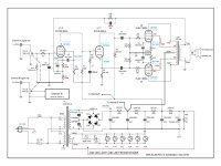
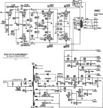
Attached is schema from April '20-
Per the comparison to Post #56, PT in my diagram shows (2) 6.3V windings. That matches your PT label. Post #57 is correct w/ wiring advice- imo.
As you can tell by the markings- I double checked my PCB per supplied diagram. Found pin #2 of the 6P1's was actually PCB traced to pin #9.
Initially thought this was mistake either diagram or PCB. Research showed 6P1 had internal connection from #2 to #9. Would have been nice if that were noted.
Jim
ps. It's good place to start- but there are so, so many better designs out there
Attachments

The red light district is another venue- lol
Both other options are good to try, however- After listening to that brick- I thot it sounded flat- imo...
Path was to map out the tube locations from the ChiFi chassis and create/try from what I had learned here
So- Decided first change to the.. Well- easier to see as line items-
1. Audionote ANK EL84 (Rev D or E)
2. Dynaco SCA35
Then design epiphany occurred- I found noise floor was way lower with a triode preamp compared to pentode-
Next level-
1. Dynaco ST-35
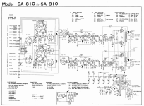
2. Pioneer SA-810 / ST35 Hybrid- the current
Latter combines the lo noise floor of triode front end w/ the bigger output plates of the 6GM5/ 7591
Rocks the house... This output stage is cleaner when leaned into v/ the 6BQ5 set. Thats my journey thus far...
Next level-
1. Eico 70 supermods PP quad
2. Frasier F106C 12GT5 quads 100WPC Barn burner
Depends on what your goals are...
Jim
Both other options are good to try, however- After listening to that brick- I thot it sounded flat- imo...
Path was to map out the tube locations from the ChiFi chassis and create/try from what I had learned here
So- Decided first change to the.. Well- easier to see as line items-
1. Audionote ANK EL84 (Rev D or E)
2. Dynaco SCA35
Then design epiphany occurred- I found noise floor was way lower with a triode preamp compared to pentode-
Next level-
1. Dynaco ST-35
2. Pioneer SA-810 / ST35 Hybrid- the current
Latter combines the lo noise floor of triode front end w/ the bigger output plates of the 6GM5/ 7591
Rocks the house... This output stage is cleaner when leaned into v/ the 6BQ5 set. Thats my journey thus far...
Next level-
1. Eico 70 supermods PP quad
2. Frasier F106C 12GT5 quads 100WPC Barn burner
Depends on what your goals are...
Jim
Attachments

Last edited:

Interesting journey you are on. I ran mine without negative feedback. Also CC's as mentioned earlier post. Equal concertina resistors. Added bleeder resistor on power supply caps. Zeners to reduce voltage to G2 on 6P1P. My best sounding small amp. For $200 USD from Icairn Audio store Aliexpress, hard to beat that value, as a DIY'er.
"I ran mine without negative feedback" - Tried changing the 10k FDBK resistor value, then deleting it- sounded raspy when deleted, all values in between were an inverse function. 10k was best balance per design
"Equal concertina resistors"- That seemed logical to me also- but there are varying schools of thought on that
"bleeder resistor on power supply caps"- Smart, very smart- so did I
"Zeners to reduce voltage to G2 on 6P1P"- Something I didn't consider trying 3 yrs ago- but seen that mod discussed here w/ other PP designs-
Not yet to the tuning procedures of my journey... first bring the boom- then refine the room-
Jim
Have mine assembled, added bleed resistors across the two filter caps.
Brought up on the variac with dummy loads, voltages measured ok.
Powered down and connected some sacrificial speakers and an input source as the next step. At power up it sounds good for a few seconds, then degrades into an increasing mess of distortion/oscillation? (not sure of the proper terminology to apply to what is coming out of the speakers).
This isn't affected by the volume control. It fades out once the power is cut, and the bleeders do their job.
Tried swapping the blue/yellow P1/P2 wires, but that was worse. Distortion mess immediately at power up.
Any ideas to troubleshoot this? Thanks again to all for the previous guidance.
P1/P2 is the primary of the output transformer ? Remove the negative feedback resistor 10K or the wire to it , from secondary to cathode of 6F2
And measure the voltages that are marked on schematic , this is for knowing if the board has no obvious mistakes / faults .
And measure the voltages that are marked on schematic , this is for knowing if the board has no obvious mistakes / faults .
@Depanatoru Thank you, that was it! Voltages were all over the place when wired with the neg feedback. I removed those connections and powered up. All voltages matched the schematic when running at 110V. No hum, no hiss, sounds good.
Yes P1/P2 are the output primaries, I have them connected as per the label on the bottom of the transformers. Blue to P1 and yellow to P2.
As an FYI for anyone who has one of these, or is considering one, my power transformer was marked as "120V" input, but that appears to be false. Running on my 122v house supply, the B+ measures 302v. Running from the variac at 110v, B+ is right at 278v as specified on the schematic.
Higher B+ is not an issue if the caps have enough voltage rating , the filament is important to be all the time below 6,3V so you don't "cook" the tubes and expect long life .
Negative feedback must be used , removing was for testing , so now that you know the amp is working fine you should figure out what was wrong when you use it .
Negative feedback must be used , removing was for testing , so now that you know the amp is working fine you should figure out what was wrong when you use it .
End beware , you must reverse the secondary for correct negative feedback .
You can't reverse the phase in the primary of a push-pull transformer because it is wired in such a way that the B+ central tap is one side of the winding and both the plate taps the other side . Obviously swapping the plates is useless , the result should be exactly the same .
You can't reverse the phase in the primary of a push-pull transformer because it is wired in such a way that the B+ central tap is one side of the winding and both the plate taps the other side . Obviously swapping the plates is useless , the result should be exactly the same .
Last edited:
@Depanatoru Thank you for the information. Sorry for my previous misunderstanding.
Yes the filament voltage is at 6.3v when running at 110v input.
For the output secondary, per schematic, we have an 8R(connected to neg feedback), 4R and common(connected to ground) taps. Which get reversed?
Yes the filament voltage is at 6.3v when running at 110v input.
For the output secondary, per schematic, we have an 8R(connected to neg feedback), 4R and common(connected to ground) taps. Which get reversed?
If you don't have negative feedback as it is , connect 8R to ground and 0 to negative feedback ... in this case they did a mistake and the secondary was wound in the opposite way that it should . For speakers doesn't matter anyway , connect them as usual , even if you use the 4ohm tap .
@Depanatoru That looks to be the issue. Secondary 8 & 0 leads are now swapped. Negative feedback now connected and sounding good. Thank you!
who would like try to EL84 / 6BQ5 / 6P14P, here is a pin comparison:
the 6p1p-ev is not a direct replacement of the el84, another pinout !
they are russian tubes, inscribed in cyrillic. imprint 6П1Р-ЕВ

the 6p1p-ev is not a direct replacement of the el84, another pinout !
they are russian tubes, inscribed in cyrillic. imprint 6П1Р-ЕВ
Last edited:
6P1P-EV != 6P14P
pin numbering on 6P14P is
1 NC
2 g1
3 C, g3
4 filament
5 filament
6 NC
7 Plate
8 NC
9 g2
Just like EL84
It seems however to be slight differences in electrical parameters
pin numbering on 6P14P is
1 NC
2 g1
3 C, g3
4 filament
5 filament
6 NC
7 Plate
8 NC
9 g2
Just like EL84
It seems however to be slight differences in electrical parameters


I received pictures of the setup of the amplifier from Douk Audio. Apparently there were also PCBs with a layout error😱
and someone in the audiokarma.org forum measured the OPT, they probably actually have 8.2k!
https://audiokarma.org/forums/index...se-the-qqe03-tube.931782/page-2#post-16471921
I have now also ordered a DIY kit, 204 euros including shipping (only Germany) still on offer for 4 days -15%
https://www.ebay.de/itm/166294103457
Attachments
Last edited:
I found an Korean blog in which someone describes the construction of the amplifier using the hand-wiring method. is a lot of effort😱
https://blog.naver.com/tk1404/222460024521
https://blog.naver.com/tk1404/222461280786
By the way, shipping the kit to European countries costs less than 20 euros from the eBay dealer😎
https://blog.naver.com/tk1404/222460024521
https://blog.naver.com/tk1404/222461280786
By the way, shipping the kit to European countries costs less than 20 euros from the eBay dealer😎
I received the kit from eBay yesterday, partly a disaster:
Since the box was externally undamaged, I accepted it as is. Then I made the mistake of starting to assemble the components because the PCB and components were on top. When that was completed, the disaster began: power transformer (only 2x110V instead of 2x115V, 6.3V~ winding not available) and tube base not as shown in the eBay offer (with a center hole), electrolytic capacitors too large in diameter (risk of the insulation of the electrolytic capacitors burning through when soldering and this results in short circuits), pot connections totally bent, housing damaged (dent especially in the visible area due to insufficient protection of the heavy power transformer inside the box) and not deburred, sharp edges everywhere ---> risk of injury! No holes for air circulation like with his other kits, but by using other sockets (I really wanted to install LEDs) this is now possible.
Now I can mess with eBay because the seller only offered a discount of 8% and that's decidedly not enough for me!
- Home
- Amplifiers
- Tubes / Valves
- Problems with Chinese PP kit