Help beginner "understand" balanced

Hi,

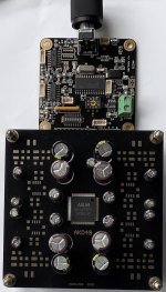
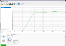
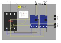
So I saw this image and it made me realise that I might not understand balanced, I just thought it separated the grounds so you could double the voltage and that was better for longer cables, resistance to interference and making (headphone) amps play louder (I think a power amp sort of "multiplies" sound, so say 2V x 10W is 20W then 4V x 10W is 40W I think this is probably way oversimplified).

Then it occurred to me (I was told that the analogue section of most DACs is what let them down) that a balanced DAC might have twice the (what I'll call) "bandwidth" like 4V means more "signal". I read 3dB more dynamic range. Do you get more "resolution"?

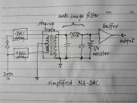
I also read some ladder DACs improve balanced, like maybe you can have more steps in your ladder?

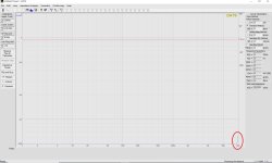
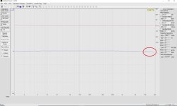
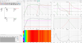
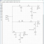
The CamillaDSP setup in the image is using two channels on a DAC changed into one channel balanced, is that going to "measure" better?

I was also chatting about (digital) volume and that you lose headroom, do you get more headroom with balanced, I have got to admit that I don't fully understand (a lot of advanced audio stuff including) headroom.

Can someone please sum things up for me?

Thanks.

1000000565.png

Music Hall A15.3 Blinking front panel LEDs

Evening,
Hoping someone on this forum has some experience with Music Hall a15.3. Bought it non-working, knowing it had one channel blown. But after removing and replacing the outputs (I replaced original 2SA1186/2SC2837 with 2SA1386/2SC3519 - which seemed like an exact match but with higher voltage and amperage ratings, albeit slightly slower at 30MHz vs 60MHz). I also tested all other transistors with the DMM and they checked out good. Compared resistors, capacitors and diodes to each channel and those also checked out good.

Symptom(s) ---
Powering on the unit you can hear the two relays "click" but about 5 seconds later, you hear a third relay "click" on the input section and the front panel LEDs start blinking (tried to show in pictures below)
1) first pic is on power-up, volume control and selected input LEDs light up
2) after about 5 seconds from relays clicking in, all the front panel LEDs light up
3) all the front panel LEDs continue to flash every second until you turn the power off (powering up again, starts this process over again)

I cannot find anything wrong with either power amplifier section - both have about 15mV of bias, pre-drivers get warm (maybe 90-degree F) but nothing too hot to touch comfortably. I also get 12mV and 9mV DC on the outputs - so it doesn't appear to be amplifier related due to protection kicking in.

I get all the low voltages as listed on the board +/-45V, +/-15V, +5V and +9V. Gone through the entire board checking resistors, diodes and capacitors and I have not found anything out of spec. (anything suspect, has been removed and tested out of circuit - with all testing good and soldered back in)

Anything you could suggest I try, or might know as a problem on these integrated amplifiers? I have had this sitting around for 2-3 months, working on it off and on - generally getting frustrated because I can't seem to find a faulty part.

Could it be one of the input "chips" or maybe the front panel "chip"? Not the best at reading a datasheet and circuit design and knowing how to confirm if it's working. I did check all the resistors and capacitors on the front panel and they seem in good working order and all measurements seem logical.

Could not find a schematic, so if someone has one would appreciate you sharing it with me.

Attachments

  • Pic 1.jpg
    Pic 1.jpg
    401.5 KB · Views: 121
  • Pic 2.jpg
    Pic 2.jpg
    422 KB · Views: 113
  • Pic 3.jpg
    Pic 3.jpg
    448.7 KB · Views: 115
  • overhead.jpg
    overhead.jpg
    727.2 KB · Views: 103
  • Right Channel.jpg
    Right Channel.jpg
    614.4 KB · Views: 95
  • Left Channel.jpg
    Left Channel.jpg
    600.3 KB · Views: 99
  • Front Panel connections.jpg
    Front Panel connections.jpg
    579.6 KB · Views: 103
  • Low Voltage Section.jpg
    Low Voltage Section.jpg
    604.6 KB · Views: 100
  • Inputs outputs section.jpg
    Inputs outputs section.jpg
    646.9 KB · Views: 107

Grossly parallel multibit DAC adventures

During my development of TDA1387-based DACs I came to the tentative conclusion that fewer chips was generally better in SQ terms. That was based on experience that strongly hinted that the power supply was the limiting factor and that more chips meant heavier demands on the supply. I also found that more output current made an I/V stage (other than a purely passive one) harder to get sounding good.

The power supply sensitivity turned out to be in large degree dependent on the variation in output voltage at the DAC's current outputs - purely passive I/V usually has the largest output voltage variation, consequently the highest sensitivity to power supply rail noise. By 'noise' here I don't just mean random noise, normally load-induced (i.e. signal correlated) noise is a bigger influencer of SQ.

A 'lightbulb' moment came when I considered that a step-up transformer could be used to ensure a very low voltage variation at the DAC's output whilst still allowing a high enough I/V resistor to be used so as not to need a voltage gain stage to create a 2VRMS output signal. Use of a step-up transformer isn't new, Audio Note had a patent on it (now expired). What is new is using a high ratio step-up transformer in conjunction with a very large number of paralleled DAC chips - the parallel array allows an even smaller variation of DAC output voltage and hence lower power supply sensitivity.

I've attached an outline sketch of the arrangement. A large number of paralleled DACs generates a peak current in the region of a few tens of mA. The DAC arrays are arranged to generate that current in 'push-pull' mode (aka 'balanced') so that there isn't any need to block the DC through the trafo - the DC currents are applied out of phase and hence cancel within the core of the trafo. The secondary of the trafo has typically 100X the turns of the primary meaning the standard 2VRMS is generated directly from 20mV at the DAC and only needs filtering (to attenuate images) and buffering to create a low output impedance for driving cables and a power- or pre- amp.

From my earliest experiments with a step-up transformer, I found that the primary inductance is what creates the LF roll-off and that the usual core material I use (PC40) doesn't give enough inductance (or have high enough mu in other words) to give an optimized design. So I have moved over to using 10K material which has about 4X higher mu but a lower peak flux capability. There aren't too many forms of core that this 10K material turns up in (at least in off-the-shelf quantities) on Taobao, I have for my earliest public design settled on using EP17. The wish to create a fully balanced design means using two EP17s per channel, for a total of 4. Fortunately they're cheap to buy on Taobao, the main cost is going to be in the labour to wind them.

Gerbers are attached for a 36 DAC board - four of these are needed to feed into the 4 EP17 transformers so that the output created is 2VRMS across the I/V resistors. In the sketch the output filter's shown single-ended but for the first design I'm going balanced, necessitating doubling up on filter and buffers, leading to a transformer between the two phases for creating a single-ended output.

Attachments

  • Like
Reactions: head_unit

Repair parts for Fender woofer?

I have a cab that uses a pair of 15” Fender P.S. 15Bs. They’re quite nice and from what I know they’re made by Guass. Unfortunately one of the woofers has some pretty major coil rub so it needs a recone.

I’ve done many recones in the past so confident in the ability, but I want to make sure I get the right parts. It looks to have a 4” coil. I did some looking and I don’t know, can anyone point out the parts they’d use to rebuild this?
IMG_3343.jpeg

IMG_3344.jpeg

Thank you,
Dan

Dayton Audio DATS V3 calibration question

I just bought a new DATS V3.
After Test Leads Calibration and Impedance Calibration (with integrated 1k resistor) there is a small increase of the value of the Test Leads resistance around 20 kHz and small decrease of the value of the integrated 1k resistor around 20 kHz (see pictures).

Is this the expected result after the completed calibration ?

Thanks in advance for any advice.

Attachments

  • dats_v3_short.jpg
    dats_v3_short.jpg
    192.4 KB · Views: 117
  • dats_v3_1k.jpg
    dats_v3_1k.jpg
    182 KB · Views: 110

A boring 2 way build

Welcome to a super boring 2 way build

Well.... I have these Silver flutes laying around and decided to make a cheapo 2 way with them. They were originally meant for my car but wouldn't fit. Then I was going to throw them in the wife's car but.... also will not fit.

So screw it! Lets throw some more money into the pit in the form of a tweeter and some crossover components and see what happens.

I picked this Peerless tweeter to go with it. The built in waveguide lets me cross it quite low. Under 2k. This should, in theory, sound better that crossing it over inbetween 2-5k which, I am told, is not the best place to cross drivers since hearing is sensitive there. The waveguide puts the z offset of the tweeter mechanically close to the z offset of the woofer. I am going to test this to see how close they actually end up.

I'm going to throw a 0.4 cubic foot box at this and vent it. I will post the WinISD sim.

Just thought I'd share. I'll probably use these in my garage since both drivers have really good off axis specs.

Pretty simple, pretty boring, maybe they will sound pretty good.

Attachments

  • Screenshot 2024-09-03 151256.png
    Screenshot 2024-09-03 151256.png
    125.7 KB · Views: 299
  • Screenshot 2024-09-03 151206.png
    Screenshot 2024-09-03 151206.png
    143.7 KB · Views: 326
  • Screenshot 2024-09-03 144046.png
    Screenshot 2024-09-03 144046.png
    67.4 KB · Views: 291
  • Screenshot 2024-09-03 125247.png
    Screenshot 2024-09-03 125247.png
    58.9 KB · Views: 243
  • Screenshot 2024-09-03 124957.png
    Screenshot 2024-09-03 124957.png
    67.9 KB · Views: 206
  • Screenshot 2024-09-03 151843.png
    Screenshot 2024-09-03 151843.png
    20.9 KB · Views: 271

Rockford TM1000X5ad Schematic

Hey guys. This is a long shot - does anyone have a schematic for this TM1000X5ad amplifier? This is a marine amp that is still being produced so Rockford won’t give out any diagrams.

It came in with Q1 and Q10 (IRFB4115) short. I removed the whole side and I moved two over from the other side to fit one in each bank. When the amp powers up, the low side has a normal looking pattern but it appears there’s about 28V leaking into it. Also, when you flip the amp over, I have two fets (IRFR4510’s) hot and their associated output inductor is getting hot as well. These fets do not appear to be marked with any associated Q’s so it’s hard to describe it. It would be the upper left two when the amp is flipped over.

I can’t tell if this is a two part problem or if it’s all related. On the top side D2012 (BAV99 or A7) has low side oscillation on pins 1 and 3 but 28V on pin 2. On the other working side it has only 8V or so.

I’m starting to get stumped on this one. I’d like to get the Q10 and Q1’s gates cleaned up - I can’t find the drive circuit for it, it’s nearly impossible to trace it with everything black and covered in marine grade coating. And I’d like to find out why the two fets on the bottom are getting hot.
IMG_0786.jpeg

Attachments

  • IMG_0787.jpeg
    IMG_0787.jpeg
    424.5 KB · Views: 109
  • IMG_0788.jpeg
    IMG_0788.jpeg
    692.1 KB · Views: 128
  • IMG_0789.jpeg
    IMG_0789.jpeg
    564.1 KB · Views: 119
  • IMG_0805.JPEG
    IMG_0805.JPEG
    454.3 KB · Views: 118

PCM179x VCOM & IREF

I know, I know, the PCM1794A, PCM1798 and similar are wildly unfashionable at this point. That said, they're not terribly expensive, and are relatively easy to implement using hardware control. I'd like to see how much performance we can milk out of them.

Paul Frost over at the TI E2E forum shared a schematic approximating what the IREF and VCOM pins actually do. (Over here.) Here's the schematic; note that VREF1 and VCOM2 pins are not physically accessible on the chip

1727830536965.png


I've seen many projects where the IREF pin is fed by a CCS. It looks like this would more or less take the servo amp out of the equation; the CCS sets the current though the current mirror which biases the LTP CCSs which make up the output stage. This also aligns well with the projects I've read here: reducing R_IREF increases the ouput current and changes the voltage on the VCOM pin.

That said, I haven't seen any experiments where the VCOM pin is fed by an external voltage reference. I tried connecting a GLED431 reference from VCOM to VCC with a 4mA CCS from VCOM to ground. This also scales the output current, but the DAC seems to work well. There's nothing obviously wrong with the sound and measurements are comparable with to using a CCS on IREF and a large cap on VCOM (but not directly comparable as I haven't matched the levels at 0dBFS).

Would anyone have thoughts on the technical merits of either approach? I would assume that we could provide a higher quality offboard reference, but I think I'm missing some of the subtlety of the servo amp. What exactly is it servo-ing?

Diagnostic Help Needed - Don Sachs Preamp--Aikido/SP14 Circuit

Hi Everyone! I'm looking to see if I can't diagnose noise occurring in a Don Sachs vacuum tube preamplifier, which is based on an Aikido preamplifier circuit also used by Tubes4Hifi in its SP14 preamplifier.

Here's the scoop.

The preamplifier uses 4 6SN7 octal tubes, has dual mono regulated power supplies for each channel, for both B+ and filaments.

The Issue:
  1. Hum/buzz on left channel only; Right channel is nice and quiet.
  2. On startup, the hum is barely there if at all. Within a few minutes the hum comes on and grows in volume over time.
  3. Hum is not affected by: moving to different system, house, swapping new/different tubes, changing cables, removing other equipment, etc..
  4. Hum is present even with no source connected.
  5. Hum is present even if using power conditioners or not using them.
  6. I've disconnected everything and the hum is present (so long as an amplification source and loudspeaker are present on the left channel.
  7. The sound of the hum/noise oscillates a bit and sounds like a motor running and changing speed due to changes in power sent to it.
  8. It has grown over time (last month) to now it has to be addressed.

I emailed Don but he's doing a new thing now (no longer building these) and I did buy this preamp used. I know he said once that he recommends putting carbon film caps on the grids and cathodes for all 6sn7s, but I haven't inspected it that closely to know.

Here's a link to the SP14 schematic:
https://www.icloud.com/iclouddrive/0c1iv9KCt0l7X80KfV0UNxpEw#Public

I will take a photo tonight of the actual PCB in Don's amp to show where there are differences.

I opened the unit just to see if there was a cold solder or disconnected ground, etc. Everything is sturdy and sound (from observation with the eye). I haven't tested anything with my multimeter and I don't have other testing equipment.

My sense is there's some DC leaking in a capacitor or a failed resistor, but I'm not sure where to start. Maybe there's a ground loop, but I'm not seeing it with a naked eye.

Any help is super appreciated. If you're in the Chicagoland, NW Indiana, or SE WI area I'd pay you to consult!

Thank you!!!!

For Sale Brand New AE Acoustics Elegance TD15M Midrange Woofer Drivers

I have a total of 4 Brand New AE Acoustics Elegance TD15M Midrange Woofer Drivers For Sale. I am the original owner and purchased them directly from AE Speakers many years ago for my DIY Speakers.

But I didn't have time to start the project so they are Brand New unused and in perfect factory condition.

Price is $800 each from AE Speakers currently and you can make a fair offer.

I will ship them in the U.S.A with FedEx Ground insured only.

PayPal is the Preferred payment method but you must have a confirmed shipping address.

For Sale Tamura PC-3004 power transformer

Selling 1x Tamura PC-3004 power transformer, NIB

Prim : 0-100V
Sec : 400V-360V-0-120V-360V-400V (DC250mA), 6.3V-4V-0(3.6A), 6.3V-4V-0(3.6A), 5V(3.8A), 5V-4V-0(3A), 7.5V-5V-0(3A)

Including Tamradio top plate and screws

SOLD

Attachments

  • IMG_3719.jpeg
    IMG_3719.jpeg
    461 KB · Views: 175
  • IMG_3720.jpeg
    IMG_3720.jpeg
    461.3 KB · Views: 148
  • IMG_3717.jpg
    IMG_3717.jpg
    378.2 KB · Views: 122
  • IMG_3718.jpg
    IMG_3718.jpg
    384.9 KB · Views: 151

North Creek Okara II bookshelf speaker crossovers.

Hi, I built the North Creek Okara II speaker over a decade ago to replace my Lyn Olson Ariels. I keep all the crossover components. I currently use a cheap AliExpress 2nd order crossover on the Okara II. I was hoping somebody had an original crossover schematic for the Okara so I could use the parts I have on hand. I then plan on learning how to use the Xsim software to optimise the cabinets I built, as they have a different front baffle, which I designed to look similar to one of the Sonus GFaber designs!

QUAD 405 Clone wiring / ground loop

Hi everyone, I have 2 Quad 405 Clone boards which I would like to install in an aluminum housing.
1727615586397.png


I have wired the whole thing as shown in the picture,

1727616031498.jpeg


but I can hear a quiet hum on one channel. It is not loud and you have to get very close to the woofer to hear it, but it is audible.
I use the following switching power supply, it is a +- 40V (I know it is not 50, I will upgrade it later).
1727615693845.png

I have also tried to remove the ground loop breaker and connect PE directly to the GND of the SMPS, same behavior.
I am quite a novice when it comes to amplifier construction, so please point out the mistake.

Thanks

Attachments

  • 1727615621717.jpeg
    1727615621717.jpeg
    122.9 KB · Views: 123

A new, modern and user friendly speaker building website

Hei everyone! 😊

Too long; didn't read:I’m building a website to make DIY speaker design easier with features like build plans, calculators, 3D design help, and driver selection. Launching in 2 months—what top 5 features do you need most when building speakers? Let me know!

I hope you're all doing well! 😊 I wanted to share something I'm incredibly excited about, and I would love to hear your thoughts and feedback.

As an engineer and web developer who's always had a passion for DIY projects, I've spent countless hours building speakers over the years. One thing I've always thought about while working on my own builds is how amazing it would be to have an all-in-one tool that helps guide the design and building process from start to finish. A place where I could get help with calculations, design suggestions, and even visualize my speaker in 3D before ever cutting a piece of wood.

That's why I've decided to stop dreaming and start building a website that does exactly that! 🎉

My goal is to create a platform where anyone—from complete beginners to seasoned audiophiles—can easily design and build their own speakers, all with the help of integrated tools like:

• Build plans: Step-by-step guides to take you from concept to completion.

• Speaker calculators: Automatically handle the math behind speaker enclosures and ports.

• 3D design assistance: Visualize your speaker in 3D and adjust it as you go.

• Driver selection help: Get recommendations for drivers based on your design goals.

• And more...

The ultimate goal would be to have an integration with ChatGPT or similar, so you can get guidance throughout the whole process, going from an idea to build plans automagically through a simple conversation.

I’m planning to launch the first iteration of this website in a few months! But before I dive too deep into development, I want to make sure it’s as helpful and useful as possible.

So here’s where I need your help: What are the top 5 features you wish you had (or currently need) when building your own speakers? Whether it’s a tool you’ve always wanted or a problem you regularly face, I’d love to hear it!

Your feedback will be super valuable in shaping the platform, and I’d love to build something that truly meets the needs of the DIY speaker community.

Thanks so much for your time and input—I'm genuinely thrilled to see what we can create together. Let's make speaker building easier, more fun, and more accessible for everyone! 💡🔊


Cheers, Eirik

[Beginner] DSP XO calibration, how?

Hi,

I'm new to a lot of the "measurement" stuff, please be gentle!

So I want to build my first XO with CamillaDSP.

So I have a RPi5/DAC8X and I think I need a way to expose all eight DAC8X channels to the calibration Windows PC?

So perhaps can the USB UAC2 gadget expose them or does it max out at 2 channels?

I'm asking because from the limited info I can find online it looks like XO stuff in Audiolense XO needs access to the individual channels.

Or do I need 8 channels of USB DAC for testing, if so, thinking out loud, could I get four cheap 2 channel USB DACs, maybe PCM5102A DAC chips same as the DAC8X, it feels like this could cause "timing" issues though?

Could I use a 2 channel DAC and manually change cables when testing say the LR tweeters when testing stereo HF or the R mid to R tweeter when testing XO?

I do have an old MiniDSP U-DAC8 8-channel, not sure if it would be a mortal sin to use that for measurement? I also have a 4 channel UMC204HD.

Or am I barking up the wrong tree, I asked on the AudioLense XO forum but no reply yet.

Thanks!

Best software for PCB features for ESL?

Hi everyone !
i wanted to make a PCB ESL for a long long time, its just gone be mid/treble panel with some features to segment it later on (so divided by 3 for instance)... but i had problems with the only PCB software i know EasyEda (perfect for electronics, not for other things you can do with pcb), all pcb software is based on a schematic. parts etc and then make a pcb. i myself work in sketchup... yes old... and crap. but thats what i would like to use or something similar . any one has an idea of a piece of software where you can draw you panel (mostly holes and dictate where copper is gone be and where is not, double sides or preferred even 4 layers to encapsule the copper)
i ca import a DXF into easyeda, and make all circles a cut trough thats one step... but i want the copper not extend to the edge of the holes... and i would like if possible the copper to be embedded in layer 2 or 3.. so no painting or whatever is required.
does anyone have a idea what works simple and i can upload to JLCpcb for instance ? image is of an imported DXF in easy eda. but i dont know where to start. i dont want just holes...(i want the copper to be slightly bigger hole so it wont arc etc , and i want to make segmented parts... but not to sure how , since the PCB programs are mostly based on the schematic. instead of just drawing 🙂)
1727653632101.png

For Sale Pro Op-amps for op-amp rolling

Discrete Pro Op-amps, Big selection for op-amp rolling, for use in S500 preamps and other studio equipment, which only needs one op-amp.

There is only one of each, and they are clones of different famous op-amps that have been used over time. They have different sound signatures
and overdrive characteristics.

They are only sold as a complete batch with 10 pcs., that are:
  • Hairball Audio JE-990 (Jensen 990 klone),
  • Five Fish DOA 12 (?),
  • Five Fish DOA 17 (Melcor 1731 klone),
  • Iron Age M2 (Melcor 1731 klone),
  • Iron Age NV (Neve klone),
  • Iron Age NDOA (Neumann clone),
  • Iron Age QDOA (Quad Eight klone),
  • Iron Age FDOA (Flickinger 290-3 klone),
  • Iron Age ADOA (API 2590 klone) and
  • Iron Age JDOA (Jensen 918 klone).

Price pre payment including transportation to an EU country: Euro 375.

For Sale 15" woofers

Eminence DeltaLite 2515 II 15” Neodymium bass speakers, 8 ohms, very light weight.

They are used in some of Gravesens Open Baffle speaker projects, and they are also very good for subs or electric bass use.

New price is about Euro 400 for a set, without shipping.

I will ship to EU countries by pre payment for Euro 220 including shipping.

Attachments

  • Emi DeltaLite-1.jpg
    Emi DeltaLite-1.jpg
    103.6 KB · Views: 59
  • Emi DeltaLite-2.jpg
    Emi DeltaLite-2.jpg
    70 KB · Views: 58

ICEpower 700AS1 - how hot is to hot ?

Hello.
Those of you with a Icepower 700AS1: Hot hot are your heatsinks ?

I´ve got a Icepower 700AS1 up and running since 2 days.
Balanced input, driven by a SPL Volume 8, powering a 2*18" subwoofer (R DC = 2.7Ohm)
The heatsink HS1302 (the one next to the speaker output) gets quite hot.
Testsetup is on a flat board right now. Allround ventilation / free air / no case.

I know you can mount the heatsinks to the casing for heat dissipation. Which I will do lateron when putting it in a case.

Even with low power after a couple of minutes the heatsink HS1302 is getting very hot. I can only touch it for like 3 seconds, maybe 60°C I guess. Seems strange to me.
The amp works normal, protect LED is never on, its never shutting down, music sound real good.
The other two heatsinks on the board feel like 40°C.

I´m wodering if it´s normal for HS1302 to be "cooking" even with low power levels.

Before the 700AS1 the subwoofer was driven by Hypex FA251 or 501.
The plate of the Hypex Modules never got noticably warmer than body temperature.

What´s your experience with the 700AS1 ?
The 700AS1 shoudn´t be so hot with the same levels that the Hypex 251 handled while staying cold, should it ?

I have two Icepower 300AS1, those stay abolutely cold while playing music for several hours.

Cheers, Michael

Attachments

  • HEatsink 700AS1.jpg
    HEatsink 700AS1.jpg
    96.7 KB · Views: 114

Looking for Adam Audio T7V Power Supply Board schematic

Have a T7V >
Looking for Adam Audio T7V Power Supply Board schematic

Speaker not functioning

Does the monitor’s LED light up? No
Have you tried a different power source? Yes
Did you select the correct input at the back of the monitor? (RCA/XLR) Yes
Does the issue migrate to the partner monitor, after you swapped the audio cables between the two speakers? No


I'm not the original owner.
There is power coming into cream colored board but no power leaving. (red / black leads)
Thank you for your time
D

Amp crossover modification (Audison SRx-4)

Hi guys, long time lurker here. Am trying to modify an old audison amp (SRx-4 - the early model with the silver-and-blue color scheme) which has a rather narrow range of crossover frequencies, namely 50-220 Hz for LP and HP, offering the choice of HP for Channels A L/R and HP/LP for ChB L/R. I'd like to use it to actively drive my mid-woofers and tweeters separately using the active crossover, as I have another amp for the subwoofer. Which means, modifying that active crossover frequency - the later model of that amp has a "10x" switch which does change the filter range, something like that is what I want to do (although permanently).

Since I'm not that experienced with amp modification, I'd like to ask here first before making potentially money- or time-consuming mistakes. As I understand it (haven't been able to trace the dual-layer SMD PCB yet), the circuit resembles what is shown in Elliott Sound Products Project 148 - some variable resistors combined with a capacitor to set the filter frequency. So my approach would be to solder in new caps of much smaller size, basically going ~1/25th C to give me 25x the crossover frequencies (1200-5500Hz). I'm 99% sure the 56nF 100V caps here are the ones in the HP filter section, the sliders on the bottom of the image are the ones controlling the frequency. However since there are clearly lines going from the sliders to the set of 4 caps (82nF 63V types) on the bottom right of the image, I could easily imagine the 56nF being used in the high-pass sections, and the 82nF ones for the lowpass section (which doesn't quite explain why there are different values on these than on the others).

Does anyone have the schematics available? It's a bit of a daunting task to retrace this PCB for an amateur like me.
20240926_214241.jpg

Does anyone foresee any problems with replacing them with either 2.2nF film caps (~1/25th) for the 56nF ones, and 3.3nF for the 82nF caps?

Also, to protect the tweeters when driving them actively, would you guys recommend installing a large cap (basically a 6dB HP filter active below the working range, like 100uF~400Hz xo frequency), or does that seem like overly protective and not strictly necessary on a better-quality amp like the audison?

So thanks for reading through, looking forward to any replies!

3-Way Crossover Design - Method for adjusting XSim

Hello!

Could you guys comment on the methods I followed for the 3-way projects I use to build?

Along the last 2 decades, I've built some loudspeakers for my self, family and friends, all 3-way port based with extended bass response down to 30Hz at least.
Always "old style" relatively big (>60 liters) with 8" or 10" woofer, 4" mid range and 1" dome tweeter.
I've used to electrically model the speakers on Pspice (eletronic circuit emulator) to get an idea of the real impedance.
I have a reasonable knowleadge of analog eletronic circuits.
I've always started with a theoretical LR aligment frequency cuts and slopes crossover and adjusted the crossover elements based on the circuit emulation result.
After building the final box, lots of intuitive adjustments always needed to be done playing with resistors/inductors/capacitors.
I understand that the speaker modeling I used to do only models the "piston" range of the speaker and not the rolloff range.
I basically compared the loudspeaker with a headphone and adjusted the elements by ear with reasonable results, not intended to have high-end units.

Last month, I've got a calibrated mic and decided to rebuild the 3-way loudspeaker crossover of my own pair of loudspeakers using REW to generate frequency response and impedance files for each speaker already seated in the loudspeaker baffle. I've loaded the 6 files in XSim.
Starting with a theoretical LR 12dB/oct circuit, I've got the usual result with lots of deeps and peaks and cancelations between speakers , which I used to more or less resolve inverting polarities here and there intuitivelly. I know in LR, we should invert the polarity of just the mid-range speaker.

This time, playing freely with the inductors/capacitors/resistors in XSim, I ended up with a good result (for my standards) both in the XSim simulation as well as in REW real measurements at the first try. Took a lot of iterations, since I fixed a certain range and got troubled in others.

See the attached curves and schematic. These were indoor measurements at 25cm main axis, so disregard frequencies below 100Hz due to standing waves.

Just the tweeter frequency upper range didn't match much comparing simulation (XSim) and real measurement (REW).
I've made the adjustments (notch filter) for the real measurements, of course.
The only care I took was to observe the final minimum impedance (>4ohms) and the minimum frequency protection for the mid (>500Hz) and tweeter (>3kHz).
Looking at the schematic, it's completelly off from the theoretical LR aligment I've started with.
Mid-range ended up being just first order 6dB/oct with a notch to attenuate its breakup frequency peaks around 5 to 6kHz.
Woofer/tweeter 12dB/oct with a notch for the tweeter and a Zobel for the woofer.

Main question: what method you guys follow to adjust the crossover elements in XSim if the initial theoretical schematic doesn't get you a flat response at the first try?

Thank you!!

Attachments

  • REW_FR_25cm.jpg
    REW_FR_25cm.jpg
    166.3 KB · Views: 146
  • Xover_Schematic.jpg
    Xover_Schematic.jpg
    300.1 KB · Views: 139
  • XSim FR.jpg
    XSim FR.jpg
    138.7 KB · Views: 129

Series vs parallel filaments

I'm working on a design for a preamp with a phono stage. The phono stage is based on 2 EF40/86 and 2 5814A/12AU7 set up as amp -> RIAA -> amp -> cathode follower which then feeds into the main pre. The pre is all 12AU7s and 12AX7s. I'm running DC filaments across the board, so I settled on a parallel 12.6V to all tubes to reduce the current load on the regulators. Split supplies for the phono stage and the preamp stage. The issue is the two EF86 heaters at 6.3V each. My initial thought was to just run them in series, but after looking at some comments in other forum posts, there seems to be some concerns about heater mismatch and one tube pulling more current, so I thought I'd ask the hive mind.

Is there any way to balance the voltage across the two tubes? Virtual ground using 2 100R/5W power resistors? A current limiting resistor between the 2 filaments? Dropping resistors to turn the 12.6V to 6.3V (32R/2W)?

Any help would be appreciated!

Early schematic can be found here: https://www.diyaudio.com/community/threads/preamp-design-feedback.417521/
That thread apparently didn't get any traction. Probably the wrong forum section for that.....

Filament power supply below.

1727820213119.png


Thanks,
Chris

Parasound HCA-1205A help. What is this?

I am new here after lurking for years. I am making an attempt to rebuild one or both of my Parasound HCA-1205a. I have all the replacement caps on order as they are all leaking brown goo and the amps don't produce sound. As I was giving the individual amps a visual inspection, I noticed what I thought was a temperature sensor attached to the heat sink that also had the brown goo. This sensor is on Jumper 2, and the wiring diagram lists the part number as "TO-T95AR1U1" I can find no such part online. Anyway, the part has brown goo, but it may be adhesive. I am leaning away from that as it is in random places on all 5 of them. They are attached with a metal clip that screws into the heatsink, and thermal paste. I am attaching a few pictures.

Any thoughts on if these need replacing based on the brown stuff, and if so, what are they? Even Digikey tech support was stumped. Thanks

Attachments

  • 20241001_135324.jpg
    20241001_135324.jpg
    177.4 KB · Views: 81
  • 20241001_142507.jpg
    20241001_142507.jpg
    328.2 KB · Views: 84
  • 20241001_132451.jpg
    20241001_132451.jpg
    128.8 KB · Views: 84

Please help with DIY Subwoofer parameter

Hello, I am a complete beginner in speaker and amplifier schematics. I want to build a 6-inch down-firing subwoofer as a replacement for my old and worn-out 2.1 speaker subwoofer. For the L/R channels, I am using 4-ohm 2.75-inch 15-watt Harman Kardon full-range speakers and 1.5-inch 3-watt tweeters for treble.

Here are the parameters I am using and the design for the subwoofer:
-Box size: 25x25x25 cm made from 15mm MDF (30mm board at bottom for stronger driver mounting)
-Amplifier: ZK-TB21 TPA3116D2 Class D (32-pin original)
-Subwoofer driver: 6-inch Legacy LG 696-2 (parameters are attached)
-Ventilation port: 5 cm diameter with a 16 cm long port

There are a few questions I would like to ask, and I hope you can help me determine the answers:

1. How much power supply wattage do I need for this setup? Is using 19V 2.37A = 45 watts enough?
I have this adapter from an old Asus laptop charger with a DC port.

2. With these subwoofer specifications, is running at 2 Ohms better than 4 Ohms?

3. Is my box design suitable for achieving a soft and deep bass character? I will place the subwoofer under my computer desk.

4. My subwoofer box design is inspired by the Audioengine S8, but dimension-wise, I followed the Audioengine S6, which has a 6-inch driver and similar box dimensions around 25 cm. Is this good get smooth and deeper bass profile?

Good explanation really help me figuring this issue, thank you.

Attachments

  • IMG_20240929_113938_015.png
    IMG_20240929_113938_015.png
    105.8 KB · Views: 64
  • IMG_20240929_113938_467.png
    IMG_20240929_113938_467.png
    44.6 KB · Views: 60
  • IMG_20240929_113938_407.jpg
    IMG_20240929_113938_407.jpg
    117.7 KB · Views: 60
  • IMG_20240929_113938_834.png
    IMG_20240929_113938_834.png
    78.6 KB · Views: 54
  • IMG_20240929_113938_175.png
    IMG_20240929_113938_175.png
    106.1 KB · Views: 57

JBL L20 (European model) tweeter's crossover question

Hi All,

I just acquired a pair of JBL L20 (European model, made in Denmark), photo attached.
I would like to change the capacitors in the tweeter's crossover (schematics attached) to Jantzen capacitors but there are 2, C2 1uF in parallel with R1 3R9 resistor and C1 in series, now I want to use the Jantzen superior Z cap but the 6.8uf cost more than what I'm willing to spend so my idea is to get a 1uF superior Z cap and a Jantzen standard Z cap for the 6.8uF capacitor.
I would like to know please what's the reason for the 3R9 resistor in parallel with the 1uF cap?
why not just use 3R9 in series with 7.8uF (or 8uF) capacitor?

Thanks

Attachments

  • JBL L20.png
    JBL L20.png
    24.7 KB · Views: 162
  • JBL L20.jpg
    JBL L20.jpg
    57.2 KB · Views: 138

Question about Nobu Shishido 2A3 power supply...

Hello! I'm prepping for a build of this Nobu Shishido 2A3 DC amplifier. I should note that it's my second non-kit build... That said, I have a question about the power supply in the attached schematic and specifically why there is a 50 Ohm resistor before the first filter cap. From what I understand the first filter cap for a 5AR4 should be around 47uF. Is the 50 Ohm resistor serving as a buffer after the rectifier? Maybe I'm completely missing something obvious. Thanks in advance!

Screen Shot 2023-09-18 at 5.04.01 PM.png

Class D amplifier

Good evening,
I need help choosing a power amplifier for an all-in-one two-chassis system I'm building. In the lower section, I will include Teddy Pardo and Salas Shunt power supplies with Mundorf capacitors, while in the upper section I’ve already set up an R2R DAC with a discrete component output and the Buffer B1 preamplifier by Nelson Pass.
What kind of project could I use for the power amplifier? I will be using Harbeth M30 speakers, and I am intrigued by the Hypex ucd180hg hxr, but I am unsure if it is a good match or if there are better alternatives.
Thanks to anyone who can help!

Sony WMSP85 powers on but no sound

Hi everyone and thanks in advance for suggestions.

New to all this, so happy to accept any type of feedback.

I’ve purchased a faulty Sony WMSP85 active subwoofer. The unit powers on but no sound comes out.

I’d read on another thread that one of the ICs (STK-404-130S) fails very regularly, so I’ve desoldered that and replaced it to no avail.

I’ve also replaced 3 capacitors that looked like they’d burst, and I must confess I am probably responsible for some or all of these, because I think I created a short while voltage testing the old STK-404-130S.

When replacing the capacitors, I had come under the impression that the capacitance and type (film in this case) need to match however the voltage rating can be different, so long as it’s at least as high as the capacitor being replaced. Please correct me if I’m wrong on this. For reference, they were C203, C204 and C208 from the data sheet.

I’ve taken voltage readings across the PCB where the datasheet specifies the expected voltages, and they do seem to be a bit out.

The voltages across the STK-404-130S are as follows, with the data sheet expected voltage in brackets:

1: 0v (0)
2: 0.25v (0.3)
3: 0.14v (0.1)
4: 0.15v (0.1)
5: 0v (0)
6: -51.8v (-42)
7: 11.9v (12.3)
8: 0.64v (1.1)
9: -1.1v (-1.1)
10: -51.9v (-42.5)
11: 51.9v (42.5)
12: 0v (0)
13: 0v (0)


There’s 2 other smaller ICs (NJM4565DD), with voltages as follows:

IC202:
1: 40mv (0)
2: 40mv (0)
3: 23mv (0)
4: -11.9v (-12.3)
5: 5mv (0)
6: -1.8mv (0)
7: 11.6mv (0)
8: 11.97v (12.3)

IC203:
1: 5.8mv (0)
2: 5.9mv (0)
3: 5.2mv (0)
4: -11.94v (-12.3)
5: 34.2mv (0)
6: 35.3mv (0)
7: 35.6mv (0)
8: 11.93v (12.3)


The data sheet also has expected voltages for each of the 5 other transistors on the circuit, so I’ve tested these and they are as follows, again with expected voltage in brackets:

Q501
B: 0v (-3.8)
C: 0v (21.5)
E: 0.5v (not specified)

Q502
B: 0v (0.7)
C: 52.2v (1.3)
E: 0v (not specified)

Q503
B:0v (not specified)
C: 0v (21.5)
E: 0v (0)

Q504
B: 0v (0)
C: 0v (21.5)
E: 0v (not specified)

Q505
B: 0.25v (0.3)
C: 11.96v (12.3)
E: 0.014v (0)

Thanks for any input!
Cam.

Attachments

For Sale Markaudio Singles - Alpair 7A gen 3, 6P gen 2

Briefly mounted for testing and forgot about them. Will ship in factory box + whatever you are comfortable with, at actual cost, USPS only. Any reasonable offer for one or both.

Attachments

  • PXL_20241002_175858967.jpg
    PXL_20241002_175858967.jpg
    492.4 KB · Views: 41
  • PXL_20241002_175915737.jpg
    PXL_20241002_175915737.jpg
    175.9 KB · Views: 45
  • PXL_20241002_175936486.jpg
    PXL_20241002_175936486.jpg
    168.1 KB · Views: 38

Massive

This amp has no output.When I power it up the first time I saw oscillation on the high side but nothing on the low side.Now am not seeing no oscillation on the outputs.Rail and low voltages look ok.I didn’t spot any bad part yet.

Any suggestions?

Attachments

  • IMG_3893.jpeg
    IMG_3893.jpeg
    462.8 KB · Views: 84
  • IMG_3892.jpeg
    IMG_3892.jpeg
    739.9 KB · Views: 79

I'm in an internal space dilemma

I calculated a 30-liter box for my woofer, but the box will have 33 liters because of the internal box of the midrange that I will install. Doing the math here, the height of a round box for the midranger would be 35.7 cm, taking as a base the 4 inches that it has...
Therefore, the main box which would hold the woofer and the tweeter would have the measurements of Final Dimensions of the Box:
Height: 47 cm (0.47 m)
Width: 30 cm (0.30 m)
Depth: approximately 23.4 cm (0.234 m)
The height of the midranger box completely exceeds the depth of the box, and I wanted the speakers in the front to be arranged one above the other, as I think it is more aesthetically pleasing...
Any idea of how I can do this?
The midranger will operate between 400Hz and 3200Hz
I don't know if I should reduce the size of its box... for me, I think it's a great choice for it to be around 3 liters

Fixing two Nakamichi CD4 CD players, something interesting

I have with me two units of Nakamichi CD4. Bought next to nothing because one of them doesn’t work but the case is nice. This unit is 230V, no voltage selector
The other unit works (as claimed by seller) but the case is all rusted to heck. This unit has a voltage selector.
So we know they’re from different markets.

Opening both of them I realised not just the transformer side is different; the main boards are also different.
While the layouts are the generally the same, the components are different. And the 230V unit has all the components soldered willy nilly and canted as if rushed.

IMG_3803.jpeg

The multi voltage unit board with nice components

IMG_3802.jpeg

The 230v unit board with not so nice components.

On the multi voltage unit we can see near the analog out section, there are rows of green Nichicon Muse capacitors. The 230v unit only has two of them.

230v unit also has a mixed bag of capacitors from different brands. The four power supply caps has 2 different pairs but all four are 3300uf 25v.

C122 near spindle motor is orange which sticks out, probably a better (?) one since if it fails the cd will only spin half a rotation and stops.

This fault actually happened to the multi voltage unit and thankfully someone here pointed out in an old thread that replacing C122 will help with the spindle motor issue.

Multi voltage unit now runs well and my friend will be picking it up soon after I’m done testing (playing, hehe) with it.

The 230v unit is dead for the most part. No display, buttons do not respond. But the cd motor and tray does jerk a little when turned on so there’s something going on there.
Voltages seem correct and all semis tested ok on diode mode.

Pulling hair a little but that’s how it goes.

Oh yes I’m using the Nakamichi CD Player 4 service manual since I can’t find one for the CD4. Internals look the same when compared to the service manual.

**minor edits for clarification.

Tweeter Crossover Question

Hello,
ial
I am modifying my Spatial Audio M3 Turbo S speakers and would like a little crossover help. I used to modify and build speakers many years ago before software and DSP was even a thought. I added a horn and a SB Audience 65CDNT and and designing a new crossover for it to integrate this new driver and horn. I have the woofer figured out and am trying to integrate the tweeter. I currently have a contour circuit on the tweeter with a 2.2 uf cap and 10 ohm resister to bring down the horn rise to flatten the response. The compression driver in the horn starts rolling of at around 550 to 600 Hz which is good but a little to low to properly integrate with the woofers. When I try to install a cap on the tweeter before the contour circuit the added capacitor does not crossover the tweeter it just changes the contour circuit! How do I keep my contour circuit and add an additional crossover to the tweeter without either one being effected and letting me cross the tweeter over higher? I put a hand drawn diagram in this post to show what I mean.
1000005204.jpg

  • Locked
For Sale ACA MJ Racam pair UK

Pair of ACA Racams built with boards from Mark Johnson includes the heatsinks. Forget what I built with but think I used IRFP140s. Also a few mods added as per the ACA with premium parts thread. Running slightly higher bias than standard too.

Asking £75 plus postage

Attachments

  • IMG20240908125958.jpg
    IMG20240908125958.jpg
    293.1 KB · Views: 116
  • IMG20240908130013.jpg
    IMG20240908130013.jpg
    399.7 KB · Views: 109
  • IMG20240908130017.jpg
    IMG20240908130017.jpg
    329.1 KB · Views: 117

The human transistor tester

I am following this forum now for some time and I am amazed how many people with little or no knowledge or experience dare to open and work on discrete (that is with transistors) audio equipment.

When it comes to transistors many people can recognize it as a transistor but assessing if the part is not defective is more of a challenge. A happy few have a transistor tester and some even know how to interpret the readings.

If not, using a multimeter to measure the 2 diode junctions is not sufficient to assess the correct working. This method below I learned over 40 years ago and never failed on me.

  1. Connect the lead of your multimeter carrying the positive voltage to the collector and the negative to the emitter for an NPN transistor. The other way around for a PNP.
  2. The reading should be (close to) infinity for Si and "large" for Ge
  3. Moist the tip of your finger just a little bit. I say "moist", not "wet". Moist like you want to turn a page.
  4. Press your moisted finger against the collector and base
  5. The resistance reading should drop to a few hundreds or few tens of kilo ohms.
If you obeserve near infinity without touching the base, and a considerable drop while touching the collector and base, the transistor is good. As simple as that. If you want to double check, the resistance reading must be considerably less than touching the collector and emitter in the same way with the same finger.

Note on lead polarity: For analog, not-electronic multimeters the positive voltage is on the common (black lead). For digital multimeters I have no clue. I don't know if that is even consistent for all types. Just find out using a diode.

Note on Hfe: different transistor types have different Hfe. Small signal transistors like BC550 have quite some gain. So pressing on the lead ends might already give the reading. For larger transisitors like TIP42 you have to press on the flat sides of the wires. For TO3 transistors, put your entire finger tip on the housing and the base stud. That is why those large transistors came in that case: more area to put your finger during testing. Just kidding!

Note on collector and emitter leads. Fortunately there are 42 different standards for lead position on the various transistor housings. Transistors, especially small signal transistors have gain when you swap collector and emitter leads and do the described test. If you are not sure what is C and what is E, test the transistor in both ways. The measurement showing the highest gain has is connected correctly.

Note on meters: Analog meters are preferred over digital meters for this test and in general. Even the cheapest functional analog meter gives you better information about what you measure compared to digital. If this becomes a discussion, start a new thread.

For power transistors the Hfe is quite low. But because the collector current is also very low during testing generally Hfe > 10 and you will get a usable test reading.

Becker Radio CD Drive Mechanism Reverse Engineering

Hello,

I have BMW CD54 Professional Radios sitting around. For hobby project I dissembled one of it to see how it is working. I quickly realized that cd drive outputs audio to mainboard via I2S. There are 12 IO and power pins + 6 pin connector for I2S lines. Same Becker design used in different car brands as well, thats why I thought that if I can find out how is it working, it will be so easy to integrate an ESP32 for bluetooth music streaming.

I2S lines are connected to the SAA7325 however control lines and SAA7325 I2C lines are connected to the other proprietary Philips chip CM30430 that I cannot find the datasheet. So far the pinouts that I can traced are like this:

1693383184701.png


Do you have any suggestion for me to find out how the control working? Should I get an oscilloscope? I am adding CD Drive PCB and mainboard too.

1693383396512.jpeg

1693383378236.jpeg


1693383477050.png

Modification for: Nvarcher R2R DAC PCM61 Quad-Parallel Differential Design can it use PCM56P?

Product chars :

Input method: SPDIF & I2S

Support sampling rate: SPDIF 44.1khz 88.2khz 96khz 192khz

I2S:44.1khz~384khz

1727852405528.png


I`m trying to modify this board to accept pcm56, but without any success, as the datasheet states both dacs are pin compatible, but when trying direct swap, the pcm56p is playing music but with noise. Should I assume that the WM8805 is the main issue in this configuration or something else? Another question, can I use the I/Out of the pcm`s in parallel? Removing the single op amps and feeding to valve output?

Bohlender-Graebener RD-75 ribbons - 1 pair, in enclosure, RARE (Chicago)

The RD-75 is extremely rare, no longer in production. It is the late David Graebener’s “ultimate transducer” magnum opus. 88dB sensitivity, 100Hz-17KHz response; they combine incredibly low moving mass with the surface area of a 12” woofer and 200 watts power handling. They play very loud with no visible excursion, and have a light, transparent, fast sound with large presentation and big stereo image.

For 12 years these Bohlender-Graebener RD-75 ribbons were the centerpiece of my “Ultimate 2 Way System”.

These RD-75s are mounted in a closed-back box (monopole, not dipole). The speakers are in excellent condition, built in 2005. Well cared-for. The cabinet was custom made for me, matte black finish and has no significant scratches or blemishes. Baby grand piano not included 🙂

bohlender_graebener_9737+.jpeg
bohlender_graebener_9740+.jpeg
bohlender_graebener_9743+.jpeg
bohlender_graebener_9738+.jpeg


They need no crossover in the ultra-sensitive 2-5K region where the ear is most sensitive. This is why the sound is so top-to-bottom coherent.

These line-source handcrafted ribbon drivers deliver transparency, resolution, and transient ability. The proprietary RD-75 ribbon driver uses an ultra-lightweight aluminum foil diaphragm suspended between powerful neodymium magnets.

Properly integrated, the response is smooth and level everywhere throughout the room. You can stand up, sit down, or even lay on the floor, and sound is consistent everywhere. This design minimizes floor and ceiling reflections. As soon as your ear rises above 6 feet elevation, the high frequencies vanish. That’s because the ribbon emits a cylindrical wave that does not reach the ceiling. You clearly hear every layer of detail in the recording. Vocals are lush and full and transparent. Percussion has clarity and drive. Plucked strings are almost visceral, when they need to be.

One of the most remarkable aspects of the RD-75 is its ability to capture the attack and decay of musical notes with startling realism. The ribbon drivers' lightning-fast response, combined with their exceptional linearity, ensures that even the most dynamic passages are reproduced with effortless precision and authority.

Measurements and photos I took this morning:

bohlender-graebener ribbons average FR 3 positions.png

Above: Frequency response, several distances, on axis, left and right channels averaged together.

bohlender-graebener ribbons step.png

Above: Step response. Extremely clean with no phase reversals.

bohlender-graebener ribbons impulse.png

Above: Impulse response.

bohlender-graebener ribbons distortion.png

Above: 2nd and 3rd harmonic distortion.

bohlender-graebener ribbons phase.png

Above: Phase response, which is +/-30 degrees from 200Hz-15Khz. Unheard of.

bohlender-graebener ribbons FR LEFT+RIGHT.png

Above: left/right responses overlaid in real room. I'm 95% sure the differences below 500Hz are because of the different position of the speaker in the room, not differences between the drivers; which match to within 1dB for great imaging.

Impedance is 6 ohms, resistive and almost straight-line flat. Super easy to drive.

I used these in biamp configuration with active DSP crossovers. You can also use these with passive crossovers. If so, they need a notch filter to pad down the area around 5K. The schematic is online https://techtalk.parts-express.com/filedata/fetch?id=1317741

I recommend using them above 200Hz with 12dB/octave crossovers. I wrote up the system I used these with, you can read all about it here:

https://www.perrymarshall.com/articles/ultimate2way/

If you have a couple of subwoofers with good midrange response and a DSP, it's pretty easy to put together a fantastic sounding system that rivals commercial designs costing 10-20X the price. If you wish to use these dipole, you can take the backs off of the enclosures or take the RD-75’s out of the enclosures. Any mods are up to you.

As you can see from the article, I was easily able to attain near perfect frequency, impulse, step and phase response with a 2-way system - at listener position in a real room with no crossover voodoo (no exotic FIR filters, just standard 12dB slopes). Not easy to pull off with almost any other driver.

DIMENSIONS:
Main part of enclosure: 76.75H x 14"W x 5.5"D
Base: 18"W x 14"D

Price: $1950 OBO for the pair. Pick up from my home in Chicago. Estimated shipping (continental USA via truck, will take time to arrange): $1000.

bohlender_graebener_9748.jpeg

bohlender_graebener_9747.jpeg

bohlender_graebener_9746.jpeg


bohlender_graebener_9745.jpeg


bohlender_graebener_9744.jpeg


bohlender_graebener_9742.jpeg


bohlender_graebener_9739.jpeg


bohlender_graebener_9735.jpeg

bohlender_graebener_9734.jpeg

bohlender_graebener_9741.jpeg

6BM8 Mini-Amp

Here is my first attempt at a mini (actually an micro-amp) using the Russian equivalent of the 6BM8. I have an octet of tubes on the way, and a a pair of bitty output transformers in fab at Edcor. The boards are in process at PCBway. I plan to power the amp using a DC-DC converter run by a 12V, 3.5A switching adapter. The amp takes its inspiration right from the Sylvania data sheet, with the power pentode being running full tilt at its 7W dissipation rating. I am running the input triode at 1ma plate current with an LND150 current source load. This will go into a proletarian bud box (so not all that pretty), with transformers on the bottom to keep the thing from tipping over. They will drive a set of Klipsch speakers that are actually pretty efficient (they have no problem making lots of noise with the 20W/channel Class A amp currently driving them). The amp will get a full characterization on the bench for frequency response and gain-phase, as I have a gain-phase analyzer available at work that goes up to 5 MHz. The values on the output Zobel network will be adjusted so as to keep the output gain from going back up through 0dB (gain margin as well as phase margin).

Attachments

  • 6BM8_AMP_SCH.gif
    6BM8_AMP_SCH.gif
    40.7 KB · Views: 737

For Sale Wolverine and vFET

I have way too many amps. Willing to part with one of my wolverines. Its in 4U modushop, with massive external power supply. Its ef3-3. Perfect sound. I will not ship it, but i can deliver within 100 miles of metro DC area. Asking $2000.

Attachments

  • 20240904_080309.jpg
    20240904_080309.jpg
    275.5 KB · Views: 149
  • 20240904_080358.jpg
    20240904_080358.jpg
    339.9 KB · Views: 146
Projects by fanatics, for fanatics
Get answers and advice for everyone wanting to learn the art of audio.
Join the Community
507,482
Members
7,873,740
Messages

Filter

Forum Statistics

Threads
405,557
Messages
7,873,740
Members
507,482
Latest member
kuttisrank