Hello,
I have BMW CD54 Professional Radios sitting around. For hobby project I dissembled one of it to see how it is working. I quickly realized that cd drive outputs audio to mainboard via I2S. There are 12 IO and power pins + 6 pin connector for I2S lines. Same Becker design used in different car brands as well, thats why I thought that if I can find out how is it working, it will be so easy to integrate an ESP32 for bluetooth music streaming.
I2S lines are connected to the SAA7325 however control lines and SAA7325 I2C lines are connected to the other proprietary Philips chip CM30430 that I cannot find the datasheet. So far the pinouts that I can traced are like this:

Do you have any suggestion for me to find out how the control working? Should I get an oscilloscope? I am adding CD Drive PCB and mainboard too.


I have BMW CD54 Professional Radios sitting around. For hobby project I dissembled one of it to see how it is working. I quickly realized that cd drive outputs audio to mainboard via I2S. There are 12 IO and power pins + 6 pin connector for I2S lines. Same Becker design used in different car brands as well, thats why I thought that if I can find out how is it working, it will be so easy to integrate an ESP32 for bluetooth music streaming.
I2S lines are connected to the SAA7325 however control lines and SAA7325 I2C lines are connected to the other proprietary Philips chip CM30430 that I cannot find the datasheet. So far the pinouts that I can traced are like this:
Do you have any suggestion for me to find out how the control working? Should I get an oscilloscope? I am adding CD Drive PCB and mainboard too.
Hello @mbt28 and all others!
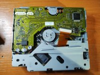
I found out that the CDM-M3 4.7/3 unit is used also in some Magneti Marelli navigation unit with the code name 156068727. I have two faulty cd drive units that I intend to repair. After inserting the disc, it just displays the message "CD-error" on the main unit. The center motor which is supposed to spin the disc does not rotate at all.
Please find attached a photo of the unit, to show that the PCB is very similar. It uses SAA7326, TDA7073AT, TZA1026T and the mysterious ASIC named Philips CM30430 with no datasheet. The info here is useful enough, but do you have anything that might be useful for repair? Schematics, tips, etc?
Lots of thanks,
Mihai
Attachments
Hello,
I checked a lot for CD mechanism's datasheet or service manual but I found nothing. I found correct pinout for the mechanism and It looks like it can be easily emulated by arduino.
I am busy with building my garage and house, when I have more time in the winter I will experiment more. With the help of a friend from another forum we already decoded the I2C logs for this CD mechanism.
Have you already checked both the focus and tracking coils and confirmed that the suspension for the focus hasn't sagged (a problem with some Sony mechanisms)?
@mbt28 Thank you for your reply. I will keep you updated with my progress in reverse-engineering the PCB. For me it will be ideally to find out what is not functional and eventually replace that part.
@Perry Babin I do not have a pinout for the laser/optical head, which is connected to the main unit via the 18 pin flex cable. If I find out where the tracking coils are connected, I will measure them. I cleaned the lens with isopropyl alcohol. Touching the lens with a soft cloth feels like it was moving enough, did not seem sagged.
@Perry Babin I do not have a pinout for the laser/optical head, which is connected to the main unit via the 18 pin flex cable. If I find out where the tracking coils are connected, I will measure them. I cleaned the lens with isopropyl alcohol. Touching the lens with a soft cloth feels like it was moving enough, did not seem sagged.
Hello again @mbt28 ,
Finally I managed to draw a proper schematic of the PCB in discussion. Please find it attached in pdf format.
It seems that there are two I2C interfaces on the boards. One is between the main unit connector and pins 13 & 14of the CM30430. The other one is between pins 15 and 16 of the CM20430 and the SAA7326. Could you please tell me for which one of these interfaces you managed to decode the I2C logs?
Maybe I could find the cause of the error by probing SCL and SDA with the oscilloscope/logic analyzer. I could decode the bitstream and compare it to your logs.
Best regards,
Mihai
Attachments
Hello all,
Attaching revision B of the schematic with a lot of corrected errors and omissions.
So far, I have managed to decode some of the instructions from the CM30430 microcontroller to the SAA7326. Mostly are "write servo commands", write parameter command A2 in hex according to the datasheet.
After a lot of these explanatory commands, it seems there is a pair of command which gets repeated infinitely: write servo A3 5F FF 00 hex, followed by read servo 55 hex. I did not manage to understand what do these ones mean exactly.
At startup the optical pickup head shows visible moving of the lens backward and forward for a couple of times, following the triangular actuation signal. The triangular drive signal on the oscilloscope shows the exact same pattern. The RA signal coil is not actuated, I do not understand what this does either.
However, the disc doesn't spin at all, although I have checked all drivers. The duty cycles on pins MOTO1 and MOTO2 does not change one versus the other, in order to drive the spinning motor.
I suspect that the focus procedure somehow fails. Therefore, the SAA7326 does not start spinning the disc. What are the reasons for the focus failing? Could there be some issues with the laser diode itself, so no valid signal on the RF output?
Attachments
After some tries, I have managed to repair a few of the units I had lying around. The conclusions are the following:
1. Although it is comfortable, you shouldn't try to probe signals with the unit sitting bottoms-up on your desk, with the PCB towards you. The CD motor cannot always spin the disc this way. Maybe it was not designed to run like this. You can solder long-enough wires on the visible testpoints and extend them outside the unit, and place it as usual, in the main unit frame, with the PCB towards the bottom.
2. I found that the optical unit is dead. Although the laser lights-up, (when filmed with a smartphone camera it shows a blue/white light), this does not necessary mean that the optical unit is working properly. The lens actuators (RA and FO) may function ok when tested (not sagged, as @Perry Babin suggested ), but there may still be an issue with the optical unit. If the optical unit is dead, the SAA7326 will power up the optical unit for approximately 2 seconds (LDON signal), but will not continue and therefore the disc will not spin. I have replaced the SF-C99 optical unit with another good one.
Finally, the disc spins and track information appears on the main unit's display. I have attached:
Hopefully someone working with this unit may find this information useful.
Regards,
Mihai
1. Although it is comfortable, you shouldn't try to probe signals with the unit sitting bottoms-up on your desk, with the PCB towards you. The CD motor cannot always spin the disc this way. Maybe it was not designed to run like this. You can solder long-enough wires on the visible testpoints and extend them outside the unit, and place it as usual, in the main unit frame, with the PCB towards the bottom.
2. I found that the optical unit is dead. Although the laser lights-up, (when filmed with a smartphone camera it shows a blue/white light), this does not necessary mean that the optical unit is working properly. The lens actuators (RA and FO) may function ok when tested (not sagged, as @Perry Babin suggested ), but there may still be an issue with the optical unit. If the optical unit is dead, the SAA7326 will power up the optical unit for approximately 2 seconds (LDON signal), but will not continue and therefore the disc will not spin. I have replaced the SF-C99 optical unit with another good one.
Finally, the disc spins and track information appears on the main unit's display. I have attached:
- the final revision version of the schematic (rev. C);
- one oscilloscope capture of the 4-wire interface signals between the CM30430 and SAA7326 (SCL, SDA, SILID and RAB which is always grounded). Here a write servo and read servo command are depicted;
- an oscilloscope capture of the RFEQO signal from the output of the TZA1026 amplifier, while reading an audio CD. This is how the signal should look like. If the optical head is not working properly, only a common-mode (DC) signal of approximately 1.6V will be there during enable.
Hopefully someone working with this unit may find this information useful.
Regards,
Mihai
Attachments


- Home
- General Interest
- Car Audio
- Becker Radio CD Drive Mechanism Reverse Engineering