Go Back   Home > Forums > Blogs

Old

X-reg voltage stabilizer LTSPICE file

Posted 15th March 2013 at 01:54 AM by rjm (RJM Audio Blog)
Updated 20th March 2013 at 01:47 AM by rjm

I did up the X-reg circuit in LTSpice.

Results shown below, together with the LTSpice .asc file you can use to play around with this yourself.

First attached image shows FFT for the rectified DC (green), reference voltage (red) and X-reg output (blue) for the designed-for 10 mA output (top) and a more punishing 100 mA (bottom).

Second image shows an LTSpice screengrab for the LT1086 with bypassed adj pin under comparable loading. Input voltage in blue, output in green. This is a reasonable approximation of a "good" IC regulator.

Last image shows a plot of the exported LTSpice FFT data for the X-reg and the LT1086-12V (Cin 1000uF, Cout 100uF) both at nominal currents of 10 mA. The LT1086-12V is a reasonable substitute for a generic LM7812, i.e. a "bad" IC regulator.

A typical op amp will have sufficient PSRR to mop of the residual noise from the bypassed LT1086. The fixed LT1086-12V, on the...
Attached Thumbnails
Click image for larger version

Name:	xreg 01.png
Views:	10671
Size:	104.8 KB
ID:	910   Click image for larger version

Name:	LT1086.png
Views:	2263
Size:	56.0 KB
ID:	912   Click image for larger version

Name:	Regulator Comparison.png
Views:	1081
Size:	50.4 KB
ID:	914  
Attached Files
File Type: zip xreg 01.zip (1.9 KB, 257 views)
rjm's Avatar
rjm
diyAudio Member
Views 4563 Comments 2 rjm is offline
Old

What is dynamics?

Posted 5th March 2013 at 03:02 AM by abraxalito
Updated 11th March 2013 at 06:35 AM by abraxalito

Fascinating discussion going on about the nature of 'dynamics' over on this thread : https://www.diyaudio.com/forums/multi...nger-what.html

Pano writes (post 1174):

There is a consistency across several decades and cultures that high efficiency speakers sound more dynamic than low efficiency. That's a common subjective assessment, so we might ask "why?"

I'm not going to chip in on that thread because I have bigger fish to fry, but ISTM they're all barking up the wrong tree. That's because the question itself isn't quite posed correctly even though its a great start. Nobody listens to speakers alone, they're always powered by amplifiers. The answer to dynamics lies in amplifiers, not speakers. Put another way 'Its the electronics, stupid!'.

Higher efficiency speakers tax amplifiers (here meaning their power supplies in the main) much less - so there's no way to do an apples-apples comparison...
Attached Thumbnails
Click image for larger version

Name:	nitro-psu-noise-6hexa.png
Views:	353
Size:	8.6 KB
ID:	909  
Attached Files
abraxalito's Avatar
diyAudio Member
Posted in Uncategorized
Views 1429 Comments 11 abraxalito is offline
Old

RIAA Equalization Curve

Posted 5th March 2013 at 02:51 AM by rjm (RJM Audio Blog)
Updated 5th March 2013 at 03:37 AM by rjm

For reference and experimentation.

This excel worksheet will provide you with reference data that you can overlay and compare with the measured/simulated response plots of actual phono stage circuits.
Attached Thumbnails
Click image for larger version

Name:	RIAA.png
Views:	3729
Size:	24.7 KB
ID:	907  
Attached Files
File Type: zip RIAA Standard Equalization Curve.zip (173.7 KB, 257 views)
rjm's Avatar
rjm
diyAudio Member
Posted in The Lab
Views 2638 Comments 0 rjm is offline
Old

6C33 OTL Fine tuning - BGs, ground and wire dressing

Posted 3rd March 2013 at 03:58 PM by wlowes
Updated 8th December 2014 at 01:39 AM by wlowes (Update - Bulk foil resistors)

The amps continued to run in and proved to be keepers. Well worth doing some final spit and polish. There was a little hum on one amp and some noise / hash on the tweeters of both channels. Nothing major, but certainly audible at 1 foot.
Using AC filament supply for all but the input tube, I figured I should re read the best practices on wire dressing, hum pots, virtual center tap etc.
Looking back there were some spots to improve.
1. tight wire twist on path from bridge rectifier to first caps. Done, no real change.
2. tight twist on b+ supply to input tube plus added BG 3uF 250v cap right at the tube. No change to noise but love the improvement in sound
3. tight wire twist from psu to b+ on all power tubes plus BG 10uF 250v on each power tube. Like the input tube the BG brought an immediate lowering of noise floor that really brought a finishing to the SQ. Quiet background, micro details and just a smooth rich sound. Not colored, just the way it...
Attached Thumbnails
Click image for larger version

Name:	6c33c optimization 002.jpg
Views:	1193
Size:	533.3 KB
ID:	890   Click image for larger version

Name:	6c33c optimization 001.jpg
Views:	1583
Size:	643.5 KB
ID:	891   Click image for larger version

Name:	POWER CONDITIONER THUMB.jpg
Views:	446
Size:	155.5 KB
ID:	1458   Click image for larger version

Name:	power conditioner jp.jpg
Views:	532
Size:	263.0 KB
ID:	1459  
Attached Files
wlowes's Avatar
diyAudio Member
Posted in Uncategorized
Views 1761 Comments 0 wlowes is offline
Old

The best sounding I/V resistor

Posted 3rd March 2013 at 10:22 AM by dvb projekt
Updated 30th November 2016 at 09:17 AM by dvb projekt

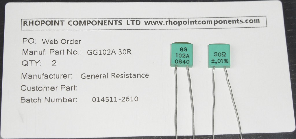
As many of you know, i am using the Texas Components TX2575 Bulk Z-Foil resistor for a long time
in important circuit positions, especially as I/V resistor.

Recently i stumbled over a short recommendation from Thorsten Loesch.


Quote:
Originally Posted by ThorstenL View Post
Hi,
I would second Rohpoint, Neohm less. Rohpoint are truely excellent. For my first TDA1541 Non-OS DAC (in 98) I handmade bifilar wound Non-inductive 25 Ohm resistors.
In susequent builds I compared to Rohpoint (which I have used extensively and found no reason to handwind resistors.

In my commercial designs we use a specfic type of SMD resistors after auditioning tons.
Some SMD resistors are really bad, some are so-so and some are most excellent, though no patch for a Rohpoint Squaristor GR102.

Ciao T

Because i know Thorsten as a man who had the perfect sound in mind,
i ordered one pair 30R to try them in my Tube-I-zator.


Click the image to open in full size.
...
dvb projekt's Avatar
diyAudio Member
Views 8167 Comments 16 dvb projekt is offline
Old

Line input RF reject filter

Posted 19th February 2013 at 08:24 AM by abraxalito
Updated 26th February 2013 at 04:09 AM by abraxalito (Added zoomed passband plot)

I've only simmed this so far, no listening tests. The aim here is to have a passive filter which works into a line level impedance (i.e. 10k or greater) and which gives a decent amount of RF rejection without compromising SQ. I plan to incorporate it behind the RCA input jacks of my chipamp.

Design-wise, it started life as a simple 2nd order filter with single series L and shunt C. But when it came to wind the inductor I didn't have a wire diameter small enough to make the required value (44mH). So I split up the inductor into 2 * 22mH and then couldn't resist hanging a cap off the centre tap. The result has turned more into an over-damped elliptic with a higher corner frequency than the original, but with an impeccable phase response to 20kHz. The elliptic-type plot comes about because of the SRF of the two inductors (around 350kHz).

Since fas42 remarked on the phase performance, I've added the group delay plot for the passband. Almost pure time delay of...
Attached Thumbnails
Click image for larger version

Name:	passive-line-input-filter.png
Views:	631
Size:	7.2 KB
ID:	878   Click image for larger version

Name:	passive-line-FR.png
Views:	364
Size:	5.3 KB
ID:	879   Click image for larger version

Name:	passive-line-input-zoomed.png
Views:	314
Size:	5.9 KB
ID:	880   Click image for larger version

Name:	28mH-chokes.png
Views:	514
Size:	338.7 KB
ID:	881  
Attached Files
abraxalito's Avatar
diyAudio Member
Posted in Power chip amps
Views 1967 Comments 8 abraxalito is offline
Old

FE126En Factory Reflex, a "cruel joke"

Posted 8th February 2013 at 09:14 PM by planet10

The subject of this box has come up before, after a 3rd reply to queries, this blog post,

Click the image to open in full size.

One of 2 Fostex factory recommended cabinets. 10.5 litre tuned to 61 Hz. The other is not very good either.

From the sims you can see that with this box any bass response you have will be way down which will exaggerate the FE126's forward midrange and the 7k peak.

Click the image to open in full size.

The top curve is half-space (ie what you would get if you mounted them flush in a wall or approximately what you would get with BSC added). The lower curve is with no filters and a simulated 6 dB of baffle loss. You would need a 2-stage filter to give any semblance of flat response. You would lose some 12 dB of sensitivity and then you run into the very low xMax which means that for...
planet10's Avatar
diyAudio Moderator
Posted in Uncategorized
Views 2439 Comments 0 planet10 is offline
Old

The Red Baron DAC Module V4.0 - Out of production

Posted 8th February 2013 at 09:34 AM by dvb projekt
Updated 30th November 2016 at 10:21 AM by dvb projekt

The Red Baron
V4.0


Click the image to open in full size.


The evolution brings the following changes

- Separate I2S-GND route to Digital-GND
- Separate Analog Output GND route
- Separate GND route for active divider decoupling caps to Analog-GND
- Modified active divider decoupling pads for better SMD 1210 caps soldering
- Onboard SOT353 footprint for fastest DEM-Synchronizer IC´s
- Un-interrupted ground plane
- MOSFET Source/Drain failure corrected


Still on the module

- Direct shunt voltage inputs with shortest onboard traces
- I2S In-/Outputs with shortest onboard traces
- I2S Attenuator and DEM Synchronizer
(by -ecdesigns-)
- Onboard Grounded-Gate MOSFET Current Buffer I/V Stage
(-ecdesigns- MK7 version)
- Separate GND-Trace for DEM-Synchroinizer
- Master/Slave
...
Attached Files
File Type: pdf Red Baron V4.0.pdf (593.7 KB, 1215 views)
File Type: zip TDA1541A Project - BOM - for The Red Baron V4.zip (9.3 KB, 809 views)
dvb projekt's Avatar
diyAudio Member
Views 3119 Comments 0 dvb projekt is offline
Old

Phonoclone boards, soldering, and Q1, Q2.

Posted 7th February 2013 at 06:34 AM by rjm (RJM Audio Blog)

This is in response to several recent emails I've received, where people were having problems with, typically, one board having a bad V+ or V- regulated voltage output.

The number of cases relative to the number of boards shipped caused me to worry that a manufacturing error might have occurred, so at my request I had a customer return the phonoclone boards he had built to me for inspection.

I'm happy to report that the problem was traced to poor soldering technique, the boards themselves are fine. What had happened was solder had cooled before the component had fully settled, and pushing the component down to the board surface then tore the trace away from the bottom of the board, breaking the circuit.

Subsequently, thinking the transistors blown, he replaced them, doing a fair bit of damage to the pads of Q1, Q2.

Fortunately, I was able to fairly quickly set everything to rights, and the boards are now on their way back to him....
rjm's Avatar
rjm
diyAudio Member
Views 819 Comments 2 rjm is offline
Old

Another Ikea Bowl Speaker

Posted 3rd February 2013 at 12:04 PM by googlyone

I stumbled on the people making speakers from the Ikea bowls. It kind of inspired me as the speakers were truly different and bizarre, but at the same time something completely different.

So I had to make some.

I fumbled around in the cupboard and came up with three choices of woofers that would do OK in a small enclosure - and after a few measurements and stuff settled on a pair of old Vifa M13SG-09-16 drivers. These were pretty well suited to an enclosure of a bit over 8 litres.

This drove me to the larger bowl, a 28cm one.

This is how they came out...

Click image for larger version

Name:	Speakers_Stands.jpg
Views:	3722
Size:	150.8 KB
ID:	872

To fit the driver I simply routed a rebate - and then cut the inside out.

Click image for larger version

Name:	Bowl_Router.jpg
Views:	2133
Size:	103.2 KB
ID:	864

The material of the bowl was quite thin once I had finished routing things - so I cut out a circle of ply and glued it to the inside of the bowl. I had to go out for the evening at that point so I simply...
Attached Thumbnails
Click image for larger version

Name:	Bowl_Outside.jpg
Views:	2216
Size:	122.0 KB
ID:	863   Click image for larger version

Name:	Hanging_Test.jpg
Views:	4599
Size:	98.9 KB
ID:	865   Click image for larger version

Name:	Ikea_bowl_rebated.jpg
Views:	977
Size:	137.1 KB
ID:	866   Click image for larger version

Name:	Pulse_Response.jpg
Views:	693
Size:	107.3 KB
ID:	867   Click image for larger version

Name:	Reinforcing.jpg
Views:	717
Size:	97.0 KB
ID:	868  

Click image for larger version

Name:	reinforcing_Inside.jpg
Views:	983
Size:	115.3 KB
ID:	869   Click image for larger version

Name:	Speaker_Stand.jpg
Views:	4193
Size:	107.5 KB
ID:	870   Click image for larger version

Name:	Speaker_Stand_Close.jpg
Views:	1639
Size:	149.2 KB
ID:	871  
Attached Files
diyAudio Member
Posted in Uncategorized
Views 6269 Comments 1 googlyone is offline

New To Site? Need Help?
Copyright ©1999-2017 diyAudio