Go Back   Home > Forums > Blogs

Old
Rating: 4 votes, 5.00 average.

PSU for High end audio without electrolytic capacitors

Posted 13th February 2010 at 06:18 PM by Nazar_lv (Creative High end audio)
Updated 1st April 2014 at 09:45 PM by Nazar_lv

From article https://s-audio.systems/diy/psu-without-electrolytic-eng
----------------------------------------------

Electrolytic capacitors are constant part of power supply of audio devices, but in terms of sound he does not bring anything good, dispersion of sound quality-type of electrolytic capacitor is very large. Sonically the best types of electrolytic caps are Nichicon KZ, FG, Panasonic Pureism, Black Gate FK, NX, Elna Cerafine, Silmic II, Silmic,but the attempt to eliminate from PSU electrolytic capacitors was very successful, instead is used "electronic capacitor" (right side of the circuit).
It is global negative feedback free electronic substitutes, that has a low and stable impedance 0,1...0,2Ohm (equivalent to cap 40000u) in the band to megahertz shunting NP0 0,1 microfarads Murata GRM31 in close to chips, it completely detach regulator (317\337) from load, therefore we have the ideal transient response when load "changes",...
Attached Thumbnails
Click image for larger version

Name:	capacitorless.GIF
Views:	16818
Size:	24.8 KB
ID:	113  
Nazar_lv's Avatar
diyAudio Member
Posted in Uncategorized
Views 19726 Comments 14 Nazar_lv is offline
Old
Rating: 2 votes, 5.00 average.

Synergy "Active" Crossover

Posted 6th April 2010 at 12:38 PM by wintermute (Wintermutes Rantings)
Updated 5th January 2011 at 03:18 AM by wintermute (fixed a couple of typos, and added a small amount of clarification.)

Following on from YARPS I thought I would post the design I have been working on for my active crossover (which is in fact is what the YARPS power supply was designed to drive).

So here I present the Synergy "Active" Crossover. Please note I have only simmed it at this stage (and when I started I knew nothing about active filter design) so there is no guarantee it will work.

Why have I put "Active" in quotes? Because whilst this filter uses active components, for all intents and purposes it behaves like a passive filter. It basically emulates either an LC or a CL passive 2nd order filter.

Why the name Synergy? Well I though it was the best word to describe the differing technologies working together to give the end result

The design goal is to have an active crossover that for all intents and purposes is transparent. That is it does nothing other than split the frequencies at the desired crossover point....
Attached Thumbnails
Click image for larger version

Name:	synergy.png
Views:	10392
Size:	19.8 KB
ID:	142   Click image for larger version

Name:	synergy_freq_resp.png
Views:	3077
Size:	18.5 KB
ID:	143  
Attached Files
File Type: zip synergy.zip (9.6 KB, 921 views)
wintermute's Avatar
diyAudio Moderator
Views 12148 Comments 12 wintermute is offline
Old
Rating: 2 votes, 5.00 average.

Demystifying the Cascode

Posted 14th May 2010 at 11:25 PM by Miles Prower
Updated 18th January 2017 at 06:22 AM by jazbo8 (replace missing images)

Basic Cascode

Click image for larger version

Name:	cascode.png
Views:	146
Size:	21.2 KB
ID:	2229

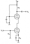
This is what the schemo of the cascode looks like. Rk serves to establish the Q-Point bias for the lower triode, and Rg is its DC grid return. Rp is the passive plate load. The voltage divider connected to the grid of the upper triode establishes its Q-Point bias.

So why would you want to do this? What you have here is a cascade of a grounded cathode stage driving a grounded grid stage. The GC topology has the advantage of a Hi-Z input. However, its high frequency performance is impacted by a high Cmiller that only grows worse with increasing voltage gain.

The GG topology avoids Cmiller for excellent high frequency performance, but it suffers from a Lo-Z input. It's not very often that a Lo-Z input is desirable. However, you can combine the two in a manner that work together. The Lo-Z of the GG stage loads down the plate of the GC stage, reducing its gain greatly. The lion's share of voltage...
Attached Thumbnails
Click image for larger version

Name:	cascode-ltp.jpg
Views:	192
Size:	13.2 KB
ID:	2230  
Attached Files
Miles Prower's Avatar
diyAudio Member
Posted in Uncategorized
Views 7448 Comments 3 Miles Prower is offline
Old
Rating: 3 votes, 5.00 average.

Salas HOT ROD DCB1

Posted 15th June 2010 at 03:56 PM by Tea-Bag
Updated 27th November 2014 at 04:51 PM by Tea-Bag (added BOM)

So I am going to write some details down about the DCB1 Hynotize Hot-Rod buffer. The current production board is black, 2 oz copper and 2mm thickness. (See below) The below blue pictures are prototype boards and are not representative of the product.

Here are some of the specifics to help understand ordering parts for it etc. This is not a detailed build guide, but there is a link to one below from another forum member.


Click the image to open in full size.

They can handle 10mm pitch snap-in capacitors 25mm width capacitors.

Click the image to open in full size.

There are positions for smaller MUR120 type diodes OR MUR820 style TO-220 style diodes. Not both!

The vRef LEDS can now be bypassed with a 25mm Film cap or a 100uf electrolytic. The film cap by consensus is best at .22uf.

Click the image to open in full size....
Attached Files
File Type: pdf Blue DCB1 v1.0.4.pdf (42.5 KB, 9329 views)
File Type: pdf SalasDCB1shuntreg build guide v4.1.pdf (50.7 KB, 9892 views)
File Type: pdf BOM DCB1 Oenboek.pdf (168.7 KB, 4235 views)
Tea-Bag's Avatar
diyAudio Member
Posted in Uncategorized
Views 33054 Comments 0 Tea-Bag is offline
Old
Rating: 3 votes, 5.00 average.

Don't be such a scientist!

Posted 15th June 2010 at 04:21 PM by jan.didden
Updated 15th June 2010 at 04:25 PM by jan.didden

I didn't get it. There are gifted design engineers on this forum. They get involved in threads. BUT, in most cases, eventually an 'issue' develops and the engineering guy gets binned or banned or asks to be banned. Why why why? Happened to me a few times. Not that I got banned, thank Ohm, but I got close to leaving because I too got enough of it.
Of what?
Let me explain. Most engineering types like to explain things, to tell others with less experience and knowledge what they are doing wrong and how they can do it better. They inundate you with facts, figures, links to engineering papers etc, and expect that the other guy flows over with gratitude. But, funny enough, it doesn't happen that way. The 'other guy' gets pissed off from being corrected all the time. Hell, he didn't come here for that, he came to have fun, discuss his hobby and his latest creation.

[flashback] At the time Al Gore's An inconvenient Truth came out, the same director (!) also made Too...
jan.didden's Avatar
diyAudio Member
Posted in Uncategorized
Views 9708 Comments 28 jan.didden is offline
Old
Rating: 2 votes, 5.00 average.

Basic common emitter amplifier design

Posted 28th August 2010 at 08:43 PM by wakibaki

The amplifier is probably the single most important composite circuit element in electronics. Certainly such familiar devices as radios and music systems would be impossible without amplifiers. The very large majority of amplifiers these days are solid state, that is, they use transistors. While there are many types of transistors, the first mass-produced transistors were BJTs, or bipolar junction transistors, and understanding transistor amplifiers, for most people, begins with these.

The transistor has three terminals and can be arranged in three basic amplifier configurations, the common emitter, common base (or grounded base) and common collector or emitter follower amplifiers.

Common base amplifiers are not commonly employed at lower frequencies as, amongst other reasons, they have a low input impedance, although they can be found in amplifiers for e.g. moving coil microphones. They are sometimes employed as current buffers, having a current gain of 1,...
Attached Thumbnails
Click image for larger version

Name:	common_emitter_3.jpg
Views:	5454
Size:	12.9 KB
ID:	237   Click image for larger version

Name:	common_emitter.jpg
Views:	3176
Size:	8.9 KB
ID:	238  
Attached Files
Banned
Posted in Uncategorized
Views 12060 Comments 0 wakibaki is offline
Old
Rating: 2 votes, 5.00 average.

PCBs for Dummies

Posted 19th February 2011 at 12:49 AM by NYCOne

WARNING:


The following method uses deadly, strong chemicals. Do not proceed as you could die, or lose a part of your body you value (eyes, face, hands, other). The following is for entertainment purposes ONLY. Following this method is taking extraordinary risk and you could get gravely injured, or die.

Yes, I was a dummy when it came to PCBs. In fact, I was a dummy when I came to anything DIY Audio a few months ago. Of course, now I’m an expert in all things.

All the information you could ever want is in the forum – “Just search the forum…”

It really irks me when people post that. “Hey, I already searched the forum, and now I’m asking…” As a newbie, I knew NOTHING about circuits, PCBs, soldering, resistors, you name it. I always wonder if the “experts” realize that new people enter the hobby now and again.

After trying lots of things, buying lots things, and running some experiments, I know a little bit about...
diyAudio Member
Posted in Uncategorized
Views 8914 Comments 5 NYCOne is offline
Old
Rating: 2 votes, 5.00 average.

Reference TDA1541A DAC Power Modules

Posted 7th April 2011 at 01:01 PM by dvb projekt
Updated 12th January 2017 at 10:19 AM by dvb projekt (Stock status updated)

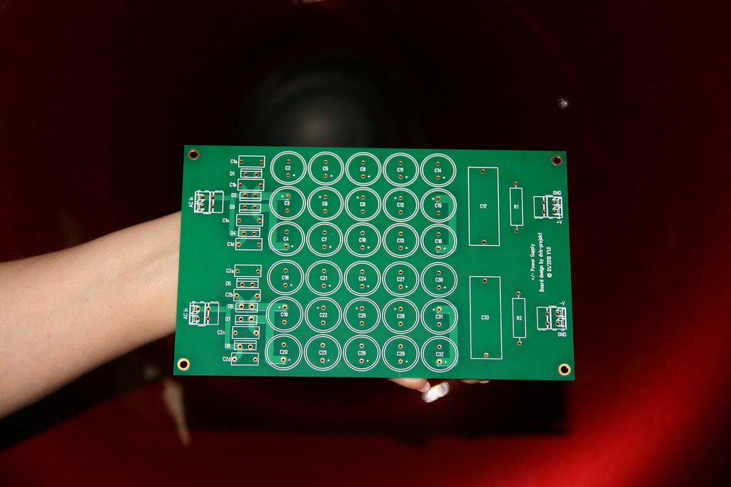
+/- Power Supply Module

Click the image to open in full size.


- up to 15 caps per rail (16mm to 18mm diameter)
- place for decoupling foil cap in each rail
- place for bleeder resistor
- 105µm copper weight
- 2mm pcb
- Immersion Gold
- green soldermask on both side
- Board size 195mm x 120mm

Sold out


Shunt regulator modules
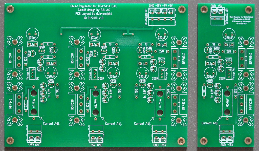
circuit design by Salas


Click the image to open in full size.

- Shunt regulator module for TDA1541A (+5V, -5V, -15V)
- separate Shunt regulator module for additional parts (+5V)
- 70µm copper weight
- 2mm pcb
- Immersion Gold
- green soldermask on both side
- Board size 147mm x 115mm (46mm x 115mm; single +5V)

TDA1541A shunt module 2pcs. left in stock
...
dvb projekt's Avatar
diyAudio Member
Posted in Offer
Views 9106 Comments 0 dvb projekt is offline
Old
Rating: 2 votes, 5.00 average.

Converting Eagle printed circuit board layout files to Gerber format

Posted 11th February 2012 at 12:20 AM by rjm (RJM Audio Blog)
Updated 29th January 2017 at 03:13 AM by rjm

File this under "things-I-should-have-learnt-to-do-many-years-ago-but-was-too-lazy-to-bother".

Many pcb fab outfits that do business with hobbyists and DIYers choose to accept Eagle .brd files, which means they do the conversion to Gerber output so you don't have to. I've relied on that for far too long, but when an error showed up in one the .pdf proofs on the last batch of boards I sent out for fabrication, they asked me to send the Gerber files instead. So I bit the bullet and after a couple of false starts managed to give them what they wanted. Looking back at it, it was easy and something I should have learnt, as I wrote up above, years ago, but, for posterity, here's how it's done:

Eagle 6 on Windows
  1. Make a working folder for the Gerber files.
  2. Copy the Eagle board (.brd) file to this directory.
  3. Open Eagle (version 6.1)
  4. Select menu item "file/open/CAM job"
  5. The open file dialog appears, defaulting to the Eagle CAM
...
rjm's Avatar
rjm
diyAudio Member
Views 8490 Comments 3 rjm is offline
Old
Rating: 4 votes, 5.00 average.

Advices for the new SIMetrix/SIMPLIX Intro users.

Posted 4th March 2012 at 06:37 AM by Alain Poitras (The SIMetrix/SIMPLIS Intro Spice Simulator)
Updated 16th March 2012 at 02:36 AM by Alain Poitras

Introduction

I am a steady user of the SIMetrix/SIMPLIS Intro Spice simulator and many peoples ask me how to use it. Because the same questions come back all the times and the answers often need to be quite elaborate and are time consuming, I decided to open a new Blog for this subject.

Since I am a member of this forum, I noticed there was thousands of threads and they often get loss very far from the first page after few days, where almost nobody can see them.

This is not the case with the blogs because there is not many yet on this site, also, it is possible to edit a blog anytime and not a post in a thread after 30 minutes ... This make corrections easy and I am not perfect, I often make some little or big mistakes.

I will not accept other members comments until the blog is almost terminated. Anybody having a request or a comment for me about this blog can send me private message, I will be glad to answer it and update my blog if...
Alain Poitras's Avatar
diyAudio Member
Views 7429 Comments 0 Alain Poitras is offline

New To Site? Need Help?
Copyright ©1999-2017 diyAudio