Posted 5th July 2017 at 06:12 PM byGrasso789 Updated 8th July 2017 at 09:22 PM byGrasso789
Class-D amplifiers are digital systems in the sense, that they have for one thing fixed band-width, say are sampling, and for another thing fixed Switching Range, say a least bit, belo which level they start to stay quieter than they should. In this paper I am only interested in the band-width issue, also for one may design a new digital recording system from scratch.
First to mention, in order to not obtain too much ringing and aliasing, sample rate must be at least 2*Pi*band-width. With band-width set to 16 KHz, I set sampling rate to 100 KHz. Most Class-D amplifiers have modulation frequency (resembling sampling rate) of 200 KHz or higher. Since raising sampling rate swells data or reduces Switching Range, I keep sampling rate as lo as sonically pleasingly possible, and that is 100 KHz.
The filter must put out at most -8 Bel-full-scale at 50 KHz, because I presume, that the following system will have only 10 Bel dynamic range or will not mind a few bits...
Posted 12th June 2017 at 06:25 AM bygooglyone Updated 12th June 2017 at 06:30 AM bygooglyone(errors!)
I finally got around to doing some measurements on the discrete op amp at G=2 and G=10.
These were non inverting mode - note the voltage was 6-8V p-p, and the rails were +/-15V so there was a fair whack of headroom. Anyway, I will let the measurements speak for themselves.
This is what they looked like...
I tested a whole bunch of configurations of the DOA, including:
Differential pair current 1, 1.5, 2 and 4mA
Output current 8mA (2* 4mA) and 12mA
VAS current 1.5, 3mA.
The test setup was a dual op amp board, one channel set to G=2 the second set to G=10.
The load for G=2 was 1kOhm. The load on G=10 was 10kOhm. I could go back and retest this... I had not lingered on this during the test.
The first challenge I found was MASSES of noise really messing with the results. It looked a lot like oscillation, and I kid you not, I spent hours trying...
Posted 11th June 2017 at 04:16 AM byalexcp (My DIY projects)
I built a headphone amplifier using John Broskie's Aikido All-in-One PCB with Tube Rectifier. The PCB is well made and easy to build, and I am satisfied with how it sounds.
One comment is that R9, R10, and R13 (see the attached schematic) affect the distortion introduced by the circuit. By changing R13, I was able to cut the distortion by as much as 90%, from 0.2% @1kHz 1Vrms output down to 0.02%. My optimum was R13=90ohm with B+ at 310V (using the recommended Hammond 270EX power transformer) and all other values as in the attached schematic.
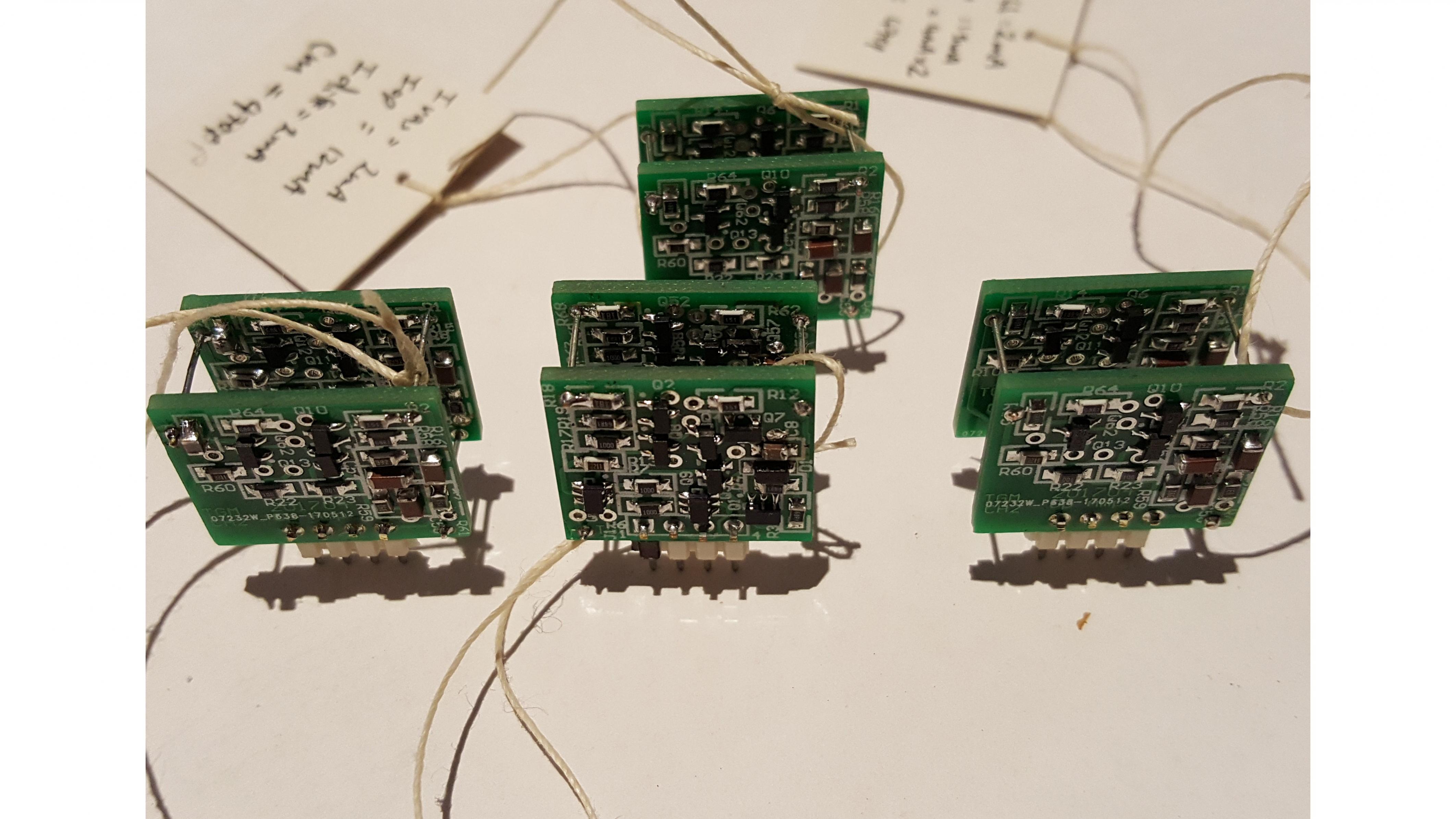
Well I am home again, and the PCBs for the discrete op amp beat me home.
I used PCBcart, who have a very competitive prototype PCB service -it is certainly not worth your time to make fiddly double sided boards like these at home!
They came out like this...
And no, I don't have a finger the size of a baguette...
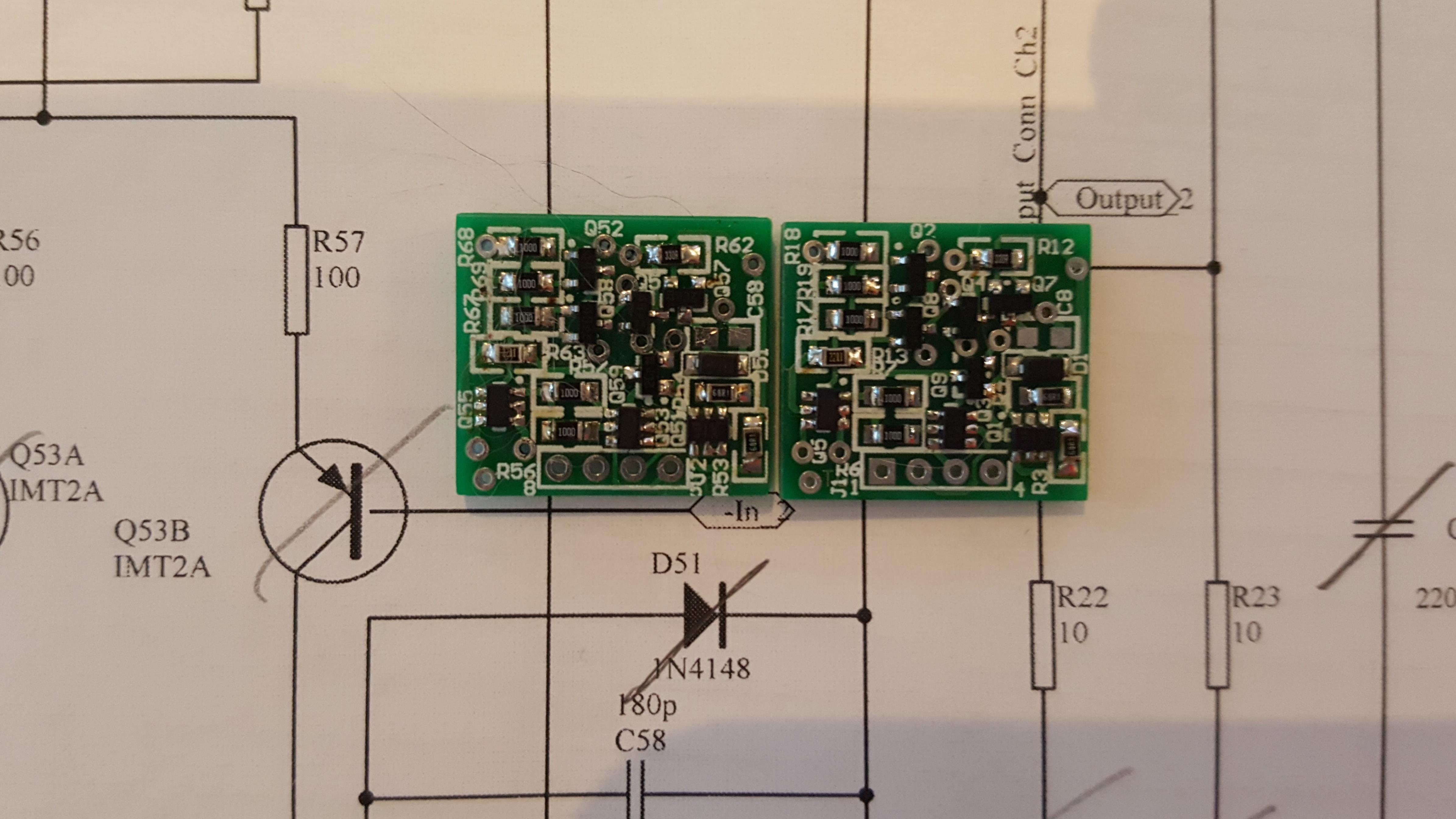
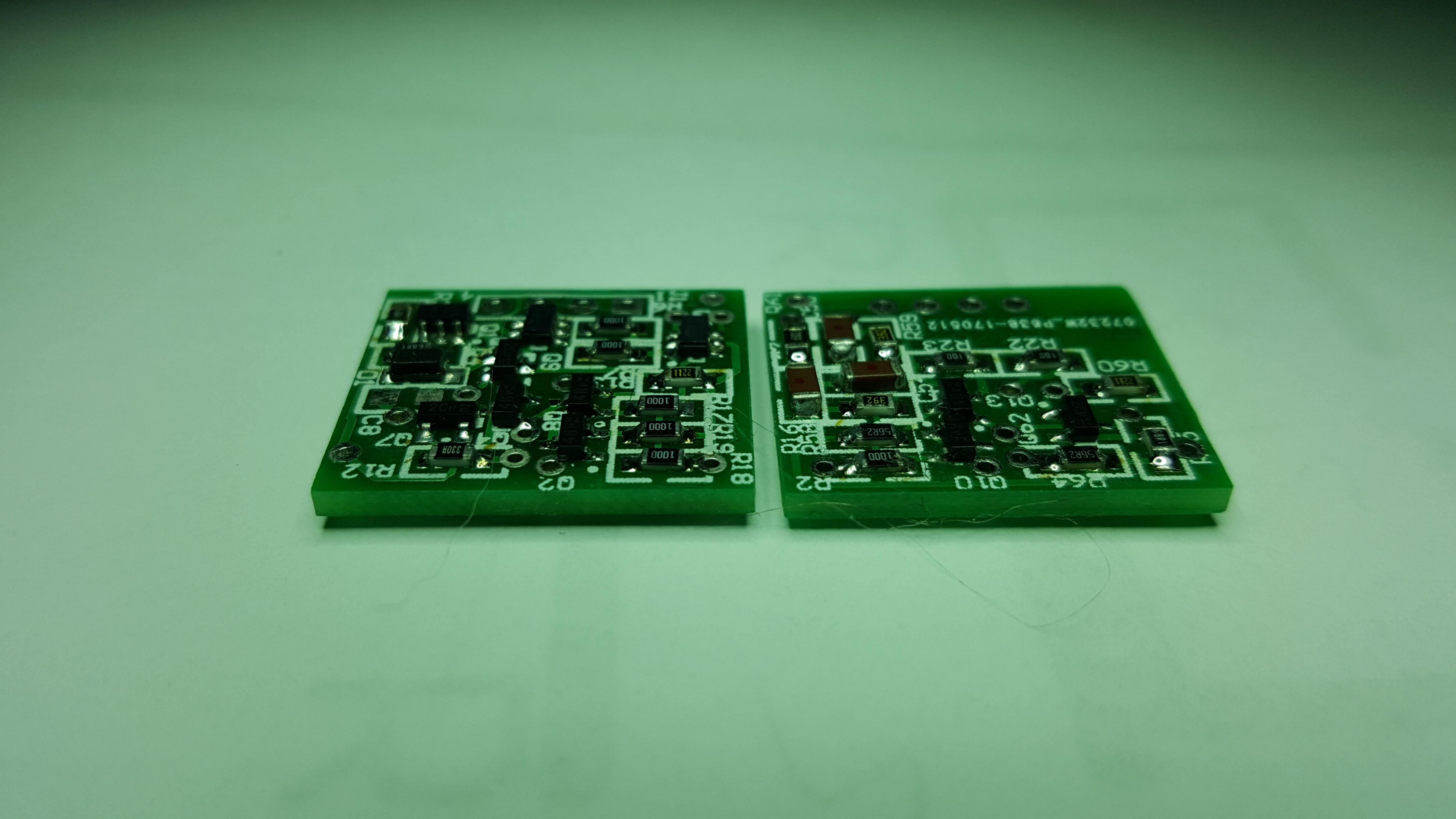
More images to give you some scale of these little buggers:
and thru the microscope which I had to use to solder the bits on:
There are parts on both sides of these PCBs.
A this point I am yet to mount the miller cap, as I want to play with this a bit. On the schematics there is a "guaranteed to work" value. I want to measure the phase margin and stability into some odd loads - as overcooking this will directly affect...
Posted 23rd May 2017 at 09:58 AM byabraxalito Updated 6th July 2017 at 03:28 AM byabraxalito
My Superlux HD668Bs are the best value purchase I've ever made in headphone kit, far and away the best bang for the buck at their very modest price-point. If any pair of cans is worth designing a specific amp for, they are most certainly on the short-list. The amp I designed specifically for my AT MSR-7s doesn't have enough ooomph for these as the impedance is appreciably higher and the efficiency lower.
So here is my attempt at a dedicated HD668B amp with no corners cut in SQ while still being cheaper to buy the parts for than the cans themselves. I've designed it to run from a single lithium ion cell - a Panasonic 18650 would work fine and give around 60hrs of listening time. Its a single-ended classA topology driven by a single current-source loaded MOSFET. And naturally enough it sounds like no amplifier at all - a straight wire without gain, seeing as its just a buffer.
In actual fact it certainly does have gain, but only current gain. And no shortage of...
Posted 17th May 2017 at 10:37 PM bySyncTronX Updated 17th May 2017 at 11:36 PM bySyncTronX(add images)
JFET Amplifier and Filter Project.
Background
A lab was developed with something a little bit more hands on for participants than just blindly doing the NIDA labs. We would benefit from making an N-Channel JFET amplifier and asked if we would be interested. Of course, we werent told the JFET type or gain and didnt know wed also include a bandpass filter. These parameters wed have a drawing from which to choose. Finally, wed have to document and report the entire process in APA format. Process
Each project is unique and provided on two stapled pages placed upside down in a mixed pile at the front of the room. Each participant was asked to come up and draw their project. I drew project labeled E on the upper right corner of the second page. Included were the following: JFET 2N5485 or 2N5458, Gain set to 22, the Bandpass to be 15kHz 30kHz, and Total Circuit DC Power as Calculated/Measured.
Other resources were...
Well here I am travelling again, and this time stuck for an extra week away from home. The design bug has bit, and this time I tried keeping things small rather than crazy.
I have built a number of discrete operational amplifiers in the past. Usually integrating everything onto the board so that they wind up being preamplifiers rather than operational amplifiers.
If that confuses you - the difference is that an operational amplifier needs to be plugged into a circuit to be useful, a preamp is a standalone PCB.
The inspiration was seeing a burson amp on ebay. I looked and thought to myself "I keep starting that, and keep ending up with a preamp". Then I thought "Do it right for once".
The resultant goals:
- Dual channel op amp
- DIP8 pinout
- Good perfromance
- Class A (vs class AB which many are)
- Minimum size, whilst
- Sticking to 0805 SMD resistors caps, and...
As avid readers of my blog over the years may well know, I've modded quite a few active speakers. Mainly Swan/Hivi D1010s and D1080s of various generations along with some 3Nods. The entry level Swans are super-cheap on Taobao nowadays with pairs of older generation D1010s going for about 375rmb.
As a result of all these mods and my learning by doing I haven't got a single pair of actives in working condition, primarily because the mods I currently want to do (including fitting transformers inside and swapping out the classAB chipamps on bass/mid to replace with classD) won't fit in the available space. All the amp and active XO parts have been hacked about almost beyond recognition and are of very dubious reliability. So I have come up with a plan - I've thrown all the electronics boards away and will convert the carcasses into passive speakers. Since I also prefer to feed speakers via step-down transformers for better dynamics, I wanted to explore the possibilities of using...
While I consider this my best work to date, the documentation trail has become hopelessly scattered so let me try to regroup in this blog post and make some sort of gateway/portal to the project. [Update: web page write up now finished.]
The followup to the Sapphire 3 started out as a generic musing on stacked diamond buffers and current mirror amplification, coalesced for a bit as the ill-fated Project Unity before becoming part of the Sapphire line initially as a temporary measure as something I could drop in my existing chassis for testing. The first iteration kept the open loop buffer of previous Sapphire iterations, but now I'm running the 4.1m boards with the buffer inside the feedback loop I realize I've ended up at just the classic, dictionary definition current feedback amplifier (CFA). Sigh. So much for originality. It sounds great though, so I'm not as upset about it as I might have been.
Posted 22nd April 2017 at 04:30 AM bygooglyone Updated 22nd April 2017 at 04:40 AM bygooglyone
After a few months of playing with loudspeaker drivers and software fixes to code that I wished I had never written in the first place, the lure of the BJT loomed large again...
There I was, sitting at my desk, and pondering where these dark feelings were coming from and how to scratch that evil itch, and my eyes came to rest upon that most ludicrous of things - the amplifier of 100 transistors.
About a year ago, or so it seems to me sitting here, I built this homage to the BC549, or as the engineer in me says, "Laughably stupid thing, which probably shouldn't work. Who would be dumb enough to try and find out?".
It needed a case. It needed a power supply. It deserved each of the above that would allow it to work, and ideally take an equally "left field" approach. it should never have been built, but it had. It should have been put in the back of a very dark, locked cupboard, but it had not.