

Discrete Op Amp measurements
Posted 12th June 2017 at 06:25 AM by googlyone
Updated 12th June 2017 at 06:30 AM by googlyone (errors!)
Updated 12th June 2017 at 06:30 AM by googlyone (errors!)
I finally got around to doing some measurements on the discrete op amp at G=2 and G=10.
These were non inverting mode - note the voltage was 6-8V p-p, and the rails were +/-15V so there was a fair whack of headroom. Anyway, I will let the measurements speak for themselves.
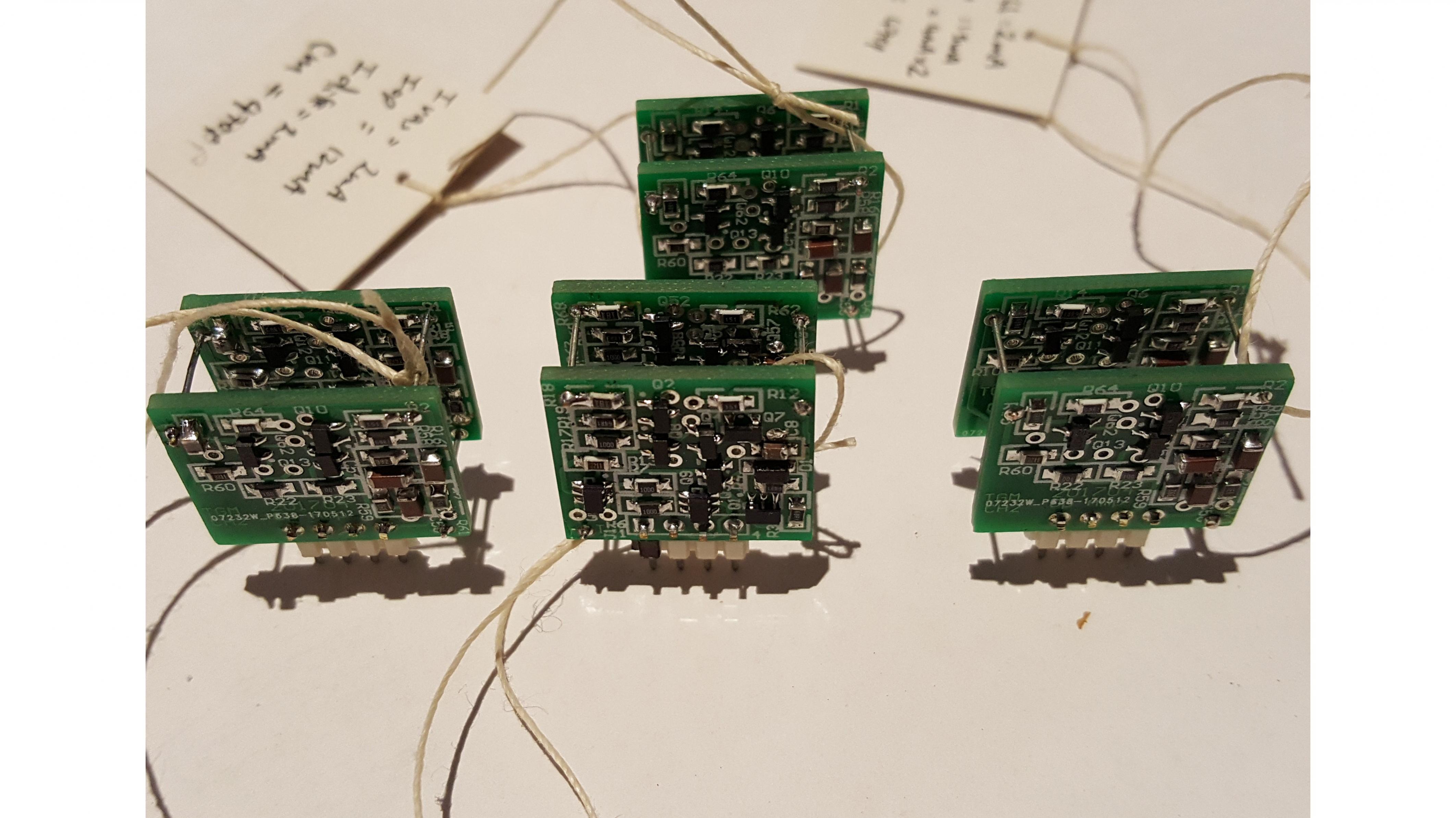
This is what they looked like...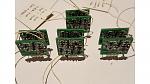
I tested a whole bunch of configurations of the DOA, including:
Differential pair current 1, 1.5, 2 and 4mA
Output current 8mA (2* 4mA) and 12mA
VAS current 1.5, 3mA.
The test setup was a dual op amp board, one channel set to G=2 the second set to G=10.
The load for G=2 was 1kOhm. The load on G=10 was 10kOhm. I could go back and retest this... I had not lingered on this during the test.
The first challenge I found was MASSES of noise really messing with the results. It looked a lot like oscillation, and I kid you not, I spent hours trying to stabilise things until I remembered my microscope light was a very chap Chinese thing, and had given me trouble in the past.
Turning the microscope light off saw the noise floor drop from -80dB to -130-140. This was with the microscope FEET from the test setup!
The second thing I noted was that at higher frequencies the measurement system was messing with things.
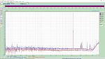
G=10
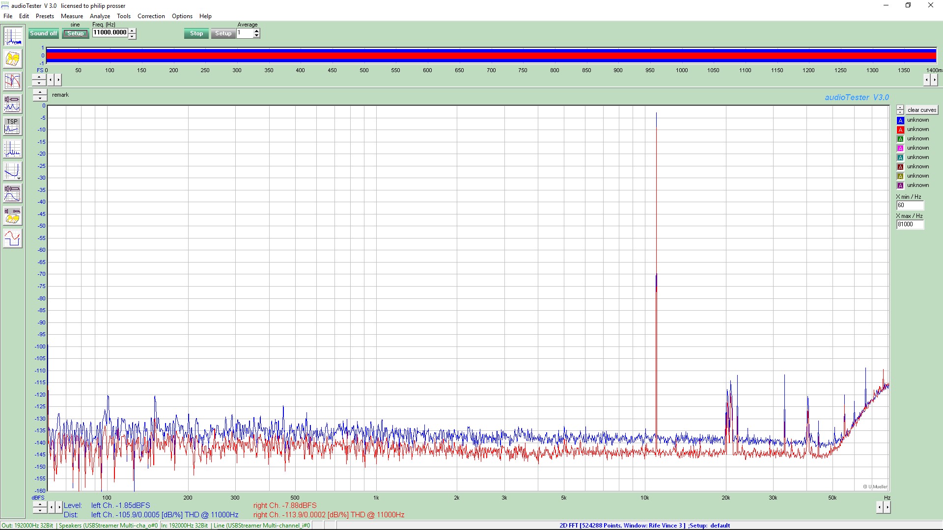
This is an FFT of an 11kHz signal:
G= 2
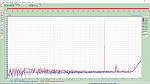
There are a few artefacts of note to be seen here:
- There is some fluff at about 20KHz odd. This is always there.
- There is rising noise above 50kHz.
In some of the test I told the software to discard harmonics above 60kHz. This results in measured distortion above 20kHz being flat-ish. It is not entirely clear to me how much that rising noise floor is affecting the results.
*** Above 10KHz I would regard the measurements as being somewhat affected by the test gear.
A second note: Making measurements like these is fiddly. In the end I made a test jig in which I could plug the op amp, and all tests were made one after another by swapping the op amps in and out. G=2 vs G=10 were made using the first or second channel.
On all plots one channel is the input to the op amp, the other the output. This allows me to watch the distortion going into the op amp and loopback on the test setup.
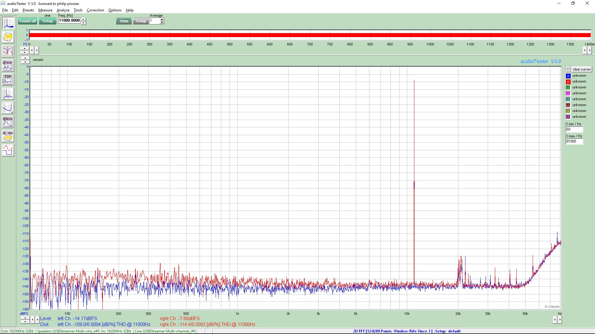
The test results for G=2 really showed that the noise floor on the test gear was the limitation. The test set had the output set to -14dB full scale. This is probably about 8-10dB lower than optimal, and I might have benefited from setting the output to -4-6dB and manually attenuating. But I was too damn lazy, and simply allowing the test set to run have me a level of consistency.
This is the same as the next plot, but with anything above 50MHz excluded from the measurement.
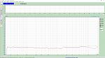
G=2, iDiff pair - 2mA, Ioutput 8mA, Miller cap 470pF
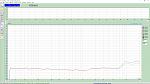
G=2, iDiff pair - 2mA, Ioutput 8mA, Miller cap 470pF - 50kHz cut
G=2, iDiff pair - 2mA, Ioutput 12mA, Miller cap 470pF
My take on this is that for G=2 the distortion is below the noise floor of the test set. This makes me smile, but is I guess not hugely surprising. Anyway, I call this success.
And for G=10 I ran exactly the same tests, in exactly the same test rig. Simply using the G=10 channel.
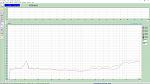
G=10, iDiff pair - 1mA, Ioutput 8mA, Miller cap 470pF, 60kHz LP
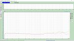
G=10, iDiff pair - 2mA, Ioutput 8mA, Miller cap 470pF
G=10, iDiff pair - 2mA, Ioutput 12mA, Miller cap 470pF
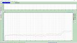
G=10, iDiff pair - 4mA, Ioutput 8mA, Miller cap 470pF
My take on this is that the distortion is well out of the noise floor, especially above 10kHz, but in all cases the distortion is below 0.001% out to 5kHz and stays under 0.005% out to beyond 20kHz.
Again, this counts to me as being very successful. I am happy with the results.
I can see a benefit to increased diff pair current. I also feel better with increased output stage current. I am becoming reconciled to the rather hot Class A output running at 12mA.
I have a version of this using SOT89 output devices, I am very tempted to build some of these.
A less obvious thing that I like about these is the use of the dual op amp pinout. The fact I can simply plug and play with these makes testing a joy.
I am off overseas again next week... I fear I will be coming home from this 5 week trip with yet another design to build and test!
These were non inverting mode - note the voltage was 6-8V p-p, and the rails were +/-15V so there was a fair whack of headroom. Anyway, I will let the measurements speak for themselves.
This is what they looked like...
I tested a whole bunch of configurations of the DOA, including:
Differential pair current 1, 1.5, 2 and 4mA
Output current 8mA (2* 4mA) and 12mA
VAS current 1.5, 3mA.
The test setup was a dual op amp board, one channel set to G=2 the second set to G=10.
The load for G=2 was 1kOhm. The load on G=10 was 10kOhm. I could go back and retest this... I had not lingered on this during the test.
The first challenge I found was MASSES of noise really messing with the results. It looked a lot like oscillation, and I kid you not, I spent hours trying to stabilise things until I remembered my microscope light was a very chap Chinese thing, and had given me trouble in the past.
Turning the microscope light off saw the noise floor drop from -80dB to -130-140. This was with the microscope FEET from the test setup!
The second thing I noted was that at higher frequencies the measurement system was messing with things.
G=10
This is an FFT of an 11kHz signal:
G= 2
There are a few artefacts of note to be seen here:
- There is some fluff at about 20KHz odd. This is always there.
- There is rising noise above 50kHz.
In some of the test I told the software to discard harmonics above 60kHz. This results in measured distortion above 20kHz being flat-ish. It is not entirely clear to me how much that rising noise floor is affecting the results.
*** Above 10KHz I would regard the measurements as being somewhat affected by the test gear.
A second note: Making measurements like these is fiddly. In the end I made a test jig in which I could plug the op amp, and all tests were made one after another by swapping the op amps in and out. G=2 vs G=10 were made using the first or second channel.
On all plots one channel is the input to the op amp, the other the output. This allows me to watch the distortion going into the op amp and loopback on the test setup.
The test results for G=2 really showed that the noise floor on the test gear was the limitation. The test set had the output set to -14dB full scale. This is probably about 8-10dB lower than optimal, and I might have benefited from setting the output to -4-6dB and manually attenuating. But I was too damn lazy, and simply allowing the test set to run have me a level of consistency.
This is the same as the next plot, but with anything above 50MHz excluded from the measurement.
G=2, iDiff pair - 2mA, Ioutput 8mA, Miller cap 470pF
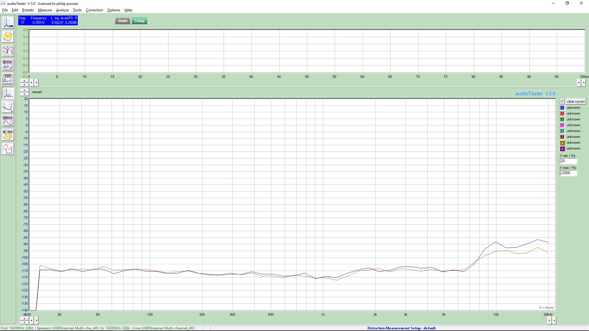
G=2, iDiff pair - 2mA, Ioutput 8mA, Miller cap 470pF - 50kHz cut

G=2, iDiff pair - 2mA, Ioutput 12mA, Miller cap 470pF

My take on this is that for G=2 the distortion is below the noise floor of the test set. This makes me smile, but is I guess not hugely surprising. Anyway, I call this success.
And for G=10 I ran exactly the same tests, in exactly the same test rig. Simply using the G=10 channel.
G=10, iDiff pair - 1mA, Ioutput 8mA, Miller cap 470pF, 60kHz LP
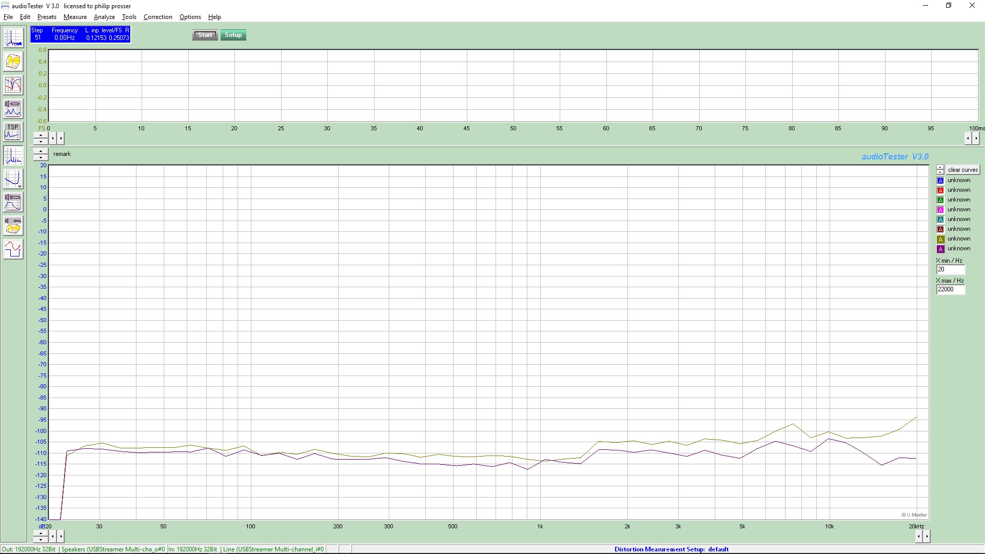
G=10, iDiff pair - 2mA, Ioutput 8mA, Miller cap 470pF
G=10, iDiff pair - 2mA, Ioutput 12mA, Miller cap 470pF
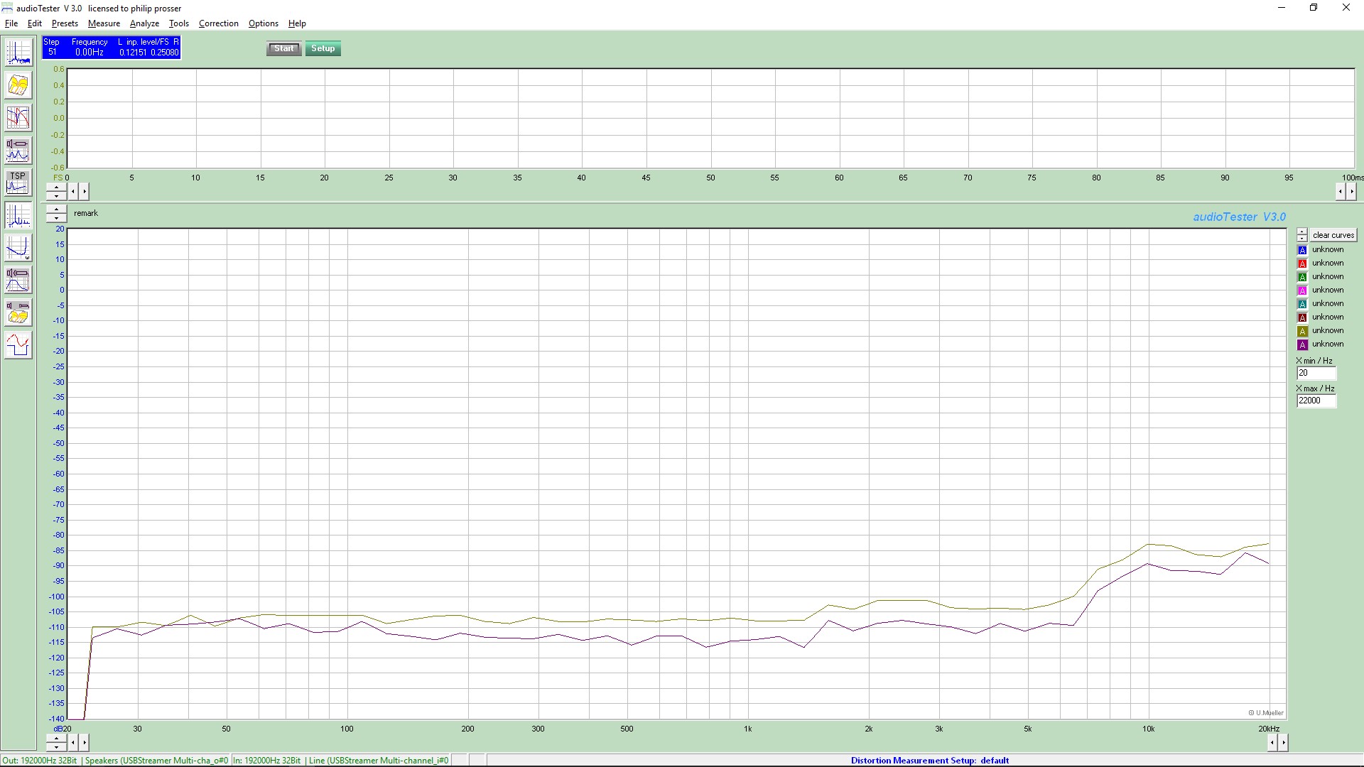
G=10, iDiff pair - 4mA, Ioutput 8mA, Miller cap 470pF

My take on this is that the distortion is well out of the noise floor, especially above 10kHz, but in all cases the distortion is below 0.001% out to 5kHz and stays under 0.005% out to beyond 20kHz.
Again, this counts to me as being very successful. I am happy with the results.
I can see a benefit to increased diff pair current. I also feel better with increased output stage current. I am becoming reconciled to the rather hot Class A output running at 12mA.
I have a version of this using SOT89 output devices, I am very tempted to build some of these.
A less obvious thing that I like about these is the use of the dual op amp pinout. The fact I can simply plug and play with these makes testing a joy.
I am off overseas again next week... I fear I will be coming home from this 5 week trip with yet another design to build and test!
Total Comments 1
Comments
-
 Well done indeed !Posted 13th June 2017 at 02:22 PM by kasey197


