

Discrete Op Amp PCB Build
Posted 25th May 2017 at 10:18 PM by googlyone
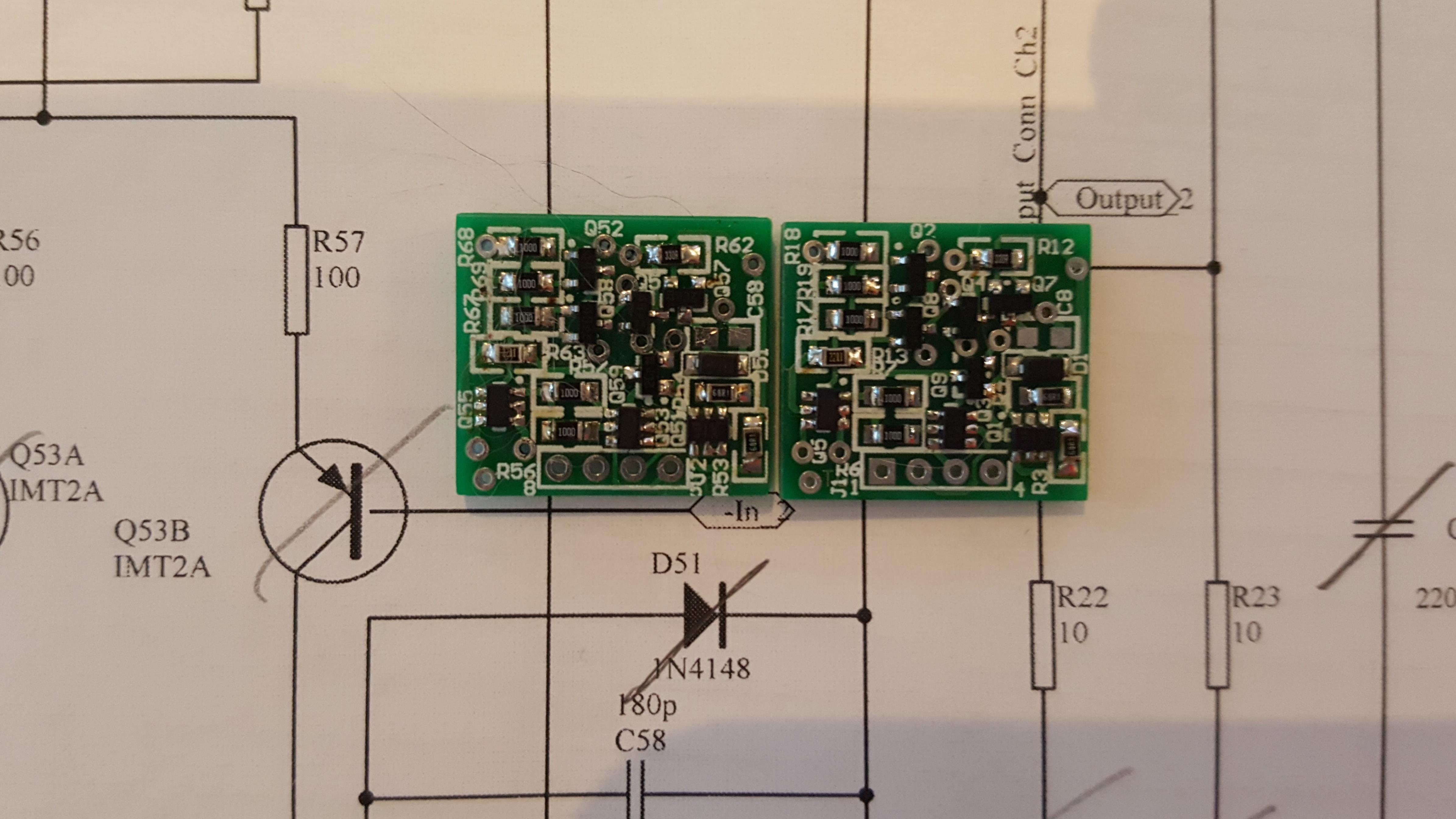
Well I am home again, and the PCBs for the discrete op amp beat me home.
I used PCBcart, who have a very competitive prototype PCB service -it is certainly not worth your time to make fiddly double sided boards like these at home!
They came out like this...
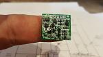
And no, I don't have a finger the size of a baguette...
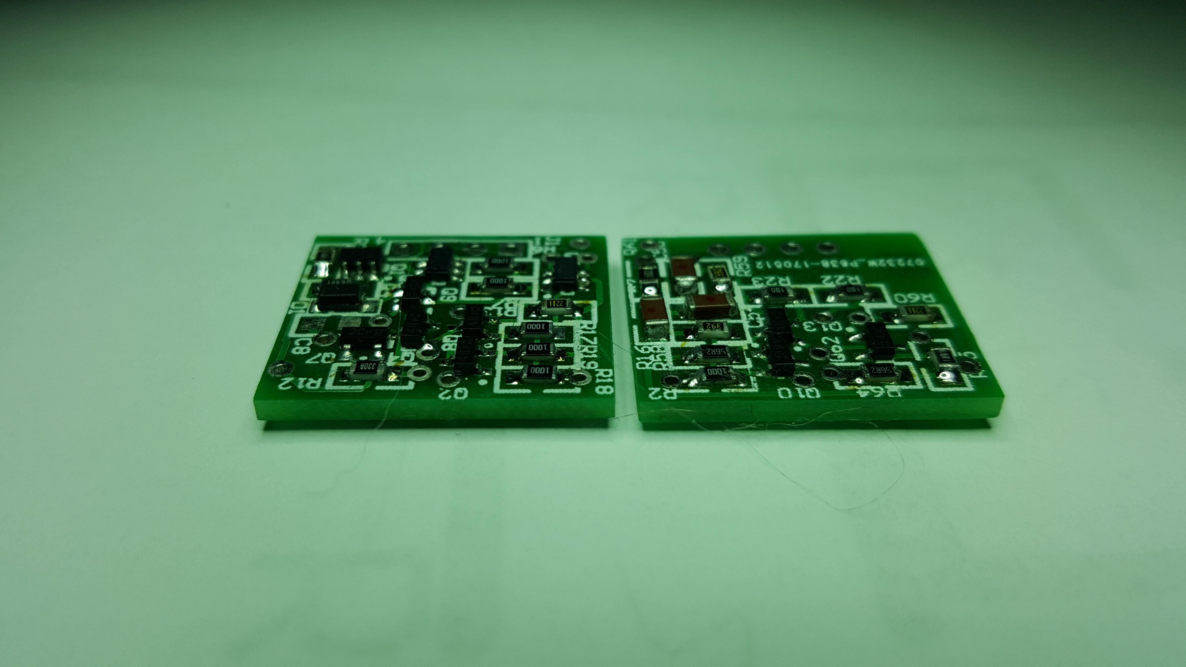
More images to give you some scale of these little buggers:
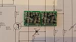
and thru the microscope which I had to use to solder the bits on:
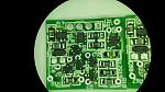
There are parts on both sides of these PCBs.
A this point I am yet to mount the miller cap, as I want to play with this a bit. On the schematics there is a "guaranteed to work" value. I want to measure the phase margin and stability into some odd loads - as overcooking this will directly affect the high frequency feedback.
A couple of notes:
- I usually make my own boards - mainly for the zen like state I enter into while doing it, I find it relaxing.
- For boards like this though they get really fiddly, and where there is a lot of SMD, some patience is required in soldering to bare copper.
- Using the fab for these has made soldering a breeze. I won't be doing 50 pairs, but a dozen is doable.
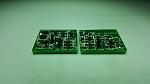
- The whole op amp is the air of boards. Each is essentially one channel and there are three wires between them to provide power back and forth. The four pin header on the edge of each board is essentially pins 1-4 on channel 1 and 5-8 on channel 2.
Next I will drop these into an op amp, and crank up the distortion meter.
All my experience says this will show something in the region of 0.000X% distortion at lower frequencies rising to 0.00Y% (where Y is a rather small number) at high frequencies. for a G-10 op amp.
I will see how that miller feedback affects this.
Hope to do this in the next few days!
I used PCBcart, who have a very competitive prototype PCB service -it is certainly not worth your time to make fiddly double sided boards like these at home!
They came out like this...

And no, I don't have a finger the size of a baguette...
More images to give you some scale of these little buggers:
and thru the microscope which I had to use to solder the bits on:

There are parts on both sides of these PCBs.
A this point I am yet to mount the miller cap, as I want to play with this a bit. On the schematics there is a "guaranteed to work" value. I want to measure the phase margin and stability into some odd loads - as overcooking this will directly affect the high frequency feedback.
A couple of notes:
- I usually make my own boards - mainly for the zen like state I enter into while doing it, I find it relaxing.
- For boards like this though they get really fiddly, and where there is a lot of SMD, some patience is required in soldering to bare copper.
- Using the fab for these has made soldering a breeze. I won't be doing 50 pairs, but a dozen is doable.
- The whole op amp is the air of boards. Each is essentially one channel and there are three wires between them to provide power back and forth. The four pin header on the edge of each board is essentially pins 1-4 on channel 1 and 5-8 on channel 2.
Next I will drop these into an op amp, and crank up the distortion meter.
All my experience says this will show something in the region of 0.000X% distortion at lower frequencies rising to 0.00Y% (where Y is a rather small number) at high frequencies. for a G-10 op amp.
I will see how that miller feedback affects this.
Hope to do this in the next few days!
Total Comments 4
Comments
-
 this is pretty interesting - have you had any time to do the measurements yet ? Say at G=10 and G=2?Posted 7th June 2017 at 12:12 AM by kasey197

-
Only G=2 at present - I have been too busy with work. I hope to get to this.
At G=2:
- I tweaked the diff pair current to 1mA
- I set the slew rate to 8v/us, or miller C = 180pF
- I set the VAS current to 2-3mA (there are a couple of versions)
- I set the output current to 4mA per device or 8mA total.
Most of the above were to manage thermals - with the higher bias currents everywhere on such a tiny board, things got toasty warm. I was not really happy with this given this device is likely to live its life in a confined unventillated space... The curse of CLASS A!
With this:
- the distortion is above the self noise of my distortion test set on loopback.
- The test set, at the output level it is running at, is around -115dB across 20Hz to 20kHz
- The op amp adds a couple of dB to this, or 0.0005%
- this was measured at about +/-5Vpk into 1K Ohms
The high level of NFB makes this measurement hard. I think G=10 will make things a lot clearer.Posted 8th June 2017 at 01:27 PM by googlyone
Updated 8th June 2017 at 01:30 PM by googlyone -
nice going and its looking good
 Posted 9th June 2017 at 08:14 AM by kasey197
-
you're running this in inverting mode i assume ?
non-inverting introduces unnecessary common mode distortion imo..Posted 9th June 2017 at 08:17 AM by kasey197

