

6C33 OTL Fine tuning - BGs, ground and wire dressing
Posted 3rd March 2013 at 03:58 PM by wlowes
Updated 8th December 2014 at 01:39 AM by wlowes (Update - Bulk foil resistors)
Updated 8th December 2014 at 01:39 AM by wlowes (Update - Bulk foil resistors)
The amps continued to run in and proved to be keepers. Well worth doing some final spit and polish. There was a little hum on one amp and some noise / hash on the tweeters of both channels. Nothing major, but certainly audible at 1 foot.
Using AC filament supply for all but the input tube, I figured I should re read the best practices on wire dressing, hum pots, virtual center tap etc.
Looking back there were some spots to improve.
1. tight wire twist on path from bridge rectifier to first caps. Done, no real change.
2. tight twist on b+ supply to input tube plus added BG 3uF 250v cap right at the tube. No change to noise but love the improvement in sound
3. tight wire twist from psu to b+ on all power tubes plus BG 10uF 250v on each power tube. Like the input tube the BG brought an immediate lowering of noise floor that really brought a finishing to the SQ. Quiet background, micro details and just a smooth rich sound. Not colored, just the way it should be.
4. Same on bias supply to power tubes
5. realized long runs of signal wire from coupling caps to power tubes. Just a lot of real estate to cover. Ensured there was good routing of silver plated copper Teflon. Then added a shield using spiral of 22 gauge solid copper grounded at one end.
As all this settled in, SQ continued to refine. But still a little hum on one side. Running down process of elimination swapped power cords. Unbelievable ... Hum moved to other channel!
When I wired up this cord, I was missing an IEC plug. As a temporary solution, I used the end of a commercial PC cord. Either the ground wire was just too small, or there was a poor solder joint. Replacing the plug solved issue. There must have been just enough resistance that the current was flowing back through the interconnect causing a ground loop. Makes sense. Why go to all the trouble of having big thick copper ground wires inside the amp and then a cheap little cable in the path back to ground. I plan to add a heavier ground wire through the cords as a final touch.
At this stage, both channels have zero hum. One is so quiet I am hard pressed to tell if it is powered with ear tight to tweeter. The other still has a slight high pitch noise at the tweeter.
Not worth chasing.
[edit March 10] Interesting.. I had a look at the amp making some high pitched noise on the tweeter. Nothing looked amiss with wiring, and then I noticed that the filament wiring on one side of one tube had not been soldered! Clearly it was making contact or the tube would not be heated. Soldered this and now get more apparent detail in the sound stage.
Next, since I realized that I had had insufficient gauge wire on the power cord, I beefed up both power cords by adding a second run of 18gauge safety ground. To carry this on through I added a run of 12 gauge copper through the path of the power conditioner. The power cord to the power conditioner already has heavy gauge. This had two outcomes. First the good news is SQ jumped ahead with far more micro detail. One of those got to go listen to everything moments yet again. On the bad side unearthed the potential for all kinds of ground path issues across the system. I am starting to learn it is not just good enough to worry about ground path within the amp. All components need to had enough ground capacity to drain away without forcing some level of signal contamination across the single ended RCA cable. Still some minor things to chase but I am learning and the sound continues to improve.
The Black Gates have about 30+ hours on them. The notoriously slow break in is well along. They will continue to improve over the next 100 hours, but more like fine wine in the cellar. Quite ready to enjoy. The congestion and lack of air that comes with new caps is evaporating and leaving a lot of easy listening detail and space.
The author of the circuit design insists there is no value in part quality. I cannot agree. I can't speak to the value of using premium resistors as I jumped in with high quality. The addition of the BG caps was nothing short of surprising. At $6 each, an amazing value. Every day the sound improves.
[Power Conditioner Update]
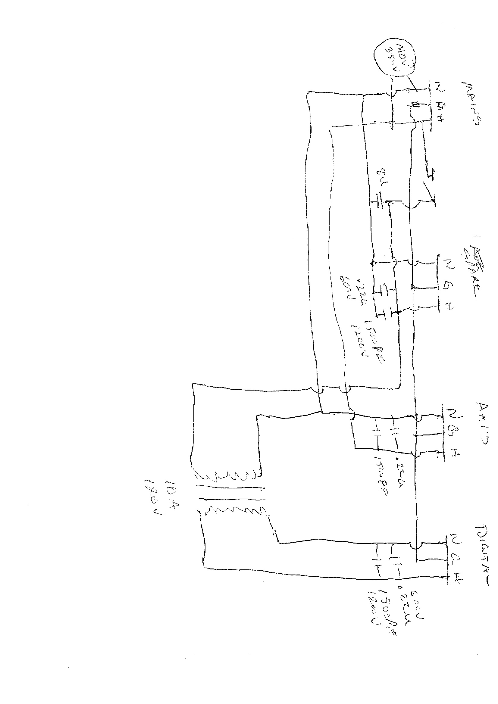
I continued to focus on getting clean power to the amps. I upgraded the IEC plugs on all the power cords. This gave a nice little bump up in sound quality. Next step was to increase the gauge of the solid copper wire within the power distribution/conditioner. I had always had some 4uF poly caps on the line and neutral lines back to ground. As an experiment, I added a 6uF 1200v motor run cap (pulled from a microwave oven) across the line to neutral. This clearly increased the sound quality. After some web research I added Russian 600v .1uf teflon tin foil caps right across the line/neutral on each of the outlets on the power conditioner. This produced all the impact often reported. Then added Russian silver mica 1200V 1500pf caps to bypass the Teflon. These adds really allow the amps to realize their full potential. As often reported a deep black background in which individual instruments sit naturally in appropriate space. Much deeper and tighter bass. Right across the spectrum the compelling adjective is natural. Less noise floor; more micro detail; natural easy to listen presentation. Some things like horns particularly shift to natural.
As good as the amps are, running them without good power cords and a good power conditioner means leaving a lot of their potential behind.
Just to summarize.. the conditioner uses roughly 14 gauge solid copper wire to the amps with 6uf motor run filter/.1 tin Teflon/1500pf silver mica.
The DAC gets the benefit of the motor run cap then a 1kVA isolation transformer/.1 tin foil Teflon bypassed with 1500pf silver mica.
The entire conditioner has an MOV designed to clamp any spike above 350V. The conditioner is in a good sized steel chassis (an old power amp) with lots of vents. An MOV or a capacitor can and will destruct catastrophically if it receives sufficient over voltage. I believe in the unlikely event this conditioner were to suffer a destructive spike there would be sufficient venting and space to dissipate the blast without damaging the premise. (unlike most power bars which can burn down your home). I do not advocate that anyone follow this route and bear no liability for anyone attempting to duplicate this configuration. I provide this information only to document my personal experience in this journey. [end update] [ATTACH]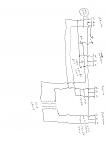 [/ATTACH]
[Update May 13] Couple more small but significant tweaks.
1. Added some vibration dampening to the power conditioner. Just some sand bags laid over wires and components. Well worth it.
2. Speaker wires had been bi-wired (hold over from long time ago) Wire to main drivers longer than cable to tweeters. Eliminated bi wiring but kept same volume of wire and ensured all the cables same length. This tightened up the sound stage and eliminated some smearing. I think bi-wiring in some cases gives the impression of bigger image but its a trick. If the gear is finely resolved its better without the echo chamber induced with bi-wiring. Also, I believe it takes 14 nano seconds to travel 1 foot. Uneven wire length may contribute to timing issues.
3. The big surprise... Swapped out 18 AWE power cords & replaced with 12AWE. I am convinced that dynamics became snappier but sound if anything more relaxed. More musical. Is this what they mean when they say faster? How could this be? Amp designer claims power cord makes no difference to sound. He says only his design counts. Not so in my case. BG and Teflon caps, power conditioning and again power cords all make big impact. I read somewhere that the designer tends to build his kits a bit underspec'd in the power supply. I imagine that if the transformer is the weak link, then improved power cord makes no difference. I built with 500VA toroids on each of the push and pull circuits with separate bridge rectifiers. At least 4X what is called for by the designer. In this case increasing current delivery capability to the transformer may account for the noticeably faster transients. Regardless of the explanation it sounds great. I think over specifying the power supply was well worth the effort (and weight).
[end update]
[update Sept 13 - feedback resistors]
Next tweak came as a result of resistor experiments on my DAC. I replaced one of the feedback resistors with a Caddock TF020 resistor. It replaced an Alan Bradly 3k in that position. There are actually 2 AB resistors in parallel. One can be switched into the circuit to allow more feedback. I find I almost always run with lower feedback so I thought I'd try replacing one only. It kind of surprised me that there was an immediate and important improvement. Another jump in resolution. A little tighter bass. Even more clarity around individual sounds placed in 3d space. Now the best part is there is a fair bit of improvement over time as the resistors settle in. After now 100 hrs, it is quite good. The resistor changed is R9. To complete the chain, I will one day put the same resistors in R10, the other feedback resistor, R2, and R3. Anyone building this amp or ones like it would be well advised to put these $6 wonders in place from day one. The OTL format is ready to let every nuance of sound through so these little increases in clarity are really well worth the effort.
[end update]
[Sept 22 2013 silver update]
Finally replenished my supply of 24 gauge silver wire. Removed existing silver plated copper teflon where ever accessible and replaced with 99.9 silver. There are a couple of connections between small tubes that are not accessible. Also left the signal wire from V3 to the coupling cap. All cap to power tube paths replaced. There also is a path from power tubes to speaker post that has 14 gauge naked copper. I left the heavy copper and added a parallel run of silver. In this amp there is no doubt the change is made. To my taste a substantial improvement and would be the recommended approach from the beginning. Some might prefer the copper. With the change you realize that the copper mushes the higher registers a bit, and rolls off the higher registers. It is not a problem. The distortion imparted by the copper is pleasant and a bit tube like. The silver sound just shines. A lot clearer in the upper registers and very crystal clear. Cymbals shimmer for ever. Sounds are even more tightly focused in space. I already used silver in the interconnects and speaker cables. Now only the signal wire in the DAC is copper.
My source for silver is Myron Toback in NYC. Works out to be about a buck a foot. Minimum order is 1 oz. Cost $50 delivered to Toronto.
[end update]
[Sept 21 2014 Vishay Bulk Foil]
I notice its been a full year since I have touched the amps with a hot iron. This recent update is to note I exchanged a couple of more resistors. Partsconnextion had a sale on Vishay Bulk Foil. R1 100k is coupled between the grid of V1 and ground which sets the input impedance. They were out of 100k, so I used a 98.5R. No problem. I also added a run of 24 guage silver between the RCA positive and the grid. There was just a 28 guage silver in place previously. The distance is only about an inch. Ran the resistor parallel to the signal wire to ground to minimize loop area.
Then came series coupled resistors R2 (3k) and R3 (100) which are coupled between the cathode of V1 and ground creating a negative bias voltage of 1.5v. I had great results earlier by replacing the 3k feedback resistor R9. Again, not all the exact parts were available. I had used a 3.3k vishay in R9, and again used 3.3k in R2. This sets a little lower feedback which is fine by me.
Another astonishing jump in resolution and overall quiet. Noise floor drops. At first the sound is tight. These need to break in and open up. I am replacing pretty good resistors and yet the improvement is well worth the crazy price for these little gems.
[end update]
I used to say the amps are done. Looks like there is always something left to improve. Only time will tell.
I look forward to speaker design to allow their full potential to be realized.
Using AC filament supply for all but the input tube, I figured I should re read the best practices on wire dressing, hum pots, virtual center tap etc.
Looking back there were some spots to improve.
1. tight wire twist on path from bridge rectifier to first caps. Done, no real change.
2. tight twist on b+ supply to input tube plus added BG 3uF 250v cap right at the tube. No change to noise but love the improvement in sound
3. tight wire twist from psu to b+ on all power tubes plus BG 10uF 250v on each power tube. Like the input tube the BG brought an immediate lowering of noise floor that really brought a finishing to the SQ. Quiet background, micro details and just a smooth rich sound. Not colored, just the way it should be.
4. Same on bias supply to power tubes
5. realized long runs of signal wire from coupling caps to power tubes. Just a lot of real estate to cover. Ensured there was good routing of silver plated copper Teflon. Then added a shield using spiral of 22 gauge solid copper grounded at one end.
As all this settled in, SQ continued to refine. But still a little hum on one side. Running down process of elimination swapped power cords. Unbelievable ... Hum moved to other channel!
When I wired up this cord, I was missing an IEC plug. As a temporary solution, I used the end of a commercial PC cord. Either the ground wire was just too small, or there was a poor solder joint. Replacing the plug solved issue. There must have been just enough resistance that the current was flowing back through the interconnect causing a ground loop. Makes sense. Why go to all the trouble of having big thick copper ground wires inside the amp and then a cheap little cable in the path back to ground. I plan to add a heavier ground wire through the cords as a final touch.
At this stage, both channels have zero hum. One is so quiet I am hard pressed to tell if it is powered with ear tight to tweeter. The other still has a slight high pitch noise at the tweeter.
Not worth chasing.
[edit March 10] Interesting.. I had a look at the amp making some high pitched noise on the tweeter. Nothing looked amiss with wiring, and then I noticed that the filament wiring on one side of one tube had not been soldered! Clearly it was making contact or the tube would not be heated. Soldered this and now get more apparent detail in the sound stage.
Next, since I realized that I had had insufficient gauge wire on the power cord, I beefed up both power cords by adding a second run of 18gauge safety ground. To carry this on through I added a run of 12 gauge copper through the path of the power conditioner. The power cord to the power conditioner already has heavy gauge. This had two outcomes. First the good news is SQ jumped ahead with far more micro detail. One of those got to go listen to everything moments yet again. On the bad side unearthed the potential for all kinds of ground path issues across the system. I am starting to learn it is not just good enough to worry about ground path within the amp. All components need to had enough ground capacity to drain away without forcing some level of signal contamination across the single ended RCA cable. Still some minor things to chase but I am learning and the sound continues to improve.
The Black Gates have about 30+ hours on them. The notoriously slow break in is well along. They will continue to improve over the next 100 hours, but more like fine wine in the cellar. Quite ready to enjoy. The congestion and lack of air that comes with new caps is evaporating and leaving a lot of easy listening detail and space.
The author of the circuit design insists there is no value in part quality. I cannot agree. I can't speak to the value of using premium resistors as I jumped in with high quality. The addition of the BG caps was nothing short of surprising. At $6 each, an amazing value. Every day the sound improves.
[Power Conditioner Update]
I continued to focus on getting clean power to the amps. I upgraded the IEC plugs on all the power cords. This gave a nice little bump up in sound quality. Next step was to increase the gauge of the solid copper wire within the power distribution/conditioner. I had always had some 4uF poly caps on the line and neutral lines back to ground. As an experiment, I added a 6uF 1200v motor run cap (pulled from a microwave oven) across the line to neutral. This clearly increased the sound quality. After some web research I added Russian 600v .1uf teflon tin foil caps right across the line/neutral on each of the outlets on the power conditioner. This produced all the impact often reported. Then added Russian silver mica 1200V 1500pf caps to bypass the Teflon. These adds really allow the amps to realize their full potential. As often reported a deep black background in which individual instruments sit naturally in appropriate space. Much deeper and tighter bass. Right across the spectrum the compelling adjective is natural. Less noise floor; more micro detail; natural easy to listen presentation. Some things like horns particularly shift to natural.
As good as the amps are, running them without good power cords and a good power conditioner means leaving a lot of their potential behind.
Just to summarize.. the conditioner uses roughly 14 gauge solid copper wire to the amps with 6uf motor run filter/.1 tin Teflon/1500pf silver mica.
The DAC gets the benefit of the motor run cap then a 1kVA isolation transformer/.1 tin foil Teflon bypassed with 1500pf silver mica.
The entire conditioner has an MOV designed to clamp any spike above 350V. The conditioner is in a good sized steel chassis (an old power amp) with lots of vents. An MOV or a capacitor can and will destruct catastrophically if it receives sufficient over voltage. I believe in the unlikely event this conditioner were to suffer a destructive spike there would be sufficient venting and space to dissipate the blast without damaging the premise. (unlike most power bars which can burn down your home). I do not advocate that anyone follow this route and bear no liability for anyone attempting to duplicate this configuration. I provide this information only to document my personal experience in this journey. [end update] [ATTACH]
 [/ATTACH]
[Update May 13] Couple more small but significant tweaks.
1. Added some vibration dampening to the power conditioner. Just some sand bags laid over wires and components. Well worth it.
2. Speaker wires had been bi-wired (hold over from long time ago) Wire to main drivers longer than cable to tweeters. Eliminated bi wiring but kept same volume of wire and ensured all the cables same length. This tightened up the sound stage and eliminated some smearing. I think bi-wiring in some cases gives the impression of bigger image but its a trick. If the gear is finely resolved its better without the echo chamber induced with bi-wiring. Also, I believe it takes 14 nano seconds to travel 1 foot. Uneven wire length may contribute to timing issues.
3. The big surprise... Swapped out 18 AWE power cords & replaced with 12AWE. I am convinced that dynamics became snappier but sound if anything more relaxed. More musical. Is this what they mean when they say faster? How could this be? Amp designer claims power cord makes no difference to sound. He says only his design counts. Not so in my case. BG and Teflon caps, power conditioning and again power cords all make big impact. I read somewhere that the designer tends to build his kits a bit underspec'd in the power supply. I imagine that if the transformer is the weak link, then improved power cord makes no difference. I built with 500VA toroids on each of the push and pull circuits with separate bridge rectifiers. At least 4X what is called for by the designer. In this case increasing current delivery capability to the transformer may account for the noticeably faster transients. Regardless of the explanation it sounds great. I think over specifying the power supply was well worth the effort (and weight).
[end update]
[update Sept 13 - feedback resistors]
Next tweak came as a result of resistor experiments on my DAC. I replaced one of the feedback resistors with a Caddock TF020 resistor. It replaced an Alan Bradly 3k in that position. There are actually 2 AB resistors in parallel. One can be switched into the circuit to allow more feedback. I find I almost always run with lower feedback so I thought I'd try replacing one only. It kind of surprised me that there was an immediate and important improvement. Another jump in resolution. A little tighter bass. Even more clarity around individual sounds placed in 3d space. Now the best part is there is a fair bit of improvement over time as the resistors settle in. After now 100 hrs, it is quite good. The resistor changed is R9. To complete the chain, I will one day put the same resistors in R10, the other feedback resistor, R2, and R3. Anyone building this amp or ones like it would be well advised to put these $6 wonders in place from day one. The OTL format is ready to let every nuance of sound through so these little increases in clarity are really well worth the effort.
[end update]
[Sept 22 2013 silver update]
Finally replenished my supply of 24 gauge silver wire. Removed existing silver plated copper teflon where ever accessible and replaced with 99.9 silver. There are a couple of connections between small tubes that are not accessible. Also left the signal wire from V3 to the coupling cap. All cap to power tube paths replaced. There also is a path from power tubes to speaker post that has 14 gauge naked copper. I left the heavy copper and added a parallel run of silver. In this amp there is no doubt the change is made. To my taste a substantial improvement and would be the recommended approach from the beginning. Some might prefer the copper. With the change you realize that the copper mushes the higher registers a bit, and rolls off the higher registers. It is not a problem. The distortion imparted by the copper is pleasant and a bit tube like. The silver sound just shines. A lot clearer in the upper registers and very crystal clear. Cymbals shimmer for ever. Sounds are even more tightly focused in space. I already used silver in the interconnects and speaker cables. Now only the signal wire in the DAC is copper.
My source for silver is Myron Toback in NYC. Works out to be about a buck a foot. Minimum order is 1 oz. Cost $50 delivered to Toronto.
[end update]
[Sept 21 2014 Vishay Bulk Foil]
I notice its been a full year since I have touched the amps with a hot iron. This recent update is to note I exchanged a couple of more resistors. Partsconnextion had a sale on Vishay Bulk Foil. R1 100k is coupled between the grid of V1 and ground which sets the input impedance. They were out of 100k, so I used a 98.5R. No problem. I also added a run of 24 guage silver between the RCA positive and the grid. There was just a 28 guage silver in place previously. The distance is only about an inch. Ran the resistor parallel to the signal wire to ground to minimize loop area.
Then came series coupled resistors R2 (3k) and R3 (100) which are coupled between the cathode of V1 and ground creating a negative bias voltage of 1.5v. I had great results earlier by replacing the 3k feedback resistor R9. Again, not all the exact parts were available. I had used a 3.3k vishay in R9, and again used 3.3k in R2. This sets a little lower feedback which is fine by me.
Another astonishing jump in resolution and overall quiet. Noise floor drops. At first the sound is tight. These need to break in and open up. I am replacing pretty good resistors and yet the improvement is well worth the crazy price for these little gems.
[end update]
I used to say the amps are done. Looks like there is always something left to improve. Only time will tell.
I look forward to speaker design to allow their full potential to be realized.
Total Comments 0


