We've had this discussion before. I was trying to get my SPICE model to show some of the quirks you found in real life but haven't done any serious work since 2014.I think this is more a problem of the too less distance between the OPS devices. The gate stopper resistors are less as 5 mm in distance to the OPS devices plastic body - but how to get shorter?
.....
BTW: haven't we found out during development of the high performance SA2014 amplifier that the distance from IPS/VAS to OPS doesn't play such a big role (speed of light) if correctly compensated. My 8 pairs SA2014 has a distance from OPS to VAS of minimum 250mm and maximum of 600mm due to the many devices!
Also, I haven't done any 'real life' stuff on big amps for nearly 2 decades so I have to just make notes of your 'real life' experience for further study including ....
Maybe the answer is to keep Iq below 100mA/device 😀The subtle higher distortions start when the bias will be increased to above 100mA per device and hence the interaction between the OPS devices will increase too.
For oscillation at 20MHz you want an RC with a corner frequency of say 7MHz, low enough that the R isn't obstructed by the C at the problem frequency.
It may help to inspect the current loops connecting each MOSFET pin to another.
Figure 5 shows some basic oscillator configurations. Although seeing you amp in context of all possible variants of these oscillators is not an easy task.
CordellAudio.com - A MOSFET Power Amplifier with Error Correction
Thx!
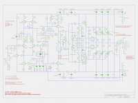
All part names referenced to schematic from post #1700
All exicons Rgate N/P: 180R/120R, CgateDrain 10pF
All caps used for testing (maybe not the best but on stock) MLCC NP0/C0G caps 5% tolerance (e.g. Kemet C317C220J2G5TA 200V/22pF)
C7 + 47R + about 2000 nH is our R+L+C candidate.
The pcb wires (length/loop diameter) can not explain this relative large L and the measured frequencies do not match the calculated ones.
Maybe I was to agressive with the extra compensation caps?
Simulation doesn't show any signs of instability here compared to the real world. 🙁
BR, Toni
P.S.: have to buy a new spectrum analyzer. My ears are swollen from the very loud HP 3585A spectrum analyzer.
All part names referenced to schematic from post #1700
All exicons Rgate N/P: 180R/120R, CgateDrain 10pF
- C7 10p - no subtle oscillation
- C7 15p - no subtle oscillation
- C7 18p - frequency is around 23.4 Mhz
- C7 22p - frequency is around 23.1 Mhz
- C7 27p - frequency is around 21.2 Mhz
- C7 33p - frequency is around 19.8 Mhz
- C7 40p - frequency is around 18.4 Mhz
All caps used for testing (maybe not the best but on stock) MLCC NP0/C0G caps 5% tolerance (e.g. Kemet C317C220J2G5TA 200V/22pF)
C7 + 47R + about 2000 nH is our R+L+C candidate.
The pcb wires (length/loop diameter) can not explain this relative large L and the measured frequencies do not match the calculated ones.
Maybe I was to agressive with the extra compensation caps?
Simulation doesn't show any signs of instability here compared to the real world. 🙁
BR, Toni
P.S.: have to buy a new spectrum analyzer. My ears are swollen from the very loud HP 3585A spectrum analyzer.
Attachments

Last edited:
Toni,i'm sure you can find the solution to the problem.🙂
Spectrume analaizer....
Never i had access to such a thing.🙁🙁
Spectrume analaizer....
Never i had access to such a thing.🙁🙁
Toni,i'm sure you can find the solution to the problem.🙂
Spectrume analaizer....
Never i had access to such a thing.🙁🙁
Hopefully I find the solution!
BTW: for DIY audio you can use a good soundcard and ARTA too. I often use ARTA for IMD tests.
Personally I think it's time Toni purchased an APx555 😉
😉 ... too expensive for a hobby. Currently the VP-7723D is good enough for my needs. To replace or in addition to my very loud HP3585A (makes as much noise as a starting helicopter) I have this part on my focus: Siglent SSA3021X
BR, Toni
Last edited:
Hi Toni,
Apart from sharing your passion for good gear. One can never have enough 😀 Couldn't you just replace the fan or what ever that makes the noise?
Cheers,
Mogens
Apart from sharing your passion for good gear. One can never have enough 😀 Couldn't you just replace the fan or what ever that makes the noise?
Cheers,
Mogens
When you get resonances where too much inductance is implicated, it tends to have to do with the feedback loop of the amplifier rather than the inductance of the wiring. The amplifier can create a virtual 2uH inductance for instance, and than the MOSFET can cause the oscillation between that and it's capacitance.
Another possibility is that it's not Cgd that's oscillating, but Cgs which is much larger. I don't know how that would happen though.
You could check that you output L/R network still has a working R.
Also if you have an output cable connected it's LC could be interacting with the oscillation.
Another possibility is that it's not Cgd that's oscillating, but Cgs which is much larger. I don't know how that would happen though.
You could check that you output L/R network still has a working R.
Also if you have an output cable connected it's LC could be interacting with the oscillation.
Also, your scope probes create a ground loop which is inductive enough to resonate. Try moving the ground clips to the heatsink or somewhere else.
SA2016: using lateral mosfets EXC10N20 EXC10P20
Next step: using C7 10pF, remove all 6 CgateDrain and check again for oscillations.
BR, Toni
Many thanks! Think you are right here! The oscillation frequency can be changed with different C7 values and the relatively high L must be some sort of electronic/virtual inductance. The calculated R+L+C values shows some difference of the frequency. Lower values of C7 stopped oscillations.When you get resonances where too much inductance is implicated, it tends to have to do with the feedback loop of the amplifier rather than the inductance of the wiring. The amplifier can create a virtual 2uH inductance for instance, and than the MOSFET can cause the oscillation between that and it's capacitance.
Next step: using C7 10pF, remove all 6 CgateDrain and check again for oscillations.
Have seen some circuits using lateral mosfets (e.g. 2SK1058) which have external caps from gate to source to compensate the Ciss difference to equalize the gate resistors. (Is this a good idea to do so?)Another possibility is that it's not Cgd that's oscillating, but Cgs which is much larger. I don't know how that would happen though.
OK so far.You could check that you output L/R network still has a working R.
Tested - oscillation is independent of connected resistive 8R load.Also if you have an output cable connected it's LC could be interacting with the oscillation.
Tested - no influence on oscillations. Scope and spectrum analyzer probes are located at output zobel pi network left side.Also, your scope probes create a ground loop which is inductive enough to resonate. Try moving the ground clips to the heatsink or somewhere else.
BR, Toni
Last edited:
...
Next step: using C7 10pF, remove all 6 CgateDrain and check again for oscillations.
...
Works!
- Removed C7
- Removed R26
- Removed all 6 CgateDrain
- C10=27pF, C12=270pF, R31=470R
- Rgate N/P: 180R/120R (very low so far, mostly in use in other projects is 330R/220R and 470R) maybe I will increase the resistor values for more safety margin.
Using small signal square wave: signs of instability starts slightly with C10=15pF, better viewable with C10=10pF.
Back to simulation to check safety margins...
Unnecessary to say, that THD+N is also very good.
What makes this amp very interesting is the fact that bias can be very low and the crossover distortions are still very low!
BR, Toni
Often local MOSFET oscillation is made possible or even caused by the feedback loop.
GS capacitors to equalize capacitance will not make or break an amp, although I suppose they could be used for voicing if the amp's sound is very dependent on the MOSFET behavior. I think I have seen a 100pF GS cap used for stability before with Renesas outputs (equivalent to the single die Exicons).
While you can affect the oscillation with components local to the MOSFETs, you can also affect it by changing the stability compensation. I see no phase lead compensation in the last schematic, so why not try a very small capacitor, say 2.2pF and work up?
EDIT: Oh, I see you solved the problem. Good!
SA2016: using lateral mosfets EXC10N20 EXC10P20
Next step: add current limiter.
Simulation plot file generator used this definition file to generate the plot file (details will follow in the new ltspice/soa thread):
Next step: add current limiter.
Simulation plot file generator used this definition file to generate the plot file (details will follow in the new ltspice/soa thread):
Code:
#
# PGMR: (c) 2016, astx (at) aws-it.at
#
our $traces     =       [
        {
                'soa_of'                =>      'EXC10P20'              ,
                'current_sensor'        =>      'Is(M2)'                ,
                'diff_voltage'          =>      'V(Vnem,-V)'            ,
                'desc'                  =>      'OPS'                   ,
        },
        {
                'soa_of'                =>      'EXC10N20'              ,
                'current_sensor'        =>      'Is(M1)'                ,
                'diff_voltage'          =>      'V(+V,Vem)'             ,
                'desc'                  =>      'OPS'                   ,
        },
];
Attachments

The current limiter must pass all valid audio signals into all valid audio loads.
That requires the limiter to pass transient currents into highly reactive loadings.
This limiter should also protect the output stage from longer term and even DC currents.
Is there a way to differentiate between DC and long term AC and transient AC currents?
So that these different requirements can be analysed?
Can you show the changes to allow the plots to become LogLog to make the SOA "appear" as the manufacturer shows them?
The current limiter must pass all valid audio signals into all valid audio loads.
That requires the limiter to pass transient currents into highly reactive loadings.
This limiter should also protect the output stage from longer term and even DC currents.
Is there a way to differentiate between DC and long term AC and transient AC currents?
So that these different requirements can be analysed?
Can you show the changes to allow the plots to become LogLog to make the SOA "appear" as the manufacturer shows them?
With a one transistor arrangement it will be difficult or impossible to fulfill all your requirements ...
With this kind of VI limiter - if correctly implemented which is not an easy job - your output stage will be protected very good.
If you want minimized influence on sound better omit the VI limiter.
With my perl tool you can generate plots linear and/or LogLog. It depends on how much SOA data lines/points you have extracted from datasheet. In my example you see a longer line which is useful for LogLog display only. Smaller lines (V,A from and V,A to) are then useful if you want to display linear. This picture, the tool and hopefully more discussion about SOA simulation and how to do this can be found here:
http://www.diyaudio.com/forums/solid-state/294790-using-ltspice-check-soa-violations.html
BR, Toni
SA2016: using lateral mosfets EXC10N20 EXC10P20
... have a small amount of test pcb's with 3 mask errors for free
(shipping only EU countries; shipping costs!).
Can be made useable using a cutting tool, knife or something else ...
Send an email to
BR, Toni
... have a small amount of test pcb's with 3 mask errors for free
(shipping only EU countries; shipping costs!).
Can be made useable using a cutting tool, knife or something else ...
Send an email to
sa2016 (at) aws-it.at
if you like to participate on the beta test ...
BR, Toni
Attachments
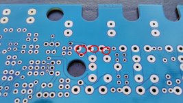
That's strange, I wonder what happened. Looks like there's another one to the lower right of the last red circle that might not pass clearance standards.
My fault: "D S G" materialized as solder side trace instead of silk text ...😱That's strange, I wonder what happened. Looks like there's another one to the lower right of the last red circle that might not pass clearance standards.
- Home
- Amplifiers
- Solid State
- 2stageEF high performance class AB power amp / 200W8R / 400W4R